Ergotron WorkFit-P Manual
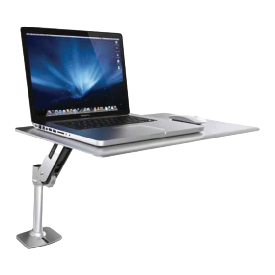
Sit-stand height adjustible workstation
Hide thumbs
Also See for WorkFit-P:
- User manual (8 pages) ,
- Manual (8 pages) ,
- Quick start manual (8 pages)
Advertisement
Quick Links
For the latest User Installation Guide please visit: www.ergotron.com
For the latest User Installation Guide please visit: www.ergotron.com
User's Guide - English
Guía del usuario - Español
Manuel de l'utilisateur - Français
Gebruikersgids - Deutsch
Benutzerhandbuch - Nederlands
Guida per l'utente - Italiano
Användarhandbok - svenska
ユーザーガイ ド : 日本語
用户指南 : 汉语
For local customer care phone numbers visit: http://contact.ergotron.com
888-45-307-G-01 rev. F • 11/13
1 of 9
Advertisement

Related Manuals for Ergotron WorkFit-P


Summary of Contents for Ergotron WorkFit-P
- Page 1 For the latest User Installation Guide please visit: www.ergotron.com For the latest User Installation Guide please visit: www.ergotron.com User's Guide - English Guía del usuario - Español Manuel de l’utilisateur - Français Gebruikersgids - Deutsch Benutzerhandbuch - Nederlands Guida per l’utente - Italiano Användarhandbok - svenska...
- Page 2 Important! You will need to adjust this product after installation is complete. Make sure all your equipment is properly installed on the product before attempting adjustments. This product should move smoothly and easily through the full range of motion and stay where you set it. If movements are too easy or diffi...
-
Page 3: Tools Needed
Components M6 x 14mm 1/4” 2.5 mm 4 mm Tools Needed Optional for Pan Adjustment 13mm 888-45-307-G-01 rev. F • 11/13 3 of 9... -
Page 4: Setup Steps
Set-up Steps Warning: Because mounting surface materials can vary widely, it is imperative that you make sure mounting surface is strong enough to handle mounted product and equipment. CLAMP GROMMET HOLE DESK THICKNESS 0.78"-2.56" (20-65mm) 0.78"-1.38" (20-35mm) 1.18"-2.56" (30-65mm) 0.5"-2.5" (13-64mm) 4 mm CAUTION: Bolt must be... - Page 5 Set-up Steps Warning! Do not move arm until Lock is installed in the next step. Failure to follow these instructions may result in your arm coming off the pole base and causing equipment damage and/or personal injury. The height of the Arms Stop can be moved up or down on pole.
- Page 6 M6 x 14mm NOTE: These screws insert at an angle. 4 mm 888-45-307-G-01 rev. F • 11/13 6 of 9...
- Page 7 Adjustment Step Important! You will need to adjust this product after installation is complete. Make sure all your equipment is properly installed on the product before attempting adjustments. This product should move smoothly and easily through the full range of motion and stay where you set it.
- Page 8 Adjustment Step 13mm Increase Friction If this product moves too easily from side-to-side, then you'll need to increase friction: Decrease Friction If this product is too diffi cult to move from side-to-side, then you'll need to decrease friction: The height of the Arms Stop can be moved up or down on pole. WARNING: Arm must be removed from pole before moving Arm Stop.
-
Page 9: Features And Specifications
Features & Specifi cations 20” 180˚ 360˚ Set Your Workstation to Work For YOU! Learn more about ergonomic computer use at: www.computingcomfort.org Height Position top of screen slightly below eye level. Position keyboard at about elbow height with wrists at. Distance Position screen an arm's length from face—at least 20”...
Need help?
Do you have a question about the WorkFit-P and is the answer not in the manual?
Questions and answers