Table of Contents
Advertisement
Quick Links
INSTRUCTION MANUAL
No.1601
MODEL
- Read and fully understand all the instructions before use.
- Keep this manual in designated place for easy and quick reference.
- The model mentioned on this manual is designed for use outside of Japan.
Warranty shall be void if above mentioned model is used in Japan.
PDX-301N / PDX-302N (N.m)
PDX-501N / PDX-502N (N.m)
PDX-301F / PDX 501F (lbf.ft)
CAUTION
5 0
× 1 0 0
N m
4 0
2 0
3 0
Advertisement
Table of Contents

Related Manuals for Tone Power Digitorqon PDX-302N


Summary of Contents for Tone Power Digitorqon PDX-302N
- Page 1 INSTRUCTION MANUAL No.1601 PDX-301N / PDX-302N (N.m) PDX-501N / PDX-502N (N.m) MODEL PDX-301F / PDX 501F (lbf.ft) 5 0 × 1 0 0 N m 4 0 2 0 3 0 CAUTION - Read and fully understand all the instructions before use. - Keep this manual in designated place for easy and quick reference.
- Page 2 INTRODUCTION Thank you for purchasing ■ Upon receipt, check and confirm the following:: - Check any transport damages. - Check for any loose or lost screws and bolts. - Check the model as per order. - Check all the accessories are contained. (see page 16) If any problems are found, contact your distributor.
- Page 3 SAFETY INSTRUCTIONS This manual specifies three (3) basic safety instructions: ■ Instructions are classified by degree of risk and described as follows: Danger is used to indicate threatening dangerous or unsafe practices which could imminently result in severe personal injury or death in the worst case. Warning is used to indicate hazardous or unsafe practices which could result in severe personal injury or death in the worst occasion.
-
Page 4: Table Of Contents
TABLE OF CONTENTS 1. Application ························································································ 4 2. Precautions for Use ····························································· 4 3. Part Name & Accessories ························································ 15 4. Before Use ······················································································ 18 5. Changing Accessories ································································ 20 6. Operating Procedure ·································································· 29 7. Setting Preset Torque ······························································· 35 8.... -
Page 5: 1. Application
1. Application ■ is an electric torque control wrench with digital torque indicator that shows actual tightening torque being applied on bolts/nuts. Precaution for Use ■ To prevent fire, electric shock, bodily injury and etc, read and follow all instructions listed below. DANGER ●... - Page 6 DANGER ● Do not put hands, fingers or feet close to the reaction plate during operation. ○ The reaction plate rotates in the direction opposite to that of bolt and nut rotation. ○ Never place hands, fingers or feet where reaction plate is placed. Failure to follow this instruction may result in amputation of hands, fingers or feet.
- Page 7 WARNING ● Never use the wrench in a location where flammable substances such as gasoline, gas, thinner, benzene and etc. are stored. ○ The trigger switch emits sparks when it is turned on/off. The commutator motor also emits sparks when it is rotating. Failure to follow this instruction may result in explosion or fire.
- Page 8 WARNING ● Place the reaction plate to a solid member. ○ Select solid member or surface to be placed the reaction plate as those member or surface receives load almost equivalent to that of output torque. Failure to follow this instruction may result in loss of torque precision; damage or deformation of reaction plate or its set screws;...
- Page 9 WARNING ● Avoid overloading. ○ Use the wrench and its accessories within the rated specification. Overloading of the wrench and its accessories may result in damage of the wrench or its accessories; or accident or personal injury. ● Properly install the socket and reaction plate as described in this manual.
- Page 10 WARNING ● Check the following items before operation. ○ Check for any deformation, crack or damage on wrench body, reaction plates, electric cord, power plug, socket, O-ring, pin、 batteries, metal case, hex key wrench and screwdrivers (-). Do not use wrench if any of the above items are abnormal. ○...
- Page 11 CAUTION ● Use commercial power supply to operate the wrench. ● Follow the instructions below when using generator. □ Use 50-60Hz sinusoidal power supply without high harmonic wave. Power supply includes high harmonic wave may cause malfunction or breakage of the wrench. □...
- Page 12 CAUTION ● Keep good motor ventilation. □ Do not put any foreign materials in the vent. □ Do not cover the vent. ● Do not connect multiple plugs to a single outlet by using multiple outlet adaptors. Over current may cause fire, accident or malfunction. ●...
- Page 13 CAUTION ● Reaction force must be taken by area beyond “a” dimension when L-type reaction plate is used. See table below. There is a chance to invite overload when reaction force is taken within “a” dimension which may result in breakage of the HSH set screws, seizure of the output square drive or loss of torque precision.
- Page 14 CAUTION Do not operate wrench in humid condition. ● □ Do not operate wrench in a location subject to rain. □ Refer operating temperature in the specification.(➭P.64) Failure to follow this instruction may result in accident, malfunction or loss of torque precision. ●...
- Page 15 CAUTION ● Secure work area. □ Keep body stance balanced and firmed. □ Never wrap the electric cord around something. □ Keep work area well lit. ● Use suitable model for each application. □ Do not use wrench beyond its rated specification. □...
-
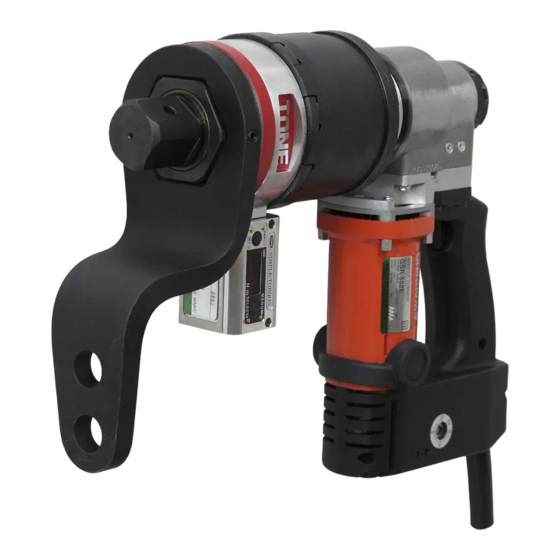
Page 16: 3. Part Name & Accessories
3. Part Name & Accessories Part Name HSH Set Screw Square Drive Reverse Knob L-type Trigger Switch Reaction Plate Motor 5 0 × 1 0 0 N m 4 0 2 0 Display 3 0 Status Light Torque Setting Dial MENU SELECT○... - Page 17 Accessories Straight type Reaction Plate (factory installed) 1 pc L-type Reaction Plate 1 pc HSH Set Screw 4 pcs (2pcs factory installed, 2pcs for replacement) Screwdriver (-) 1 pc Mini Screwdriver (-) 1 pc Hex Key Wrench * 1 pc Metal Case 1 pc CE Connector (only for CE models)
- Page 18 External Dimensions (mm) L L1 5 0 × 1 0 0 N m 4 0 2 0 3 0 ストレート形反力受装着図 b L2 L3 R L 5 0 5 0 × 1 0 0 × 1 0 0 N m N m 4...
-
Page 19: 4. Before Use
4. Before Use ■ Preparation of the wrench and procedures of torque setting are shown in the following. WARNING Check followings before connecting plug into power source. ● Failure to follow these instructions may result in serious injury due to accidental starting. - Page 20 4.6 Set clock (calendar year, month, date and time) of the display before use. NOTE When tightening torque is measured without microSD memory card, the clock is used only for purpose of “5-6 Display setting state and battery power level” (See Page 19.) In this case, setting the clock is not necessary. 4.7 Activate or deactivate an “Auto Start Mode”...
-
Page 21: 5. Changing Accessories
5. Changing Accessories 5.1 Mount or Remove Reaction Plate Mount Reaction Plate Place reaction plate over the reaction base to make parallel installation to the display, then securely tighten by HSH set screws HSH Set Screw x 2pcs Display Reaction Base WARNING ●... - Page 22 Remove Reaction Plate Unscrew HSH set screws to remove reaction plate. NOTE Slightly hit the reaction plate by hammer when it is adhered on the wrench body. Hit the reaction plate by hammer REACTION - 21 -...
- Page 23 5-2. Mount or Remove Impact Socket Mount Impact Socket Prepare adequate impact socket/pin/o-ring suitable for bolt/nut to be tightened. Remove pin from impact socket. Align holes in the square drive and the impact socket. Holes O-Ring Insert pin into the aligned holes and place o-ring in the groove. ...
- Page 24 Remove Impact Socket Remove pin from impact socket then remove impact socket from wrench body. WARNING ● Check for any deformation, crack or damage on the impact socket, pin and o-ring. Damaged socket, pin or o-ring invites serious injury. Since pin and o-ring are expendables, those should be replaced with new ones from time to time.
- Page 25 5-3. Insert or Remove microSD Memory Card Make sure power if OFF. Face battery cover up. Screw Unscrew the screws by screwdriver Cover (+) in a set to remove battery cover. CAUTION Do not allow dust enter into the display. CAUTION Never remove cover tightened by HSH bolts to prevent display from damage caused by static electricity.
- Page 26 Insert microSD Memory Card Fully insert microSD card into the slot as shown in the figure until “click microSD Card sound” is made. Slot Remove microSD Memory Card Push microSD card until “click sound” is made then remove it. CAUTION ●...
- Page 27 5-4. Mount or Remove Optional Lifting Device Mount Lifting Device Remove CRFH screws from housing. Housing CRFH Screws Place spacers on both side of housing and tighten them by CRPH screws. Spacer CRFH Screws Place lifting device on the spacers at either vertical or horizontal position. Lifting Device Vertical Position Horizontal Position...
- Page 28 Then tighten by CRFH screws. Eye Bolt NOTE Lifting device can also be use as sub-handle by removing eye-bolt. Make sure that lifting device is securely installed on the wrench body. - 27 -...
- Page 29 Remove Lifting Device Remove CRFH screws from lifting device. Remove CRPH screws then remove spacers. Put CRFH screws back on the housing. - 28 -...
-
Page 30: 6. Operating Procedure
6. Operating Procedure Run wrench at no-load for about 5 minutes. About 5 minutes of warm up exercise at no-load is necessary for precise torque measurement. CAUTION ● The torque control wrench tend to stop right after the wrench is activated when it is set for minimum torque value and is use in temperature below 10 degrees centigrade. - Page 31 6-2. Turn Display ON Push PWR button for more than 1 second at no-load. Torque measurement is ready when displayed in the window. NOTE Refer page 38 CAUTION ● Do not apply any load until window displays Precise torque measurement cannot be achieved if zero adjustment is improperly made.
- Page 32 CAUTION ● Beware that reaction plate rotates opposite direction to that of bolt/nut rotating direction. ● Reaction force must be taken by area beyond “a” dimension when L-type reaction plate is used. See table below. There is a chance to invite overload when reaction force is taken within “a”...
- Page 33 CAUTION ● Graduation on the torque setting dial is only a rough guidance. □ Tightening torque varies depending on tightening condition. □ It is recommended to adjust torque setting dial each day before operation or whenever tightening condition is changed. ●...
- Page 34 ③ After tightening, there may be some cases that it is hard to take out the wrench from the bolt/nut. In those cases, set the reverse knob to (L) position for counterclockwise direction and then squeeze the trigger switch to release reaction force from the reaction member.
- Page 35 MEMO - 34 -...
-
Page 36: 7. Setting Preset Torque
7. Setting Preset Torque Graduation on the torque setting dial is only a rough guidance. Adjust target torque by following procedure each day before operation or whenever tightening condition is changed (see page 17). - 35 -... - Page 37 CAUTION ● Gradually adjust torque setting dial from low torque to high torque to prevent over loading. ○ Tightening torque varies depending on tightening condition such as condition of bolt/nut, surface condition of steel, length of extension cord, voltage use and etc. ○...
-
Page 38: 8. Using Display
8. Using Display 8-1. Turn Display ON Approx. set up time: 9 sec When microSD card is inserted ① Press PWR button for approx 1 sec at no-load. ② All digits will appeared in the window and power ... - Page 39 When microSD card is not installed Approx. set up time: 6 sec ①Press PWR button for approx 1 sec at no-load. ② All digits will appeared in the window and power is turn on. ③ ( no microSD ) will appear in the ...
- Page 40 8-2. Turn Display OFF ○ Press PWR button for approx 3 sec to turn display off. sign will appear. NOTE Display shuts off automatically when it is not in use for more than 10 minutes (see page 40). ...
- Page 41 8-4 Battery Level ○ Battery level are indicated as follows: (b A t tery falls) (b A t tery almost Low) (b A t tery completely Low) Immediately change batteries when are indicated. (see page 57) CAUTION ●...
- Page 42 8-6. View Setup Condition and Battery Level ○ Setup condition and battery level can be review by pressing SET ● and SELECT ○ buttons at the same time when is indicating. (microSD installed) (No microSD (Auto Start ON)...
- Page 43 CAUTION ● Make sure press SET● button to show each time before next tightening when auto start is OFF . Torque will not be measured if tightening operation is started without displaying ● Never apply load before is displayed. Failure to follow this instruction results in inaccurate torque measurement. ●...
- Page 44 8-7. MENU Function Setup, edit or modify group file, file title, auto start function and clock by pressing MENU button. Show Menu Screen ① Press MENU for approx 1 sec when is displayed in the window to proceed with menu screen. NOTE For list of menu screen, see page 45.
- Page 45 Menu Screens Change group file (see page 46) View measured torque values in a selected group file (see page 47) View title of group file (see page 48) Setup auto start ON/OFF (see page 49) Setup clock (see page 52) NOTE Menu mark with tells that microSD card installation is necessary.
- Page 46 8-7-1. Change Group File (Only when microSD card is installed) Torque data management can be done by group by saving the data in different group files. ① Call “ Change Group ” menu ② Press SET●to run “ Change Group ” menu ...
- Page 47 8-7-2. Display Tightening Torque Data in the Current Group File (Only when microSD card is installed) The tightening torque data in the current “Group file” can be checked sequentially by the button operation. ① On “ Menu screen ” (See Page 26), display and ...
- Page 48 8-7-3. Display Name of Group File (Only when microSD card is installed) The name of file in the microSD memory card to which the current group file is stored can be identified through the button operation. ①On “ Menu screen ” (See Page 26), display and ...
- Page 49 8-7-4. Turn ON/OFF Auto Start Mode In the auto start mode, tightening torque measurement starts automatically as the variation in tightening torque is detected. Advantage and Disadvantage of Auto Start Mode Press SET ● button Pressing Button Not necessary before measurement Upon turning on the power, Upon turning...
- Page 50 CAUTION is not displayed upon the power on, the auto start mode is OFF. SET● must be pressed to start measurement. ● CAUTION When the tightening torque is measured with auto start mode ON, the battery life can be shorter than that with auto start mode OFF due to increasing power consumption.
- Page 51 ○Tightening procedure when auto start mode is OFF ① When is not displayed, press SET● button to display for approx 0.5 NOTE The window reads second while “Zero adjustment” is automatically performed (See Page) CAUTION Before starting “Zero point adjustment” by pressing SET ●...
- Page 52 8-7-5. Set Clock ① On “ Menu screen ” (See Page 26), display and scroll the 5th menu. ② Press to run the displayed menu. SET● ③ “ Clock setting screen ” appears and blinks calendar year.
- Page 53 MEMO - 52 -...
-
Page 54: 9. Microsd Memory Card Storage Format
9. microSD memory card storage format “ DIGITORQON ” saves measurements of tightening torque to Date Folder on the microSD memory card in the data folder format Group File as shown in the figure below. Composition of Data Folder microSD memory 0710001 0710001... - Page 55 Storage Format of Group File SERIAL No.,0710001 DATA No.,TORQUE[Nm],TIME[hh:mm:ss],DATE[YYYY/MM/DD],OVERLOAD,OPERATION,Remark_1 1,800,16:21:00,2007/12/01,PowerON, 2,801,16:22:31,2007/12/01,ZeroAdjustment, 3,799,16:23:20,2007/12/01,,AutoStart, 4,800,16:24:15,2007/12/01,,AutoStart, DATA No. TORQUE[Nm] TIME[hh:mm:ss] 5,799,16:25:31,2007/12/01,,AutoStart, Open Group File with 16:21:00 ・・・・・・・・・・・・・・・・・・・ spreadsheet ... 16:22:31 998,1001,23:58:59,2007/12/01,ErrorOverLoad,AutoStart, 16:23:20 16:24:15 999,800,23:59:59,2007/12/01,ZeroAdjustment, 16:25:31 (ファイルの最後) ・・・・・・・・・・・・・・・・・・・ 1001 23:58:59 23:59:59 The serial number of “DIGITORQON” is placed at the top of the group file. ...
- Page 56 CAUTION ● If microSD memory card is not in the microSD slot upon turning on the power to “POWER DIGITORQON”, tightening torque data will not be stored on the microSD memory card (See Page 11) □Check for display of upon turning on the power (See Page 14). ●...
-
Page 57: 10. Changing Batteries
10. Changing Batteries ①Make sure that power is OFF (➭P.) ②Rotate the display control section until the torque display window faces down. ③Using the stubby screwdriver, unscrew 2 screws (+ head) from the back side of the torque display window and then remove the cover. Screws Cover ... - Page 58 Battery Case Battery Pay attention to the wiring while taking out the battery case. CAUTION ⑤Install new 4 batteries. Use size AA alkaline dry cells or nickel hydride rechargeable CAUTION batteries. ⑥Replace the battery case into the display control section. Make sure that the wiring is not bitten.
- Page 59 WARNING ● Use size AA alkaline dry cells or nickel hydride rechargeable batteries. Failure to heed this warning will cause fire, burn wound, injury, accident, malfunction, liquid leakage or accuracy issue. ● Handle batteries with care. ○ Install the batteries with correct polarity by referring to the markings on the battery case.
-
Page 60: 11. Error And Status Indication
11. Error and Status indication 11-1. LED for judgment and error indication DIGITORQON is provided with green and red LED that indicate whether the tightening has successfully completed or not, or an error has occurred or not. : Lights Out : Light On : Quick On &... - Page 61 11-2. Error and Status Indication of Torque Readout Device [Error Over Load] Load is applied beyond maximum torque of “ DIGITORQON(➭P.42) [Error Revers Rotation] Counter clockwise rotation is detected. [Error microSD] Incompletely installation or lack of storage can happen for the microSD memory card.
-
Page 62: 12. Maintenance
12. Inspection & Maintenance WARNING ● Disconnect plug from power source before inspection and maintenance. Accidental starting invites serious injury. ①Use only a damp cloth to clean your POWER DIGITORQON and impact sockets since certain cleaning agents and solvents are harmful to those parts. -
Page 63: 13. Periodic Inspection
13. Regular Inspection ● Carry out overhaul once a year or 5,000 tightening, whichever comes first. Contact your distributor for details of overhaul. ● The minimum storage period for spare parts of the products mentioned on this instruction manual is 7 years after discontinuing these products. - 62 -... -
Page 64: 14. Features
14. Features ○ Double insulated electric wrench. ○ Measures and indicates tightening torque. ○ Tightening torque data management can be done to insert the microSD memory card into digital torque indicator. ○ Reading tightening torque data and measurement time stored in CSV text format on microSD memory card on a PC. -
Page 65: 15. Specifications
15. Specifications Model -301N -302N -501N -502N -301F -501F Voltage (Single Phase) 115V 230V 115V 230V 115V 115V Max Current (A) Max Power(W) 1350W 2s/3s 1350W 750~ 1,500~ Controllable Torque 1,000 2,000 2,200 3,700 Range (N・m) ~3,000Nm ~5,000N.m lbf・ft lbf・ft Repeated Accuracy (%) +/-5% ※... -
Page 66: 16. After-Sales Service
16. Aftersales Service ● Use “POWER DIGITORQON” properly according to this instruction manual and WARNING LABEL on the body of “POWER DIGITORQON”. ● Provide model, serial number, date of purchase and details of failure when contacting your distributor. CAUTION ● Do not use “POWER DIGITORQON” when malfunction, deficiency in its performance, personal injury or property loss is foreseen. - Page 67 EC DECLARATION OF CONFORMITY We hereby declare that the following our product conform to the essential health and safety requirements of EC Directives. Directives Machinery Directive, 2006/42/EC EMC Directive, 2004/108/EC RoHS Directive, 2011/65/EU The above product has been evaluated for conformity with above directives using the following European standards.
- Page 68 IMKA016...
Need help?
Do you have a question about the Power Digitorqon PDX-302N and is the answer not in the manual?
Questions and answers