
Related Manuals for Burkert 8228


Summary of Contents for Burkert 8228
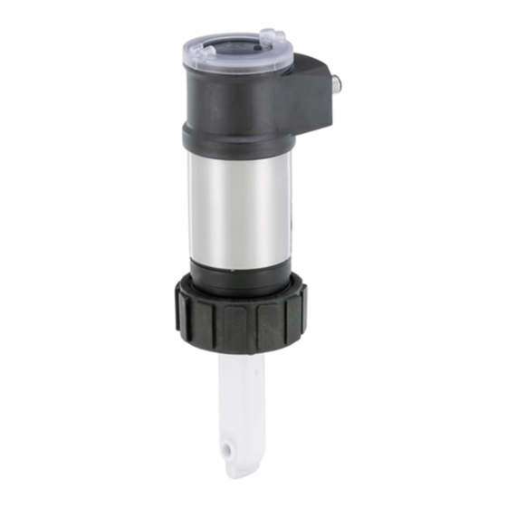
- Page 1 Type 8228 Inductive conductivity meter Induktives Leitfähigkeits-Messgerät Conductimètre inductif Quickstart English Deutsch Français...
- Page 2 We reserve the right to make technical changes without notice. Technische Änderungen vorbehalten. Sous réserve de modifications techniques. © Bürkert SAS, 2014 - 2018 Quickstart 1809/04_EU-ML 00567368 / ORIGINAL_FR...
-
Page 3: Table Of Contents
1.1 Definition of the word "device" ............4 8.1 Safety instructions .................15 1.2 Validity of this quickstart ..............4 8.2 Installing a 8228 with a G2'' process connection in the pipe .....................16 1.3 Symbols used..................4 8.3 Installing a 8228 with a 2'' clamp process connection 2 intended use . -
Page 4: About The Quickstart
Validity of this quickstart This quickstart describes the entire life cycle of the device. Please This quickstart is valid for the Type 8228 ELEMENT conductivity meter version V2. keep this quickstart in a safe place, accessible to all users and any new owners. -
Page 5: Intended Use
Advice or important recommendations. The Type 8228 ELEMENT conductivity meter is intended solely for the measurement of the conductivity. ▶ Use the device in compliance with the characteristics and Refers to information contained in this quickstart or in other commissioning and use conditions specified in the contractual documents. -
Page 6: Basic Safety Information
Type 8228 Basicsafetyinformation bAsic sAfeTy informATion This safety information does not take into account any contingencies risk of injury due to the nature of the fluid. or occurrences that may arise during installation, use and mainte- ▶ Respect the prevailing regulations on accident prevention and nance of the device. -
Page 7: General Information
EN 61340-5-1 norm. information on the internet ▶ Also make sure that you do not touch any of the live electrical You can find the Operating Instructions and technical data sheets components. for Type 8228 at: www.burkert.com English... -
Page 8: Understanding The Rating Plate
1. Supply voltage plATe 2. Type of the device 3. Measurable variable 4. Version 8228 Inductive Conductivity Meter 5. Max. power consumption Supply: 12-36V 40W max. 6. Max. current available at the transistor output(s) Output: 1x 4-20mA 1xTrans 700mA max. -
Page 9: Technical Data
Type 8228 Technicaldata TechnicAl DATA 6.2.1 conformity to the pressure equipment Directive conditions of use → Make sure the device materials are compatible with the fluid. Ambient temperature –10...+60 °C → Make sure the pipe DN and PN are adapted for the device. -
Page 10: Fluid Data
Type 8228 Technicaldata 6.2.2 ul certification • 8228 with conductivity • 0...+80 °C sensor in PP The devices with variable key PU01 or PU02 are UL certified devices and comply also with the following standards: • 8228 with conductivity • –15...+130 °C sensor in PEEK •... -
Page 11: Mechanical Data
Type 8228 Technicaldata part material P (bar) Fixed connector holder stainless steel 316L PEEK Screws stainless steel PVDF Conductivity sensor holder / seal • PVDF / FKM (in contact with the fluid) • PP / FKM • PEEK / FKM... -
Page 12: Dimensions Of Device
Type 8228 Technicaldata Dimensions of device G2'' process connection → please refer to the technical data sheets related to the device avalaible at: www.burkert.com Nickel-plated brass Silicone (or stainless steel) electrical data Stainless steel power supply 12...36 v dc • Connection to main supply: per- EPDM... -
Page 13: Data Of The Connectors And Wires
Type 8228 Technicaldata Data of the connectors and wires transistor output polarized • type • NPN (/sink) or PNP(/source) number of fixed type of connector (through wiring and through connectors parameterizing) 1 male M12 fixed 5-pin M12 female connector (not • NPN output • 1...36 V DC, 700 mA max. (or connector supplied). -
Page 14: Assembly
Type 8228 Assembly Assembly mounting the display module → Remove the cover. safety instructions 20° → Set the display module Warning at an angle of about 20° in relation to the desired risk of injury due to non-conforming assembly. position. ▶ The device must only be assembled by qualified and skilled staff with the appropriate tools. -
Page 15: Installation And Wiring
Type 8228 Installationandwiring insTAllATion AnD WirinG Warning safety instructions risk of injury due to non-conforming installation. ▶ The electrical and fluid installation can only be carried out by Danger qualified and skilled staff with the appropriate tools. risk of injury due to electrical voltage. ▶ Install appropriate safety devices (correctly rated fuse and/or ▶... -
Page 16: Installing A 8228 With A G2'' Process Connection In The Pipe
Type 8228 Installationandwiring → installing a 8228 with a G2'' process Calibrate the zero point of conductivity (see chap. 9.7). → connection in the pipe Install the device in the fitting as shown in Fig. 7: The device is put into a fitting Type S020 mounted on the pipe. -
Page 17: Installing A 8228 With A 2'' Clamp Process Connection In The Pipe
Type 8228 Installationandwiring → installing a 8228 with a 2'' clamp Install the device in the fitting as shown in Fig. 8. process connection in the pipe → Select a seal (mark 4) that is com- Danger patible with the 2'' clamp connection risk of injury if the stainless steel adapter of the device is of the device and with the fluid. -
Page 18: Wiring The Device
Type 8228 Installationandwiring Wiring the device 8.4.1 Assembling the male or female fixed connector (available as an accessory) Danger → Unscrew the nut [1] on the risk of injury due to electrical voltage. body [4]. → ▶ Shut down the electrical power source of all the conductors and Insert the cable into the isolate it before carrying out work on the system. - Page 19 Type 8228 Installationandwiring 8.4.2 making the installation equipotential To ensure the equipotentiality of the installation (power supply - device - medium): → Connect together the various earth spots in the installation to eliminate the potential differences that may occur between dif- ferent earthes.
- Page 20 Type 8228 Installationandwiring 8.4.3 Wiring a version with a single m12 fixed connector Load Transistor output (TR1) white V+ (12...36 V DC) blue brown Current output (AC1) grey Fig. 12: Pin assignment of the male fixed connector on a version with a black single M12 fixed connector pin of the m12 female cable available as colour of the wire an accessory (article number 438680) brown white blue black 12-36 V DC grey 4...20 mA input at exter-...
- Page 21 Type 8228 Installationandwiring 8.4.4 Wiring a version with 2 m12 fixed connectors Load male fixed connector Transistor output 1 (TR1) white V+ (12...36 V DC) brown blue Current output 1 (AC1) grey female fixed connector black Transistor output 2 (TR2) V+ (12...36 V DC)
- Page 22 Type 8228 Installationandwiring Connect the power supply for the device to the male fixed Load 1 Load 2 connector; the supply is then transferred internally to pins 1 and 3 of the female fixed connector in order to ease wiring of the load to the female fixed connector.
-
Page 23: Operating And Commissioning
Type 8228 Operatingandcommissioning operATinG AnD commissioninG Load 1 Load 2 • The settings can only be done on a device with a display module. • Do not remove the display module while making the set- white tings on the device. -
Page 24: Using The Navigation Button
Type 8228 Operatingandcommissioning using the navigation button Warning danger due to non-conforming commissioning. Non-conforming commissioning could lead to injuries and damage Symbolised by Symbolised by in this this quickstart the device and its surroundings. quickstart ▶ Before commissioning the device, calibrate the conductivity sensor (see chap. 9.7). - Page 25 Type 8228 Operatingandcommissioning you want to... press... you want to... press..browse in the Process ...browse in the dynamic • next function: level functions bar (MEAS, • next screen: BACK, ABORT, OK, YES, • previous function: • previous screen: ...confirm the highlighted • ...access the Settings...
-
Page 26: Using The Dynamic Functions
Type 8228 Operatingandcommissioning using the dynamic functions you want to... choose..go back to the Process level, without dynamic function "MEAS" Yellow LED: shows that Green LED: shows that the device is energized transistor 1 is switched confirming the modifications made ...validate the input dynamic function "OK"... -
Page 27: Knowing The Operating Levels
Type 8228 Operatingandcommissioning knowing the operating levels icon meaning and alternatives The device has 2 operating levels: the Process level and the Con- Sensor in good condition, fluid conductivity and fluid figuration level. temperature within the set ranges. • When the device is powered up or the display module mounted... -
Page 28: Calibrating The Zero Point Of Conductivity
Type 8228 Operatingandcommissioning calibrating the zero point of entering the correction factor of the conductivity fitting used → From the Process level, access the Configuration level. The correction factor depends on the shape, the material and the → diameter of the fitting used. The following table gives the correction Access the menu "Calib". - Page 29 Type 8228 Operatingandcommissioning Table 1: Correction factors of the fittings S020, depending on the shape, the material and the DN of the fittings fittings with true union connec- fittings with internal or external measurement tions or fittings with weld ends thread connections or fittings with chamber welding sockets or fusion spigots weld end connections pvdf brass stainless steel stainless steel pvdf <32 1.08 1.08 1.08 0.99 0.99 1.08 1.08 1.08 0.99 0.99 0.99 1.04 1.04 1.04 0.99 0.99 0.99 1.02 1.02 1.02 0.99 0.99...
-
Page 30: Maintenance And Troubleshooting
Type 8228 Maintenanceandtroubleshooting mAinTenAnce AnD TroubleshooTinG risk of injury due to the nature of the fluid. 10.1 safety instructions ▶ Respect the prevailing regulations on accident prevention and safety relating to the use of dangerous fluids. Warning risk of injury due to electrical voltage. ▶ Shut down the electrical power for all the conductors and iso- risk of injury due to non-conforming maintenance. -
Page 31: Storage
Type 8228 Storage sTorAGe notiCe poor storage can damage the device. ▶ Store the device in a dry place away from dust. ▶ Storage temperature of the device: –10...+60 °C. DisposAl of The DeVice → Dispose of the device and its packaging in an environmentally- friendly way. - Page 32 www.burkert.com...