
Related Manuals for Bürkert 8228 ELEMENT


Summary of Contents for Bürkert 8228 ELEMENT
-
Page 1: Operating Instructions
Type 8228 ELEMENT Inductive conductivity meter Induktives Leitfähigkeits-Messgerät Conductimètre inductif Operating Instructions Bedienungsanleitung Manuel d‘utilisation... - Page 2 We reserve the right to make technical changes without notice. Technische Änderungen vorbehalten. Sous réserve de modifications techniques. © Bürkert SAS, 2014 - 2016 Operating Instructions 1603/2_EU-ML 00565588 / Original FR...
-
Page 3: Table Of Contents
Type 8228 Contents About this mAnuAl ..................................6 Definition of the word "device" ............................6 1.1 Validity of the manual ................................6 1.2 symbols used ..................................6 1.3 intenDeD use ....................................7 bAsic sAfety informAtion ..............................8 GenerAl informAtion ................................10 manufacturer's address and international contacts ..................10 4.1 Warranty conditions ................................10 4.2 information on the internet ............................10 4.3 Description ....................................11 5.1 Area of application ................................11 5.2 Knowing the device ................................11 5.3 Knowing the available versions ..........................12 5.4 understanding the name plate ............................13 technicAl DAtA . - Page 4 Type 8228 instAllAtion AnD WirinG ..............................22 8.1 safety instructions ................................22 8.2 installing a 8228 with a G2'' process connection in the pipe ..............23 8.3 installing a 8228 with a 2'' clamp process connection in the pipe................24 8.4 Wiring the device .................................25 8.4.1 Assembling the male or female connector (see chap. "11 Accessories and spare parts") 26 8.4.2 Making the installation equipotential ....................26 8.4.3 Wiring a version with a single M12 fixed connector ..............27 8.4.4 Wiring a version with 2 M12 fixed connectors ................30 operAtinG AnD commissioninG .
- Page 5 Type 8228 9.11.9 Setting the parameters of the current outputs ................49 9.11.10 Setting the parameters of the transistor outputs ................50 9.11.11 Choosing the type of temperature compensation ..............52 9.12 Knowing the calibration menu ............................53 9.12.1 Activating/deactivating the Hold function ..................53 9.12.2 Modifying the Calibration menu access code ................53 9.12.3 Adjusting the current outputs ......................54 9.12.4...
-
Page 6: About This Manual
Type 8228 Aboutthismanual AbouT This mAnuAl This manual describes the entire life cycle of the device. Please keep this manual in a safe place, accessible to all users and any new owners. this manual contains important safety information. Failure to comply with these instructions can lead to hazardous situations. Pay attention in particular to the chapters "Basic safety information"... -
Page 7: Intended Use
Type 8228 Aboutthismanual ▶ Indicates an instruction to be carried out to avoid a danger, a warning or a possible risk. → Indicates a procedure to be carried out. Indicates the result of a specific instruction. inTenDeD use use of the device that does not comply with the instructions could present risks to people, nearby installations and the environment. The 8228 conductivity meter is intended solely for the measurement of the conductivity. ▶... -
Page 8: Basic Safety Information
Type 8228 Basicsafetyinformation bAsic sAfeTy informATion This safety information does not take into account: • any contingencies or occurences that may arise during installation, use and maintenance of the devices. • the local safety regulations for which the operating company is responsible including the staff in charge of installation and maintenance. - Page 9 Type 8228 Basicsafetyinformation Various dangerous situations To avoid injury take care: ▶ not to use the device for the measurement of the conductivity of gases. ▶ not to use the device in explosive atmospheres. ▶ not to use the device in an environment incompatible with the materials it is made of. ▶...
-
Page 10: General Information
Type 8228 Generalinformation GenerAl informATion 4.1 manufacturer's address and international contacts To contact the manufacturer of the device, use following address: Bürkert SAS Rue du Giessen BP 21 F-67220 TRIEMBACH-AU-VAL You may also contact your local Bürkert sales office. The addresses of our international sales offices are available on the internet at: www.burkert.com 4.2 Warranty conditions... -
Page 11: Description
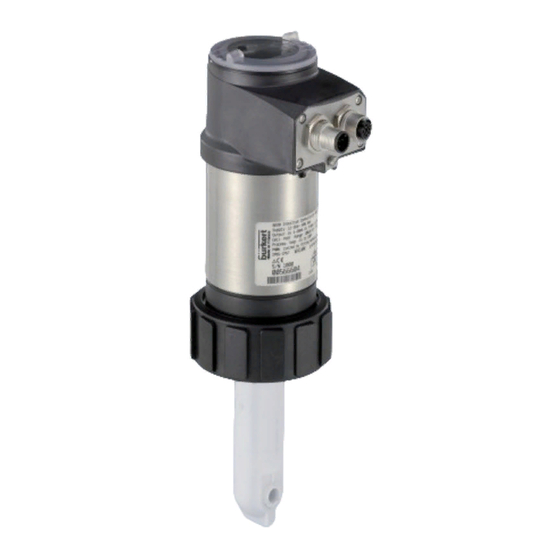
Type 8228 Description DescripTion 5.1 Area of application The device is intended to measure the conductivity. Thanks to one or two fully adjustable transistor outputs, the device can be used to switch a solenoid valve, activate an alarm and, thanks to one or two 4-20-mA current outputs, establish one or two control loops. -
Page 12: Knowing The Available Versions
Type 8228 Description 5.3 Knowing the available versions The following versions of the device are available. Each version is available without or with the display module. All versions of the device require a power supply of 12-36 V DC. materials order code process electrical outputs without connection connection... -
Page 13: Understanding The Name Plate
Type 8228 Description 5.4 understanding the name plate 8228 Inductive Conductivity Meter Supply: 12-36V 40W max. Output: 1x 4-20mA 1xTrans 700mA max. Cell: PEEK Range 100 µS/cm - 2 S/cm Process: Temp -15 to 130°C PN 10, limited by fitting material and fluid temp. 2:NPN/PNP1 IP65-IP67 W41MN... -
Page 14: Technical Data
Type 8228 Technicaldata TechnicAl DATA 6.1 operating conditions Ambient temperature -10 to +60 °C Air humidity < 85 %, non condensated Height above sea level max. 2000 m Installation category acc. to UL 61010-1 Category I Degree of pollution acc. to EN 61010-1 Degree 2 Protection class acc. -
Page 15: Fluid Data
Type 8228 Technicaldata 6.3 fluid data Fluid temperature The fluid temperature may be restricted by the fluid pressure, the material the conductivity sensor holder is made of and the material the S020 fitting used is made of (see Fig. 2). • 8228 with conductivity sensor in PVDF •... -
Page 16: Mechanical Data
Type 8228 Technicaldata 6.4 mechanical data part material Box / seals stainless steel 316L 1.4404, PPS / EPDM Cover / seal PC / silicone Display module PC / PBT M12 fixed connector • nickel-plated brass (stainless steel on request) • stainless steel for 2'' clamp process connection Fixed connector holder stainless steel 316L Screws... -
Page 17: Electrical Data
Type 8228 Technicaldata 6.6 electrical data Power supply 12-36 V DC • filtered and regulated • SELV circuit, with a safe energy level • oscillation rate: ±10 % Power source (not supplied) • limited power source according to paragraph 9.3 of EN 61010-1 standard •... -
Page 18: Data Of The Connectors And Wires
Type 8228 Technicaldata 6.7 Data of the connectors and wires number of fixed connectors type of connector 1 male M12 fixed connector 5-pin M12 female connector (not supplied). For the female M12 connector with order code 917116, use a shielded cable: • diameter: 3 to 6.5 mm • wire cross section: max. 0.75 mm 1 male M12 fixed connector and 1 female M12 5-pin M12 female connector (not supplied) and 5-pin M12 male fixed connector... -
Page 19: Assembly
Type 8228 Assembly Assembly 7.1 safety instructions Danger risk of injury due to electrical voltage. ▶ Shut down and isolate the electrical power source before carrying out work on the system. ▶ Observe all applicable accident protection and safety regulations for electrical equipment. Warning risk of injury due to non-conforming assembly. ▶ The device must only be assembled by qualified and skilled staff with the appropriate tools. risk of injury due to unintentional switch on of power supply or uncontrolled restarting of the installation. -
Page 20: Mounting The Cover
Type 8228 Assembly 7.3 mounting the cover → Check that there is a seal on the housing and that it is not damaged. Replace it if necessary. → Grease the seal if necessary, using a component compatible with the seal material. → [1] Set the cover to ensure that the 4 grooves of the cover match with the 4 pins of the housing. -
Page 21: Dismounting The Display Module
Type 8228 Assembly 7.5 Dismounting the display module → Remove the cover (see chap. 7.2). → Turn the module by ca. 20° counterclockwise. Once unlocked, the module is raised slightly by the spring 20° action. → Remove the module from its housing. Fig. 7: Dismounting the display module English... -
Page 22: Installation And Wiring
Type 8228 Installationandwiring insTAllATion AnD WirinG 8.1 safety instructions risk of injury due to electrical voltage. ▶ If a 12-36 V DC powered version is installed either in a wet environment or outdoors, all the electrical voltages must be of max. 35 V DC. ▶ Disconnect the electrical power for all the conductors and isolate it before carrying out work on the system. ▶... -
Page 23: Installing A 8228 With A G2'' Process Connection In The Pipe
Type 8228 Installationandwiring Protect this device against electromagnetic interference, ultraviolet rays and, when installed outdoors, the effects of the climatic conditions. 8.2 installing a 8228 with a G2'' process connection in the pipe The device is put into a fitting S020 mounted on the pipe. → Mount the fitting on the pipe obeying the instructions of the operating instructions of the fitting used. Fig. 8: ... -
Page 24: Installing A 8228 With A 2'' Clamp Process Connection In The Pipe
Type 8228 Installationandwiring → Install the device in the fitting as shown in Fig. 10: → Make sure the seal (mark 2) is on the conductivity sensor. → Make sure the material of the seal is compatible with the fluid to be measured. -
Page 25: Wiring The Device
Type 8228 Installationandwiring → Install the device in the fitting as shown in Fig. → Select a seal (mark 4) that is compatible with the 2'' clamp con- nection of the device and with the fluid. → Put the seal (mark 4) on the fitting (mark 5). →... -
Page 26: Assembling The Male Or Female Connector (See Chap. "11 Accessories And Spare Parts")
Type 8228 Installationandwiring 8.4.1 Assembling the male or female connector (see chap. "11 Accessories and spare parts") → Unscrew the nut [1] on the body [4]. → Insert the cable into the nut [1], the cable clamp [2] and the seal [3], and then into the body [4]. → Strip 20 mm of the cable. →... -
Page 27: Wiring A Version With A Single M12 Fixed Connector
Type 8228 Installationandwiring 12-36 V DC Power supply Plastic pipe Devices such as valves, pumps,... Fig. 14: Equipotentiality skeleton diagram with pipes in plastic 8.4.3 Wiring a version with a single m12 fixed connector Transistor output (TR1) V+ (12-36 V DC) Current output (AC1) Fig. 15: Pin assignment of the male fixed connector on a version with a single M12 fixed connector pin of the m12 female cable available as an accessory (order code 438680) colour of the wire brown white blue black grey Load white brown blue grey Power supply... - Page 28 Type 8228 Installationandwiring Load white brown blue grey Power supply 12-36 V DC Fig. 17: PNP wiring of the transistor output of a version with 1 fixed connector (parameter setting "PNP/source") 4-20 mA input at external instrument brown black grey blue Power supply 12-36 V DC Fig. 18: Wiring in sinking mode of the current output of a version with 1 fixed connector (parameter setting "NPN/sink") 4-20 mA input at external instrument brown black grey blue Power supply 12-36 V DC...
- Page 29 Type 8228 Installationandwiring Load white blue brown grey black 4-20 mA input at external Power supply instrument 12-36 V DC Fig. 20: NPN wiring of the transistor output and and wiring in sinking mode of the current output of a version with 1 fixed connector (parameter setting "NPN/sink") Load white brown blue grey black 4-20 mA input at external Power supply instrument 12-36 V DC Fig. 21: PNP wiring of the transistor output and and wiring in sourcing mode of the current output of a version with 1 fixed ...
-
Page 30: Wiring A Version With 2 M12 Fixed Connectors
Type 8228 Installationandwiring 8.4.4 Wiring a version with 2 m12 fixed connectors Transistor output 1 (TR1) Transistor output 2 (TR2) V+ (12-36 V DC) V+ (12-36 V DC) Current output 2 (AC2) Current output 1 (AC1) female fixed connector male fixed connector Fig. 22: Pin assignment of the male and female M12 fixed connectors connect the power supply for the device to the male fixed connector; the supply is then transferred internally to pins 1 and 3 of the female fixed connector in order to ease wiring of the load to the female fixed connector. pin of the female or male m12 cables available as accessories colour of the wire (order code 438680 respectively 559177) brown white blue black grey... - Page 31 Type 8228 Installationandwiring 4-20 mA input at exter- 4-20 mA input at external nal instrument instrument brown brown grey black black blue Power supply 12-36 V DC Fig. 25: Wiring of both current outputs in sinking mode, on a version with 2 fixed connectors (parameter setting "NPN/ sink") 4-20 mA input at 4-20 mA input at external instrument external instrument black brown blue...
- Page 32 Type 8228 Installationandwiring Load 1 Load 2 white white blue brown blue black black grey 4-20 mA input at 4-20 mA input at external instrument external instrument 12-36 V DC Power supply Fig. 28: PNP wiring of both transistor outputs and wiring of both current outputs in sourcing mode, on a version with 2 fixed connectors (parameter setting "PNP/source") English...
-
Page 33: Operating And Commissioning
Type 8228 Operatingandcommissioning operATinG AnD commissioninG • The settings can only be done on a device with a display module. • Do not remove the display module while making the settings on the device. 9.1 safety instructions Warning risk of injury due to non-conforming operating. Non-conforming operating could lead to injuries and damage the device and its surroundings. ▶... -
Page 34: Using The Navigation Button
Type 8228 Operatingandcommissioning configuration level This level comprises 5 menus: Menu title Relevant icon "Param": see chap. 9.11 This is when the device is be- ing parame- tered........ "Calib": see chap. 9.12 "Diagnostic": see chap. 9.13 "Test": see chap. 9.14 "Info": see chap. 9.15 9.3 using the navigation button Symbolised by... - Page 35 Type 8228 Operatingandcommissioning you want to... press... • ...access the Settings level • ...display the Param menu for at least 2 sec., from any screen of the Process level ...browse in the menus of the Settings level • next menu: • previous menu: ...access the menu displayed ...browse in the menu functions •...
-
Page 36: Using The Dynamic Functions
Type 8228 Operatingandcommissioning 9.4 using the dynamic functions you want to... choose..go back to the Process level, without confirming the modifi- dynamic function "MEAS" cations made ...validate the input dynamic function "OK" ...go back to the parent menu dynamic function "BACK" ... abort the current operation and go back to the parent menu dynamic function "ABORT"... -
Page 37: Browsing In A Menu (Example)
Type 8228 Operatingandcommissioning 9.6 browsing in a menu (example) Title of the current menu, sub-menu or The icon identifies the current function. menu Param The arrow indicates that some more This is when the device is be- functions are available which can be ing parame- tered.... -
Page 38: Knowing The Display At The Power-Up Of The Device
Type 8228 Operatingandcommissioning icon meaning and alternatives Sensor in good condition, fluid conductivity and fluid temperature within the set ranges. If the monitoring of the conductivity and/or the fluid temperature and/or the fluid conductivity has been activated, the alternative icons in this position are: •... -
Page 39: Knowing The Process Level
Type 8228 Operatingandcommissioning 9.8 Knowing the process level CondS First view of the 1.423 ms/cm Process level. tempc 55 °c Display of the cur- 18.3 mA rent outputs. 7.5 mA conds Zoom on the value 1.423 in the first line. Zoom on the value of the first 18.3 mA current output. -
Page 40: Accessing The Configuration Level
Type 8228 Operatingandcommissioning 9.9 Accessing the configuration level > 2s Param This is when the This is This is when the Any view of the when the device is be- device is be- device is be- ing parame- ing parame- tered.... tered.... ing parame- .... -
Page 41: Knowing The Structure Of The Menus Of The Configuration Level
Type 8228 Operatingandcommissioning 9.10 Knowing the structure of the menus of the configuration level See chap. 9.9 to access the Configuration level. If an "upload" has been succesfully made with Param System Up/Download Download Downl. Yes/No this module Upload Yes/No Upload This is This is when the when the device is be- device is be- ing parame-... - Page 42 Type 8228 Operatingandcommissioning Param Outputs HWMode sink/NPN source/PNP This is This is when the when the device is be- device is be- ing parame- ing parame- tered.... tered............ PVar: CondS AC1/AC2 CondR TempC TempF TDSppm INPUT 4mA: 20mA: INPUT Filter: None Fast...
- Page 43 Type 8228 Operatingandcommissioning Calibrate Zero Calib Sensor Probe Zero Calib. Point? Processing RESULT Calibration INPUT Cell constant INPUT K-fitting INPUT Cell cst. TDS INPUT Calib interval Last cal. date READ Interval INPUT Teach special Start temp INPUT Stop temp INPUT Processing Temperature INPUT Diagnostic...
- Page 44 Type 8228 Operatingandcommissioning Test System Code 0*** Confirm code 0*** Outputs AC1: INPUT AC2: INPUT TR1: OFF/ON TR2: OFF/ON Sensor PVar: CondS CondR TempC TempF TDSppm Value: INPUT Info Error MESSAGE Warning MESSAGE Mainten. MESSAGE Smiley MESSAGE Software Main READ READ Sensor Product READ...
-
Page 45: Knowing The Parameters Menu
Type 8228 Operatingandcommissioning 9.11 Knowing the parameters menu 9.11.1 Transferring data from one device to another See chap. 9.9 to access the Parameters menu. This function is only possible with a display module with software version V2. → On the device, check the software version in the menu "Info -> Software -> Main". •... -
Page 46: Modifying The Param Menu Access Code
Type 8228 Operatingandcommissioning 9.11.3 modifying the pArAm menu access code See chap. 9.9 to access the Parameters menu. Param System Code 0*** Confirm code 0*** Enter the new Enter the new code a This is This is when the when the device is be- device is be- code second time ing parame-... -
Page 47: Setting The Data Displayed In The Process Level
Type 8228 Operatingandcommissioning 9.11.5 setting the data displayed in the process level See chap. 9.9 to access the Parameters menu. Param Display Line1 / Line2: Enabled Disabled This is This is when the when the device is be- device is be- ing parame- PVar: CondS ing parame- tered.... tered.... -
Page 48: Displaying Of The Lowest And Highest Values Measured
Type 8228 Operatingandcommissioning 9.11.6 Displaying of the lowest and highest values measured See chap. 9.9 to access the Parameters menu. Param Display Min/Max: Status: Enabled Disabled This is This is when the when the device is be- device is be- PVar: CondS ing parame- ing parame- tered.... tered........ -
Page 49: Choosing The Output Wiring Mode
Type 8228 Operatingandcommissioning 9.11.8 choosing the output wiring mode See chap. 9.9 to access the Parameters menu. HWMode source/PNP Param Outputs sink/NPN This is when the This is device is be- when the ing parame- device is be- tered.... ing parame- ....tered........ The wiring mode is the same for all outputs. →... -
Page 50: Setting The Parameters Of The Transistor Outputs
Type 8228 Operatingandcommissioning Functions “4mA” and “20mA” are used to define the measurement range for the process value associated with the current on the 4-20 mA output. and P are the values associated with a current of 4 mA or 20 mA respectively: If P is higher than P , the signal is inverted and the range P... - Page 51 Type 8228 Operatingandcommissioning PVAR: choose a measurable variable (impedance in W.cm, conductivity in S/cm, temperature in °C, temperature in °F or total dissolved solids in ppm) associated with transistor output 1 resp. transistor output 2 or associate the “warning” message (see chap. 9.12.4, chap. 9.13.2 and chap. 9.13.3) with transistor output 1 resp. transistor output 2.
-
Page 52: Choosing The Type Of Temperature Compensation
Type 8228 Operatingandcommissioning 9.11.11 choosing the type of temperature compensation See chap. 9.9 to access the Parameters menu. This menu is used to deactivate the temperature compensation (choice “none”) or choose the type of temperature compensation to determine the conductivity of the fluid: • according to a linear percentage (choice “linear”, see "Linear temperature compensation (choice “Linear”)", page 52). -
Page 53: Knowing The Calibration Menu
Type 8228 Operatingandcommissioning 9.12 Knowing the calibration menu 9.12.1 Activating/deactivating the hold function See chap. 9.9 to access the Calibration menu. Calib System Hold Hold:Disable Hold:Enable If the mode "Hold" is activated and if there is a power interruption, then, when the device restarts, the mode "Hold" is automatically deactivated. The mode "Hold"... -
Page 54: Adjusting The Current Outputs
Type 8228 Operatingandcommissioning 9.12.3 Adjusting the current outputs See chap. 9.9 to access the Calibration menu. Calib Outputs AC1 / AC2 4mA: INPUT 20mA: INPUT 4mA: adjust the current output 1 or current output 2 for 4 mA. When the "4mA" function is selected, the device generates a current of 4 mA: measure the current emitted by the 4-20 mA output using a multimeter and enter the value given by the multimeter in the function “AC1.4mA”... - Page 55 Type 8228 Operatingandcommissioning The accuracy of the conductivity measurements is influenced by: • the drift of the zero point of conductivity. Correct the drift of the zero point with the function ZERO CALIB. To be done if the conductivity of the air measured by the conductivity sensor is higher than 10 µS/cm (see "Cali- brate the zero point of conductivity (function "Zero Calib."...
- Page 56 Type 8228 Operatingandcommissioning calibrate the zero point of conductivity (function "Zero calib." of the menu "probe") • In order not to interrupt the process, activate the HOLD function (see chap. 9.12.1). • Before each calibration, fully clean the conductivity sensor with a special cleaning agent, then rince and dry. If the value of air conductivity measured is higher than 10 µS/cm, readjust the device, holding the sensor in the air (zero point of conductivity of the device).
- Page 57 Type 8228 Operatingandcommissioning calibrate the conductivity sensor (“calibration” function in the “probe” menu) Calibration consists in determining the C constant specific to each conductivity sensor using a solution with a known conductivity. • In order not to interrupt the process, activate the HOLD function (see chap. 9.12.1). • Before each calibration, fully clean the conductivity sensor with a special cleaning agent. •...
- Page 58 Type 8228 Operatingandcommissioning Calib Sensor Probe Calibration → Immerse the clean conductivity sensor in the solution with a known conductivity. The device alternately displays: • the measured conductivity of the solution • the measured temperature of the solution → Enter the conductivity, at Calibration the fluid temperature, of 5.023 µS/cm...
- Page 59 Type 8228 Operatingandcommissioning Define the temperature compensation curve specific to your process (“teach special” function in the”probe” menu) Calib Sensor Probe Teach special Start temp +40.00°C → Enter the value for the start of the temperature range for which the com- pensation curve must be determined. Stop temp +55.00°C The fluid temperature range (T-; T+) must be entered in such a way that the difference between T- and T+ is greater than 8 °C.
-
Page 60: Entering An Offset For The Temperature Measurement
Type 8228 Operatingandcommissioning 9.12.5 entering an offset for the temperature measurement See chap. 9.9 to access the Calibration menu. The temperature transmitted by the temperature probe may be corrected. This correction value is the temperature offset. Calib Sensor Temperature INPUT Enter the temperature offset (±5 °C) 9.13 Knowing the Diagnostic menu 9.13.1 modifying the Diagnostic menu access code See chap. -
Page 61: Monitoring The Fluid Temperature
Type 8228 Operatingandcommissioning When the device generates a "warning" or an "error" event: → go into the “Info” menu to read the cause of the event generation. → and/or go into the “Sensor” function of the Diagnostic menu to read the measured conductivity value. →... -
Page 62: Knowing The Test Menu
Type 8228 Operatingandcommissioning When the device generates a "warning" or an "error" event: → go into the “Info” menu to read the cause of the event generation. → and/or go into the “Sensor” function of the Diagnostic menu to read the measured temperature value. →... -
Page 63: Checking The Outputs Behaviour
Type 8228 Operatingandcommissioning AC1: check that current output 1 is working correctly by entering a current value and then selecting “OK”. AC2: check that current output 2 is working correctly by entering a current value and then selecting “OK”. TR1: check that transistor output 1 is working correctly by selecting the status of the transistor (“ON” or “OFF”) then “OK”. -
Page 64: Knowing The Information Menu
Type 8228 Operatingandcommissioning 9.15 Knowing the information menu 9.15.1 reading the cause of events linked to icons See chap. 9.9 to access the Information menu. Info Error MESSAGE Warning MESSAGE Mainten. MESSAGE Smiley MESSAGE Software Main READ READ Sensor Product READ The function allows for reading a short description of the reason why the following icons are displayed by the device: - ERROR: - WARNING:... -
Page 65: Maintenance And Troubleshooting
Type 8228 Maintenanceandtroubleshooting mAinTenAnce AnD TroubleshooTinG 10.1 safety instructions risk of injury due to electrical voltage. ▶ Shut down the electrical power source of all the conductors and isolate it before carrying out work on the system. ▶ All equipment connected to the 8619 shall be double insulated with respect to the mains according to the standard IEC 61010-1:2010. -
Page 66: Solving A Problem
Type 8228 Maintenanceandtroubleshooting 10.3 solving a problem red current transistor icon message dis- possible cause recommended action output output played in the info menu → 22 mA depending on "Sensor not The connection to the Switch the device off thresholds found" measurement module is and on again. interrupted. → If the problem per- sists, return the device to Bürkert. - Page 67 Type 8228 Maintenanceandtroubleshooting red current transistor icon message dis- possible cause recommended action output output played in the info menu → 22 mA depending on "TR EE Fact Parameter reading error. Switch the device off thresholds Read" and on again. → If the error persists, set the device back to the default settings (chap.
- Page 68 Type 8228 Maintenanceandtroubleshooting red current transistor icon message dis- possible cause recommended action output output played in the info menu → 22 mA depending on "E:Conductivity" The fluid conductivity is Go into the "Sensor" thresholds out of range. function of the Diagnostic menu to The message is read the measured displayed if the fluid temperature...
- Page 69 Type 8228 Maintenanceandtroubleshooting red current transistor icon message dis- possible cause recommended action output output played in the info menu → 4-20 mA Switched + "W:Conductivity" The fluid conductivity is Go into the "Sensor" out of range. function of the Diagnostic menu to The message is read the measured displayed if the fluid temperature monitoring of the fluid...
-
Page 70: Accessories And Spare Parts
Type 8228 Accessoriesandspareparts Accessories AnD spAre pArTs CaUTiOn risk of injury and/or damage caused by the use of unsuitable parts. Incorrect accessories may cause injuries and damage the device and the surrounding area. ▶ Use only original accessories and original replacement parts from Bürkert. Accessory order code Display module 559 168 Set with 2 opaque covers, with seals: 560 948 - 1 screw cover with 1 EPDM seal - 1 quarter turn closing cover with 1 silicone seal... -
Page 71: Storage
Type 8228 Storage sTorAGe nOTe poor storage can damage the device. ▶ Store the device in a dry place away from dust. ▶ Storage temperature of the device: -10 to +60 °C. DisposAl of The proDucT → Dispose of the device and its packaging in an environmentally-friendly way. nOTe Damage to the environment caused by parts contaminated by the fluid. - Page 72 Type 8228 English...
- Page 74 www.burkert.com...
Need help?
Do you have a question about the 8228 ELEMENT and is the answer not in the manual?
Questions and answers