Table of Contents
Advertisement
Quick Links
www.proform.com
Model No. PFEL5105.0
Serial No.
Serial
Number
Decal
QUESTIONS?
If you have questions, or if parts are
damaged or missing, DO NOT
CONTACT THE STORE; please
contact Customer Care.
IMPORTANT: Please register this
product (see the limited warranty
on the back cover of this manual)
before contacting Customer Care.
1-888-533-1333
CALL TOLL-FREE:
Mon.–Fri., 6 a.m.–6 p.m. MT
Sat. 8 a.m.–4 p.m. MT
ON THE WEB:
www.proformservice.com
CAUTION
Read all precautions and instruc-
tions in this manual before using
this equipment. Keep this manual
for future reference.
USERʼS MANUAL
Advertisement
Table of Contents

Related Manuals for Pro-Form 850


Summary of Contents for Pro-Form 850
- Page 1 www.proform.com USERʼS MANUAL Model No. PFEL5105.0 Serial No. Serial Number Decal QUESTIONS? If you have questions, or if parts are damaged or missing, DO NOT CONTACT THE STORE; please contact Customer Care. IMPORTANT: Please register this product (see the limited warranty on the back cover of this manual) before contacting Customer Care.
-
Page 2: Table Of Contents
TABLE OF CONTENTS WARNING DECAL PLACEMENT ............. .2 IMPORTANT PRECAUTIONS . -
Page 3: Important Precautions
IMPORTANT PRECAUTIONS WARNING: To reduce the risk of serious injury, read all important precautions and instructions in this manual and all warnings on your elliptical before using your elliptical. ICON assumes no responsibility for personal injury or property damage sustained by or through the use of this product. -
Page 4: Before You Begin
Thank you for selecting the revolutionary PROFORM manual. To help us assist you, note the product model ® 850 elliptical. The 850 elliptical exerciser provides an number and serial number before contacting us. The impressive selection of features designed to make model number and the location of the serial number your workouts at home more effective and enjoyable. -
Page 5: Assembly
ASSEMBLY To hire an authorized service technician to assemble the elliptical, call 1-800-445-2480. Assembly requires two persons. Place all parts of the elliptical exerciser in a cleared area and remove the packing materials. Do not dispose of the packing materials until assembly is completed. In addition to the included tool(s), assembly requires a Phillips screwdriver , an adjustable wrench... - Page 6 To make assembly easier, read the information on page 5 before you begin. While another person lifts the Base (1), attach the Front Stabilizer (6) to the Base with two M10 x 80mm Carriage Bolts (82) and two M10 Locknuts (81). 2.
- Page 7 3. Attach the Rear Stabilizer (7) to the Frame (2) with two M10 x 127mm Button Screws (83). Next, hold the handle on the Frame (2), press the Latch Button (68), and lower the Frame until the Rear Stabilizer (7) is resting on the floor. Handle 4.
- Page 8 5. While another person holds the Upright (3), connect the Upper Wire Harness (48) to the Lower Wire Harness (49). Gently pull the upper end of the Upper Wire Avoid pinching Harness (48) to remove any slack, and insert the wires the Upright (3) into the Base (1).
- Page 9 7. The Console (5) can use four D batteries (not included); alkaline batteries are recommended. IMPORTANT: If the Console has been exposed to cold temperatures, allow it to warm to room temperature before inserting batteries. Otherwise, you may damage the console displays or other electronic compo- Tabs nents.
- Page 10 9. Identify the Left Handlebar (8) and the Left Upper Body Leg (11), which are marked with “Left” stickers, and orient them as shown. Insert the Left Handlebar (8) into the Left Upper Body Leg (11). Attach the Left Handlebar (8) with two M8 x 43mm Button Bolts (78) and two M8 Jam Nuts (79).
- Page 11 11. Hold the Left Front and Left Rear Handlebar Covers (18, 19) around the Left Upper Body Leg (11). Attach the Left Front and Left Rear Handlebar Covers (18, 19) with three M4 x 32mm Round Head Screws (105). Attach the Right Front and Right Rear Handlebar Covers (20, 21) in the same way.
- Page 12 13. Apply a coat of grease to one of the Pedal Arm Axles (32) and to the two Pedal Arm Bushings (33) in the Left Pedal Arm (14). Next, slide an M8 Washer (88) and a Pedal Arm Cover (31) onto an M8 x 23mm Shoulder Screw (115), and turn the Shoulder Screw a few turns into the Pedal Arm Axle (32).
-
Page 13: How To Use The Elliptical
HOW TO USE THE ELLIPTICAL HOW TO FOLD AND UNFOLD THE ELLIPTICAL HOW TO MOVE THE ELLIPTICAL When the elliptical is not in use, the frame can be To move the elliptical, first fold it as described at the folded out of the way. First, lift the latch under each left. - Page 14 HOW TO EXERCISE ON THE ELLIPTICAL To mount the elliptical, hold the handlebars and step onto the pedal that is in the lowest position. Next, step onto the other pedal. Push the pedals until they begin Handlebars to move with a continuous motion. Note: The crank arms can turn in either direction.
- Page 15 FEATURES OF THE CONSOLE Each pulse control program automatically controls the resistance of the pedals and prompts you to increase The advanced console offers an array of features or decrease your pedaling pace to keep your heart designed to make your workouts more effective and rate near a target heart rate setting during your work- enjoyable.
- Page 16 HOW TO USE THE MANUAL MODE 4. Monitor your progress with the display. 1. Press the Resistance decrease button or begin The left side of the pedaling to turn on the console. display—The left side of the display will show A moment after the console is turned on, the dis- the elapsed time and play will light.
- Page 17 5. Measure your heart rate if desired. 6. Turn on the fan if desired. If there are sheets of To turn on the fan at low speed, press the Fan but- plastic on the metal Metal Contacts ton. To turn on the fan at high speed, press the contacts on the hand- button a second time.
- Page 18 HOW TO USE A PULSE CONTROL PROGRAM If pulse control program 2 is selected, the tar- get heart rate setting for the program will flash in 1. Press the Resistance decrease button or begin the display. If desired, press the Resistance pedaling to turn on the console.
- Page 19 During both pulse control programs, the con- Note: During the program, you can manually over- sole will regularly compare your heart rate to the ride the resistance setting, if desired, by pressing target heart rate setting. If your heart rate is too far the increase and decrease buttons.
- Page 20 HOW TO USE A RESISTANCE & RPM PROGRAM As you exercise, the Pace Coach will help you to keep your pedaling pace near the pace setting for 1. Press the Resistance decrease button or begin the current segment. When one of the “Too Slow” pedaling to turn on the console.
- Page 21 4. Monitor your progress with the display. The program will continue until the resistance set- ting for the last segment is shown in the Current Segment column and the last segment ends. See step 4 on page 16. 5. Measure your heart rate if desired. Note: During the program, you can override the resistance setting for the current segment, if desired, by pressing the increase or decrease but-...
-
Page 22: Maintenance And Troubleshooting
MAINTENANCE AND TROUBLESHOOTING HANDGRIP PULSE SENSOR TROUBLESHOOTING Inspect and tighten all parts of the elliptical regularly. Replace any worn parts immediately. • Avoid moving your hands while using the handgrip To clean the elliptical, use a damp cloth and a small pulse sensor. -
Page 23: Exercise Guidelines
EXERCISE GUIDELINES WARNING: Burning Fat—To burn fat effectively, you must exer- cise at a low intensity level for a sustained period of Before beginning this time. During the first few minutes of exercise, your or any exercise program, consult your physi- body uses carbohydrate calories for energy. -
Page 24: Part List
PART LIST—Model No. PFEL5105.0 R0410A Key No. Qty. Description Key No. Qty. Description Base Drive Belt Frame Flywheel Upright C-magnet Console Bracket Pillow Block Console Magnet Front Stabilizer Spring Rear Stabilizer Idler Left Handlebar Idler Bracket Right Handlebar Clamp Handlebar Cap Reed Switch Bracket Left Upper Body Leg Base Pin... - Page 25 Key No. Qty. Description Key No. Qty. Description M4 x 16mm Round Head Screw Wave Washer Motor Washer Star Washer M4 x 16mm Screw M10 Washer M4 x 14mm Screw M6 Nut M4 x 32mm Round Head Screw M8 x 23mm Shoulder Screw M8 x 31mm Shoulder Screw Flywheel Bracket M4 x 12mm Screw...
-
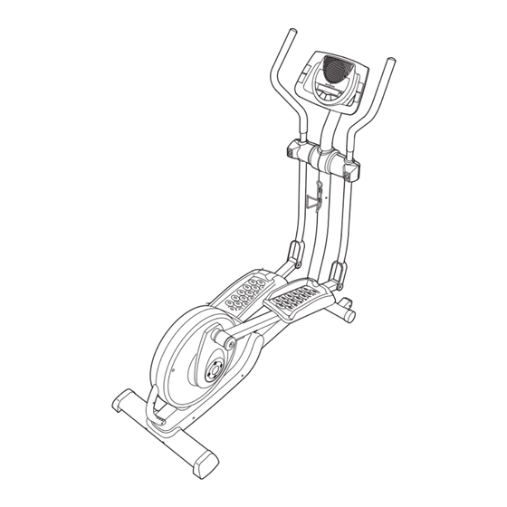
Page 26: Exploded Drawing
EXPLODED DRAWING A—Model No. PFEL5105.0 R0410A... - Page 27 EXPLODED DRAWING B—Model No. PFEL5105.0 R0410A...
-
Page 28: Ordering Replacement Parts
ORDERING REPLACEMENT PARTS To order replacement parts, see the front cover of this manual. To help us assist you, please be prepared to provide the following information when contacting us: • the model number and serial number of the product (see the front cover of this manual) •...
Need help?
Do you have a question about the 850 and is the answer not in the manual?
Questions and answers