
Related Manuals for KUHN MOUNTED MINOTOR 3050


Summary of Contents for KUHN MOUNTED MINOTOR 3050
- Page 1 OPERATOR’S MANUAL SILAGE LOADER / STRAW BLOWER / DISTRIBUTOR MOUNTED MINOTOR 3050 SEMI-MOUNTED MINOTOR 3050 BELT-DRIVEN MINOTOR 3060 PLEASE READ CAREFULLY BEFORE USING THE MACHINE AN067A GB 02-2008...
- Page 2 IMPORTANT INFORMATION The KUHN machine that you have just purchased has undergone a full range of inspections throughout the manufacturing process. If you should encounter a fault in spite of all the care given to the manufac- ture of your machine, please contact your dealer who will solve the problem with the assistance of our after-sales service.
-
Page 3: Table Of Contents
DESCRIPTION OF THE MOUNTED MINOTOR 3050 __________________ DESCRIPTION OF THE SEMI-MOUNTED MINOTOR 3050 AND THE BELT-DRIVEN MINOTOR 3060 _____________________________ TECHNICAL SPECIFICATIONS ______________________________________ DESCRIPTION OF THE CONTROLS _________________________________ Mounted/Semi-Mounted MINOTOR 3050 Remote Control Cables ____________ Minotor 3060 Remote Control Cables __________________________________ STARTING UP ___________________________________________________ Hitching... -
Page 4: Message To The User
KEEP THIS MANUAL AVAILABLE FOR REFERENCE. Your KUHN dealer will instruct you on the general operation of your machine. He wants you to get the best performance possible and will be glad to answer any special questions that may arise regarding the operation of the KUHN machine. -
Page 5: Safety Instructions
SAFETY The symbol above is used throughout this manual each time recommendations are made concerning your safety, the safety of others, or the good operation of the machine. These recommendations must be made known to all machine operators. DESIGNATED USE OF THE MACHINE MINOTOR 3050 and MINOTOR 3060 silage loader/distributor/straw blower machines must only be used for the jobs for which they have been designed. - Page 6 GENERAL POINTS 1. In addition to the instructions contained in this manual, comply with safety and accident prevention legislation. 2. Warnings affixed to the machine provide indications on safety measures to be applied and help to avoid accidents. 3. When driving on public roads, follow the Highway Code in your country. 4.
- Page 7 20. Beware! Before operating the loading device (arm and grab), unfolding the cover or raising the body, make sure that there can be no accidental contact with a power line. 21. Beware! Never stand by the delivery chute while the machine is in operation. 22.
- Page 8 HITCHING 1. On hitching or unhitching the machine from the tractor, put the hydraulic lift control lever in such a position that the lift cannot be activated accidentally. 2. Beware! There is a risk of crushing and shearing in the three-point lifting zone. 3.
- Page 9 15. When the universal drive shaft has been disconnected from the tractor PTO, refit the protective cap. 16. Any damaged PTO and universal drive shaft guards must be replaced immediately. 17. Beware! Only use the machine with a PTO speed of 540 rpm. 18.
- Page 10 9. Spare parts must comply with the standards and specifications laid down by the manufacturer. Only use Kuhn original spare parts. 10. Before carrying out any electrical welding work on the tractor or towed machine, disconnect the cables from the alternator and battery.
- Page 11 NOTES...
-
Page 12: Safety Labels
LABELS RELATING TO SAFETY Adhesive labels have been placed on your machine as represented below. Their object is to contribute to your safety and to that of others as well as to the correct operation of the machine. Read their contents and check their location. - Page 13 BEFORE COMMISSIONING THE MACHINE, READ THE INSTRUCTION MANUAL AND THE RULES OF SAFETY CHECK CHAIN TENSION REGULARLY BEFORE CARRYING OUT ANY MAINTENANCE ON THE MACHINE, SWITCH OFF THE TRACTOR ENGINE, REMOVE THE KEY FROM THE IGNITION AND WAIT UNTIL ALL MOVING PARTS HAVE STOPPED COMPULSORY.
-
Page 14: Lighting Equipment
LIGHTING EQUIPMENT MINOTOR 3050 - MINOTOR 3060 Lighting equipment is fitted as standard on the machines in accordance with current legislation. The equipment includes: - 1 LH tail light (A) - 1 RH tail light (B) - 2 reflective triangles (C) - Page 15 NOTES...
-
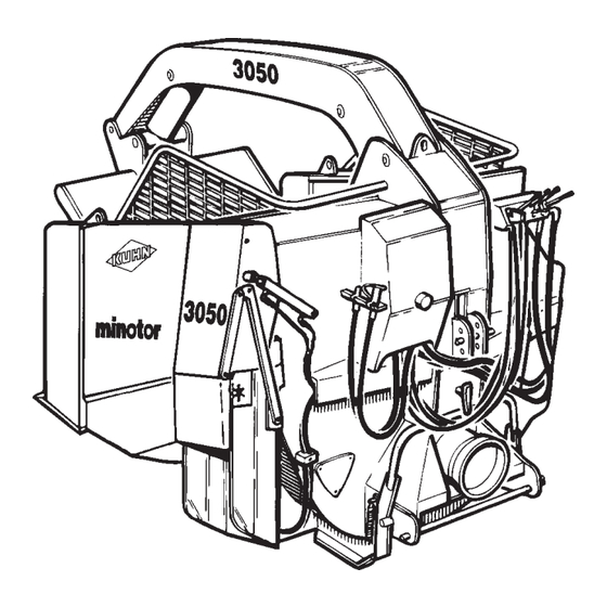
Page 16: Description Of The Mounted Minotor 3050
DESCRIPTION OF MOUNTED MINOTOR 3050... - Page 17 ATHENOR 756011111 1- BODY 2- DELIVERY CHUTE 3- CONTROL UNIT 4- DRIVE UNIT 5- TURBINE 6- PROTECTIVE BOWL 7- ARM 8- GRAB 9- ARM RAM 10- GRAB RAM 11- CONVEYOR SPEED INDICATOR 12- THREE-POINT LINKAGE...
-
Page 18: Description Of The Semi-Mounted Minotor 3050
DESCRIPTION OF SEMI-MOUNTED MINOTOR 3050 AND BELT-DRIVEN MINOTOR 3060... - Page 19 1 - BODY 2 - WHEEL 3 - AXLE 4 - DELIVERY CHUTE 5 - PARKING STAND 6 - TOW BAR 7 - CONTROL UNIT 8 - DRIVE UNIT 9 - DRIVE SHAFT SUPPORT 10 - TURBINE 11 - TAIL LIGHTS 12 - PROTECTIVE BOWL 13 - CONVEYOR REDUCTION GEAR 14 - ARM...
-
Page 20: Technical Specifications
TECHNICAL SPECIFICATIONS MOUNTED MINOTOR 3050 Mounted silage loader / straw-blower / distributor with hydraulic axle. Hydraulic drive on the loading device and distribution / spreading system. REF. DEFINITION MOUNTED MINOTOR 3050 Overall width, chute closed 1,94 Overall width, chute opened... - Page 22 Tractor output max. l/min * Depending on tractor (take account of lifting height) The optional mixing hopper and hydraulic unit are factory-fitted on the semi-mounted MINOTOR 3050 only. Options - Free wheel homokinetic transmission - Heavy-duty wheels: 7.50x15 16 PR - Anti-clogging kit for rectangular bales - Narrow wheels: 7.50x16 10 PR...
-
Page 24: Description Of The Controls
DESCRIPTION OF THE CONTROLS REMOTE CONTROL CABLES MOUNTED / SEMI-MOUNTED MINOTOR 3050 RAISING / LOWERING THE MACHINE BODY (SEMI-MOUNTED 3050) Lever A The movements are made by pressing the switch on the control handle. Push lever up to lower the body. - Page 25 RAISING/LOWERING THE ARM Lever B Push the lever up to raise the arm. Pull the lever down to lower the arm. OPENING/CLOSING THE GRAB Lever B Turn lever to the left to open the grab out of the body. Turn lever to the right to bring the grab in towards the body. CHANGING THE TURBINE SPEED Lever C Push the lever for a turbine speed of 270 min...
- Page 26 ADJUSTING THE DELIVERY CHUTE SPEED The speed of chute movement is adjusted by a flow limiter (1) on the ram. To adjust, unlock the limiter (Allen key n° 2) then select the speed by turning the knobs. Tighten the knob to reduce the speed of chute movement.
-
Page 27: Minotor 3060 Remote Control Cables
BELT-DRIVEN MINOTOR 3060 ENGAGING AND DISENGAGING THE BEATER BAR Lever A Pull lever down to engage the beater bar. Push lever up to disengage the beater bar. RAISING / LOWERING THE MACHINE BODY Lever A The movements are made by pressing the switch on the control handle. Turn lever to the left to lower the body. - Page 28 RAISING / LOWERING THE ARM Lever B Push the lever up to raise the arm. Pull the lever down to lower the arm. OPENING / CLOSING THE GRAB Lever B Turn lever B to the left to open the grab out of the body. Turn lever B to the right to bring the grab in towards the body.
- Page 29 ADJUSTING THE DELIVERY CHUTE SPEED The speed of chute movement is adjusted by a flow limiter (1) on the ram. To adjust, unlock the limiter (Allen key n° 2) then select the speed by turning the knobs. Tighten the knob to reduce the speed of chute movement.
-
Page 30: Starting Up
STARTING UP HITCHING Before hitching the machine, make sure that there is sufficient ballast on the front axle of the tractor. Ballast should be added to the special supports according to the tractor manufacturer’s instructions. The front axle load must be not be less than 20% of the unladen tractor weight. - Page 31 Mounted Machine The Minotor can be attached to all tractors with a standardised three-point lift. It is equipped as standard with a category 2 linkage, complete with a 28 mm dia. trunnion drawbar, 825 mm long between the ball joints. - Position the drawbar on the lifting arms.
- Page 32 - When the tractor engine has been coupled up, adjust the upper link length so that the machine is resting firmly on the ground (photo 3). - Insert the upper link pin (photo 3) and fit the locking pin. - Once the machine is hitched to the tractor, stabilise the three-point linkage laterally with the special device (bars, chains, shims, etc.) (photo 4).
-
Page 33: Adjusting The Position Of The Controls
ADJUSTING THE POSITION OF THE CONTROLS Remote control cables There are two types of control unit mounting: . Mounting the unit on the machine. This is designed for mounting the control unit when the machine is uncoupled from the tractor. . -
Page 34: Transmission
TRANSMISSION Working Parts (PTO and universal drive shafts) Carefully read the instructions supplied with the transmission. 1. Only use universal drive shafts supplied with the machine or recommended by the manufacturer. 2. The PTO and universal drive shaft guards must always be fitted and in good condition. 3. -
Page 35: Connections
UNIVERSAL DRIVE - At maximum extension, there must be a tube overlap of A = 330 mm (Fig. 4). Fig. 4 Fig. 5 - At maximum overlap (with the drive shaft compressed), there must be a safety gap of B = 20 mm to prevent the tubes striking the jaws (Fig. - Page 36 The hydraulic connection to the tractor may be made in one of three ways: 1. Single-acting distributor pressure and direct return to tank. 2. Double-acting distributor pressure and return to second orifice of the same distributor (beware of direction of oil flow) 3.
-
Page 37: Preliminary Checks
ADJUSTING THE DELIVERY CHUTE - The MINOTOR delivery chute can now be set to two positions: 1. A wide opening for the distribution of fibrous products (long hay, round bales of haylage, etc.) (photo 1). 2. A narrow opening for the distribution of fine-cut products and straw blowing (photo 2). -
Page 38: No-Load Tests
NO-LOAD TESTS Do not stand in the working area of the machine. Before starting up, the user must familiarise himself with the machine’s operating controls and their respective functions. Once work has begun, it will be too late. Before starting up the machine, check around the machine (beware of children!). -
Page 39: Operation
MACHINE OPERATION Read carefully before starting up the machine. The machine must be used by one person only. Before starting up the machine and beginning work, check around the machine (beware of children!). Make sure that you have sufficient visibility. Keep people away from the danger area of the machine. -
Page 40: Loading Bales
Loading (Fig. 2 showing an ALTOR 7560) 1. Lower the machine. It should rest on its ground plate at the front and on its shoe at the rear. 2. Start up the hydraulic circuit on the tractor and bring up to nominal speed. 3. -
Page 41: Transport
2 mins.). 4. DISTRIBUTION MOUNTED AND SEMI-MOUNTED MINOTOR 3050 / MINOTOR 3060 Before getting down from the tractor or before any operations on the machine, lay the machine on the ground, switch off the engine, remove the key from the ignition and wait until all moving parts are at a standstill. - Page 42 Silage distribution - The turbine should be set to 270 min - Engage the tractor PTO. - Start up the tractor hydraulics and bring up to nominal speed. - Position the chute so that the silage is correctly channelled towards the floor or a manger. - Release the grab slightly to ensure that the product is not packed too tightly.
- Page 43 Straw bedding - The fan should be set to 540 min - Engage the tractor PTO. - Start up the tractor hydraulics and bring up to nominal speed. - Position the chute so that the straw is projected where required. - For even spreading, the bale must remain in permanent contact with the beater bar without over- jamming it with the claw.
- Page 44 Note: Should the turbine or beater bar become jammed, use the hook mounted inside the housing on the left-hand side of the machine (see photo below) to pull out the jammed product at the distribution chute or beater bar, then use a lever to ensure that the turbine can rotate freely.
-
Page 45: Distribution From A Belt-Driven Minotor 3060
BELT-DRIVEN MINOTOR 3060 Always start the PTO before engaging the belt drive and always disengage the belt drive before stopping the PTO. Failure to comply with this procedure will result in a blockage. Always start the beater bar with the conveyor speed set to zero. Always check that the fan is set to 270 min for silage and haylage and 540 for straw. -
Page 46: Using A Belt-Driven Beater Bar
ADJUSTING THE LIMIT OF TRAVEL SENSOR CLUTCH CONNECTING ROD A5250636 POSITION SWITCH ADJUSTMENT STOP - In the engaged position: 2 mm clearance between stop and switch in “full in” position. M4X40 HEX SOCKET HD SCREW M4 NUT POSITION SWITCH A7040714 USING A BELT-DRIVEN BEATER BAR 1. -
Page 47: Options
OPTIONS The optional equipment listed in the table below is available for the machines. OPTIONS 3050 P 3050 TR 3050 TR / T M 3060 Belt Free wheel wide angle PTO shaft Narrow wheels 7.50 x 16 10 PR Heavy-duty wheels 7.50 x 15 16 PR Auxiliary hydraulic unit Anti-clogging kit for rectangular bales Mixing hopper... -
Page 48: Free Wheel Wide Angle Pto Shat
FREE WHEEL HOMOKINETIC TRANSMISSION PTO shaft assembly providing a greater angle of deflection and free rotation of the turbine. Please read the manual supplied with the transmission carefully. MIXING HOPPER ELECTRONIC PROPORTIONING DEVICE Mineral distributor which may be equipped with a proportioning unit. Please read the manuals supplied with the hopper and proportioning device carefully. -
Page 49: Tyres
TYRES Before carrying out any operations on the tyres, make sure that the trailer is perfectly stable and cannot move accidentally (fit chocks). Wheels and tyres should only be fitted, removed and repaired by persons with the necessary knowledge and the appropriate statutory tools to do the job. Check tyre pressure regularly. -
Page 50: Anti-Clogging Kit For Rectangular Bales
ANTI-CLOGGING KIT FOR RECTANGULAR BALES Device regulating the input of straw into the turbine. DESCRIPTION - Three anti-clogging regulators - Six M10 washers - Six HM 10 x 20 screws FITTING - The three regulators (A) are mounted inside the machine body, just above the beater bar. Riveted nuts are already in place to take the M10 screws. -
Page 51: Hydraulic Unit
HYDRAULIC UNIT Hydraulic unit designed to provide sufficient hydraulic power to ensure correct machine operation. DESCRIPTION - Auxiliary hydraulic unit. - Driven by tractor PTO. - 38 cm³ pump - 37 litre tank with filter and level gauge - Circuit protected by valve calibrated to 180 bar. - Recommended oil: Shell HYDRAU PW (ISO 46 type). - Page 52 MAINTENANCE - Comply with the safety instructions relating to machine maintenance. - Periodically check the oil level in the tank (level gauge - ref. 9). The oil level should not be below the top 1/3 of the gauge. - Change the hydraulic oil after the first 500 hours of work. We recommend an ISO 46-grade hydraulic oil (e.g.
-
Page 54: Maintenance
Spare parts must comply with the standards and specifications laid down by the manufacturer. Only use Kuhn spare parts. Before carrying out any electrical welding work on the tractor or towed machine, disconnect the cables from the alternator and battery. -
Page 55: Conveyor Chain Tension
CONVEYOR CHAIN TENSION To be checked every 100 hours. If the sag exceeds 150 mm, tighten up the chains. To tighten the chains: - Open the door (1) with the two levers (2) (Photo 1). - Loosen the check nuts (3) with a 30 mm wrench (Photo 2). - Tighten the assembly with the nuts (4) using a 30 mm wrench. -
Page 56: Maintenance Schedule
MAINTENANCE SCHEDULE Beware! The schedule indicated below has been calculated for normal conditions of use. If the working conditions prove more difficult, grease more often. Every After Every Every After Every Every 2000 After 1500 hours 1 hour hours hours hours hours hours hours or every year Tighten wheel bolts (100 N.m ) Tighten drawbar eyebolts... -
Page 57: Oil Change
OIL CHANGE The oil needs to be changed in: - the conveyor reduction gear unit, quantity 0.5 litres (Figure 1) - the gearbox, quantity 5 litres (Figure 2). Change the oil after the first 50 hours of work, then every 1500 hours thereafter. Check the oil level regularly to prevent abnormal damage to the units. -
Page 58: Troubleshooting Guide
TROUBLESHOOTING GUIDE P R O B L E M S P O S S I B L E C A U S E S W H A T T O D O L o a d i n g d i ffi c u l ti e s In s u ffic ie n t g ra b p o w e r H y d ra u lic p ro b le m . - Page 59 PROBLEMS POSSIBLE CAUSES WHAT TO DO Turbine rattling when PTO engaged Clutch slipping . Gradually engage the PTO to a suitable intermittently speed. If your machine is equipped with with a free wheel transmission and your tractor with a hydraulic PTO clutch, refer to your dealer (problem with progressive clutch rate irrespective of tractor engine speed).
- Page 60 NOTES...
-
Page 61: Warranty
Kuhn-Audureau warranty but by the respective manufacturer’s warranty. - Claims relating to such parts will be handled in the same way as if they were Kuhn-Audureau parts. However compensation will depend on the warranty agreement of the manufacturer concerned, insofar as the latter acknowledges the validity of the claim. - Page 62 - Return of the warranty certificate duly signed by the dealer and user on commissioning. - Claims shall only be made on a Kuhn-Audureau claim form and sent by the dealer to the Company within a period of one month of the date of the incident.
- Page 63 THIS EQUIPMENT COMPLIES WITH THE LABOUR CODE The manufacturer declines all responsibility should use of the equipment not comply with the recommendations contained in this manual. The user shall observe health and safety rules and Agricultural Insurance Fund recommendations. Our safety rules and advice are not restrictive.
- Page 64 All apparatus in the Kuhn-Audureau range comply with the standards of the French Ministry of Labour laid down in decree n° 86594 of 14 March 1986 and the departmental order of 14 March 1986.
Need help?
Do you have a question about the MOUNTED MINOTOR 3050 and is the answer not in the manual?
Questions and answers