
Related Manuals for KUHN GMD4410


Summary of Contents for KUHN GMD4410
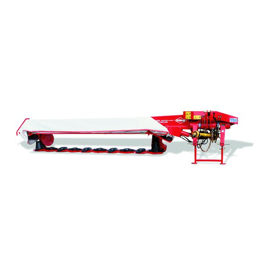
- Page 1 OPERATOR'S MANUAL KN045MGB G Read carefully before starting the machine Disc mower Original instructions KN045MGB G - English - 03-2016...
-
Page 3: Dear Owner
Designated use of the machine The GMD4410 mower must only be used for the purpose for which it was manufactured: mowing on the ground of hay fields, grass silage fields and improved pastures for the purpose of harvesting fodder for feeding livestock. -
Page 4: Table Of Contents
Disc mower GMD4410 2. Contents Dear Owner ........................1 Contents ..........................2 Identification of the machine..................5 Front view ............................5 Rear view ............................5 Model identification plate ......................... 6 Optional equipment.......................... 7 Safety..........................8 Description of symbols used in this document................. 8 Safety instructions ........................... 9 4.2.1... - Page 5 Disc mower GMD4410 Machine specifications....................31 Description and glossary ....................... 31 Technical specifications ......................... 32 Required equipment ........................33 5.3.1 Cutter bar ......................... 33 Sound levels ..........................34 Putting into service...................... 35 Description of control elements ..................... 35 Coupling and uncoupling ....................... 36 6.2.1...
- Page 6 Disc mower GMD4410 10. Maintenance and storage ....................68 10.1 Frequency chart ..........................68 10.2 Lubrication ............................. 69 10.2.1 PTO shaft.......................... 70 10.2.2 Oil ............................. 71 10.2.3 Grease..........................71 10.2.4 Oil change ........................72 10.3 Maintenance ..........................76 10.3.1 Hydro-pneumatic accumulator..................76 10.3.2 The side gearbox drive system..................
-
Page 7: Identification Of The Machine
Disc mower GMD4410 3. Identification of the machine Front view Rear view 3. - Identification of the machine KN045MGB G... -
Page 8: Model Identification Plate
Disc mower GMD4410 Model identification plate Please write below the type and serial number of the machine. This information is to be given to the Kuhn authorized dealer for any spare parts order or warranty claim. KUHN S.A. 67700 SAVERNE - FRANCE... -
Page 9: Optional Equipment
Disc mower GMD4410 Optional equipment Tick box corresponding to the equipment fitted on your machine: Side deflector kit. Raised skid shoes. Chain stroke limiter. Fast locking 1 3/8’’ - 6 spline yoke. Lateral signalling equipment (for France). -
Page 10: Safety
Disc mower GMD4410 4. Safety Description of symbols used in this document This symbol indicates a potentially hazardous situation that if not avoided, could result in serious bodily injury. This symbol is used to identify special instructions or procedures which, if not followed strictly, could result in machinery damage. -
Page 11: Safety Instructions
It is too late to learn once work has been started! Never let anyone operate the machine who is not trained to do so. Should you have any difficulties in understanding any parts of this manual, please contact your KUHN dealer. 4. - Safety KN045MGB G... -
Page 12: Precautions To Be Taken Before Carrying Out Any Operations On The Machine
Disc mower GMD4410 4.2.3 Precautions to be taken before carrying out any operations on the machine Before leaving the tractor or before adjusting, maintaining or repairing the machine, disengage the PTO drive, turn off the engine, remove ignition key and wait until all moving parts have come to a complete stop and apply park brake. -
Page 13: Precautions When Driving
Disc mower GMD4410 4.2.5 Precautions when driving Tractor handling, stability, performance and braking efficiency are all affected by weight distribution, trailed or mounted implements, additional ballast and driving conditions. It is therefore of great importance that the operator exercises caution in every given situation. -
Page 14: Precautions When Driving On Public Roads
Disc mower GMD4410 4.2.6 Precautions when driving on public roads Dimensions Depending on the dimensions of the machine, contact the relevant authorities to ensure that it can be legally transported on public roads. If the machine is over the maximum legal size, follow the local regulations for special transportation of oversize equipment. - Page 15 Disc mower GMD4410 Gross weight and weight per axle The drawings are not legally binding, their only aim is to illustrate the method to use. Prior to driving on public roads, check that all criteria are met to be in conformity with the...
- Page 16 Disc mower GMD4410 How to proceed: Stage 1: To measure: - Tractor tare (T). T = _____kg Stage 2: - Couple the machine to the tractor. To measure: - Load on front axle (t1): • Tractor + machine (transport position).
- Page 17 Disc mower GMD4410 Stage 3: To measure: - Total weight (t): • Tractor + machine (transport position). • Ballast weights. Checking: - To go to the next stage: • Check in the tractor's operator's manual that the value measured is below the tractor's Gross Combined Weight Rating.
-
Page 18: Maximum Speed
Disc mower GMD4410 4.2.7 Maximum speed - Always keep to the legal speed limit for driving a tractor-machine assembly on public roads. 4.2.8 Precautions when coupling Before attaching the machine, make sure that it cannot accidentally start moving (chock the wheels) and that the parking stand is in the right position. -
Page 19: Hydraulic Circuit
Disc mower GMD4410 4.2.9 Hydraulic circuit Caution! The hydraulic circuit is under high pressure. Maximum pressure at work: 200 bar (2900 psi). Before connecting hoses to the tractor hydraulics, ensure that tractor and machine circuits are not under pressure. Before disconnecting a hose, depressurize the hydraulic circuit. -
Page 20: Pto Shaft
Disc mower GMD4410 4.2.10 PTO shaft Use only PTO shafts supplied with the machine or recommended by the machine manufacturer. The protective shield of the tractor PTO stub, the PTO shaft guards and the protective shield of the machine input shaft must always be in place and in good condition. - Page 21 Disc mower GMD4410 Before engaging the PTO drive, make sure that there are no people or animals near the machine. Never engage the PTO drive when the tractor engine is stopped. Do not install any adapter device that results in a portion of the tractor PTO stub, the rotating PTO shaft, or the adapter to be unguarded.
-
Page 22: Precautions During Manoeuvres
Disc mower GMD4410 4.2.11 Precautions during manoeuvres When moving the machine from the transport position to the working position and vice versa, make sure that nobody is within the machine pivoting area. 4.2.12 Remote controlled components Danger of crushing and shearing can exist when components are operated by hydraulic or pneumatic controls. -
Page 23: Hydro-Pneumatic Accumulator
Disc mower GMD4410 4.2.15 Hydro-pneumatic accumulator hydro-pneumatic accumulator contains pressurized nitrogen and oil. There is an asphyxiation hazard in closed areas. Improper installation or handling can lead to serious accidents. Depressurize the gaz and oil sides of the hydraulic accumulator before opening it. -
Page 24: Precautions For Maintenance And Repair Work
For your own safety and for correct machine operation, only use original manufacturer parts. It is strongly recommended to have your machine checked by your Kuhn dealer after each season, especially tools and their attaching hardware. 4. - Safety KN045MGB G... -
Page 25: Projection Of Stones And Foreign Objects
Disc mower GMD4410 4.2.17 Projection of stones and foreign objects For driver safety, always use a tractor equipped with a cab. Keep the ground to mow free of foreign bodies. Avoid mowing on stony or rocky grounds. If this is not possible, take extra safety precautions,... -
Page 26: Precautions For Machine Use
Disc mower GMD4410 4.2.18 Precautions for machine use After each use, check the cutting tools (discs, knives) their attachment hardware accordance with the instructions given in the present manual. Immediately replace any worn, damaged or missing cutting tool or element. To do this, use the tool outfit supplied with the machine. -
Page 27: Location And Description Of Safety Decals On The Machine
Disc mower GMD4410 Location and description of safety decals on the machine 4.3.1 Location of safety decals 59900600 59900300 59900600 599011001 4. - Safety KN045MGB G... -
Page 28: Description Of Safety Decals
Disc mower GMD4410 4.3.2 Description of safety decals Operating instructions (1) The operators' manual contains all the information necessary for using the machine safely. It is imperative to read and comply with all instructions. Working on the machine (2) - Page 29 Disc mower GMD4410 Crushing area (4) Never operate in an area where there is a crushing risk before all moving parts have come to a complete stop. 59900300 Manoeuvring area (5) Stay a safe distance from the machine. Crushing hazard.
- Page 30 Disc mower GMD4410 Cutting tools (7) The cutting tools and their attachment hardware meet safety and reliability criteria set by standards and by the manufacturer. For your own safety and for correct machine operation, only use original manufacturer parts.
-
Page 31: Road Safety Equipment And Recommendations
GMD4410 Road safety equipment and recommendations The road safety equipment is mounted in the factory or by your authorized Kuhn dealer according to current safety regulations. The rear safety device comprises: • A signalling light (1). • A signalling panel (2). -
Page 32: Instructions Specific To France
Disc mower GMD4410 4.4.1 Instructions specific to France To conform with the current road regulations, the machine must be fitted with specific signalling panels when driving on public roads. 4. - Safety KN045MGB G... -
Page 33: Machine Specifications
Disc mower GMD4410 5. Machine specifications Description and glossary Parking stand Connecting frame Hitch pin Cutterbar Compensation cylinder Central gearbox Work/transport cylinder Lift cylinder Suspension circuit accumulator 10 : Transport lock 11 : Suspension circuit pressure gauge 12 : Front guard... -
Page 34: Technical Specifications
Disc mower GMD4410 Technical specifications GMD4410 Attachment type 3 point, Category 3 Number of discs Working width 4.35 m (14’7’’) Width in working position 5.30 m (17’5’’) Height in working position 1.40 m (4’7’’) Length in working position 1.77 m (5’10’’) Width in transport position 1.60 m (5’3’’) -
Page 35: Required Equipment
Disc mower GMD4410 Required equipment 5.3.1 Cutter bar - Knife attachment per bolt and nut. • Standard - Fast fit knives. 5. - Machine specifications KN045MGB G... -
Page 36: Sound Levels
Disc mower GMD4410 Sound levels Sound levels have been measured in accordance with the measuring methods as defined in: NF EN ISO 4254-1 «Agricultural machinery - Safety - Part 1: General requirements» Weighted equivalent continuous acoustic pressure level at the driver's seat (closed cabin) L (A) eq: Tractor only: 71.0 dB(A) -
Page 37: Putting Into Service
Disc mower GMD4410 6. Putting into service Description of control elements The machine is fitted with a release cord operated from the tractor cab. The machine is supplied with an 18 mm box wrench (1) to carry out certain adjustment and maintenance tasks. -
Page 38: Coupling And Uncoupling
Disc mower GMD4410 Coupling and uncoupling The machine adapts to tractors fitted with a 3 point linkage category 3. 6.2.1 Description of coupling elements • A PTO shaft 1 3/8’’ - 6 splines. • A release cord. • Two hydraulic hoses which control the machine transport/work position setting. -
Page 39: Preparing The Machine
Disc mower GMD4410 6.2.3 Preparing the machine Linkage adjustment - Measure dimension A. If measure A is comprised between 2.10 m and 2.30 m (6’11’’ - 7’7’’): - Place lower links in position a. - Adjust machine lower hitch pin position: •... - Page 40 Disc mower GMD4410 If measure A exceeds 2.30 m (7’7’’): - Place lower links in position b. - Adjust machine lower hitch pin position: • Unscrew the 8 bolts (3). • Position hitch pin (2) at measure A = 10 mm (0.4’’).
-
Page 41: Coupling The Machine
Disc mower GMD4410 6.2.4 Coupling the machine When optional equipment is used, follow specific procedures mentioned in the related section: Chain stroke limiter. - Lower the tractor three-point linkage. - Position ball joints of tractor lower links in line with machine lower yokes. - Page 42 Disc mower GMD4410 - Lift the machine using the tractor lift linkage until the parking stand no longer rests on the ground. - Remove locking pin (2). - Fold parking stand (1) upwards and lock it in place. 6. - Putting into service...
-
Page 43: Hydraulic Connections
Disc mower GMD4410 6.2.5 Hydraulic connections The machine hydraulic suspension circuit is pressurized at the factory. - Connect hydraulic hoses transport/work cylinder to a double acting valve (1). - Connect the mowing unit lift cylinder to a single acting valve (2). -
Page 44: Primary Pto Shaft
Disc mower GMD4410 6.2.7 Primary PTO shaft Make sure that the PTO shaft is correctly adjusted, to avoid premature wear and tear. The direction of rotation is shown on a decal. 1000 - Separate the two half PTO shafts and connect them to the machine's input shaft and to the tractor PTO stub. - Page 45 Disc mower GMD4410 Never operate the PTO shaft at an angle X exceeding 30°. To avoid serious accidents, the PTO drive shaft guards must be properly in place and fixed with the chains provided. - On machine side, attach guard chain to the headstock hole.
-
Page 46: Intermediate Pto Shaft
Disc mower GMD4410 6.2.8 Intermediate PTO shaft Before carrying out any maintenance or repairs on the machine, switch off the tractor engine, remove ignition key, wait until all moving parts have come to a standstill and apply park brake. ... - Page 47 Disc mower GMD4410 - Tighten nuts to release the friction discs. - Let the friction discs slip for a few seconds. - Thread nuts away until they bottom against the threaded studs. - Couple the intermediate PTO shaft on the central gearbox side.
-
Page 48: Adjusting The Machine
Disc mower GMD4410 On machine side, attach drive shaft guard chain (1) to the input shaft guard. Immediately replace any worn or damaged guard. The friction slip clutch is ready to function. 6.2.9 Adjusting the machine Positioning of lower links - Measure dimension E. - Page 49 Disc mower GMD4410 Hitch pin parallelism From the transport position: - Pull on cord to release latch. - Pressurize the transport/work position cylinder to place the mowing unit in working position. The machine is in headland turn position. - Measure and adjust the height of the hitch pins until the same measure is obtained on each side: •...
- Page 50 Disc mower GMD4410 Frame height and check chains. Tractor fitted with a hydraulic position control function: - Lower the tractor lift linkage so that hitch pins are at a distance H = 600 mm (2’) from the ground. - Note the corresponding lever position in the tractor cab.
-
Page 51: Uncoupling The Machine
Disc mower GMD4410 6.2.10 Uncoupling the machine For tractors not fitted with a hydraulic position control function, unhook and attach check chain to its support. - Place the machine in transport position. - Release and lower parking stand (1). - Secure parking stand using lock (2). -
Page 52: Instructions For Transport
Disc mower GMD4410 7. Instructions for transport Before placing the machine into transport position: - Check that nobody is within the machine pivoting area. - If there is someone, make sure the person moves away. Putting the machine into transport position From the working position: - Use mowing unit lift cylinder to lift the mowing unit. -
Page 53: Conformity With The Road Regulations
Disc mower GMD4410 Conformity with the road regulations Before driving the machine on public roads, ensure that the machine complies with current highway code regulations. - Check that the signalling panel is clean and that the lighting equipment functions before going on public roads. -
Page 54: Instructions For Work
Disc mower GMD4410 8. Instructions for work Before placing the machine in working position: - Check that nobody is within the machine pivoting area. - If there is someone, make sure the person moves away. Putting the machine into work... - Page 55 Disc mower GMD4410 The machine is in headland turn position. - Lower the mowing unit onto the ground using the mowing unit lift cylinder. - Shift the mowing unit lift cylinder directional control valve in float position. The machine is in working position.
-
Page 56: Adjustments In Working Position
Disc mower GMD4410 Adjustments in working position 8.2.1 Cutting height The desired cutting height is obtained directly by adjusting the top link length. The height can be adjusted between 30 and 60 mm (1.2’’ - 2.4’’) depending on the tractors. -
Page 57: Ground Pressure
Disc mower GMD4410 8.2.2 Ground pressure The ground pressure adjustment determins the safety breakback adjustment: • Example: when the pressure in the gauges increases, the mowing unit ground pressure decreases and the breakback force increases. The mowing unit suspension is obtained by a hydro- pneumatic accumulator. - Page 58 Disc mower GMD4410 Pressure adjustment Increase pressure in the hydro-pneumatic accumulator: - Place the machine in working position. The following adjustments do not cause the machine to move. 59951300 - Open the hydraulic valve using the 18 box spanner supplied with the machine (Position (a)).
- Page 59 Disc mower GMD4410 - When the required pressure is reached, close the valve (Position (b)). Position (a): Circuit open (Adjustment). Position (b): Circuit closed (Work and transport). The valve must only be in open position for pressure adjustments. 8. - Instructions for work...
-
Page 60: Transport Stabilizing Pressure
Disc mower GMD4410 8.2.3 Transport stabilizing pressure The mowing unit cushioning is obtained with an hydro-pneumatic accumulator. In modifying the accumulator's pressure, mowing unit's cushioning varies. To check the mowing unit's stabilizing pressure - Place the machine in transport position. - Page 61 Disc mower GMD4410 Pressure adjustment Increase pressure in the hydro-pneumatic accumulator: - Raise the machine in headland turn or transport position. The following adjustments do not cause the machine to move. 59951300 - Open the hydraulic valve using the 18 box spanner supplied with the machine (Position (a)).
-
Page 62: Swathing System
Disc mower GMD4410 8.2.4 Swathing system The swathing system comprises: • 2 swath wheel (Adjustable). The swath width is 3 m (9’10’’) approximately. Check that there is still a play (J) equalling minimum 20 mm (0.8’’) between the shell, the cone rib and the swath wheel. -
Page 63: Machine Use
Disc mower GMD4410 Machine use Before mowing and to reduce risks of projections, lower the front guard. Keep all persons and animals away from the machine danger zone. Never lean or step on the protection cover. Before the machine engages the crop:... -
Page 64: Front Guard Release
Disc mower GMD4410 8.3.1 Front guard release - Release and lift side guard using 18 mm box spanner supplied with the machine: • (a): Position wrench. • (b): Unlock hook. • (c): Lift up the front guard. 8.3.2 Drive speed Adapt the forward speed to the working conditions. -
Page 65: Optional Equipment
Disc mower GMD4410 9. Optional equipment Side deflector kit Kit no. 1066240 The side deflectors are recommended for mowing dense or down crops with long stems. - Fit the 2 side deflectors on the outer sides of the cutter bar holders. -
Page 66: Chain Stroke Limiter
Disc mower GMD4410 Chain stroke limiter Kit no. 1066360 This equipment enables adjusting the chassis height in the absence of a hydraulic stroke limiter with position indexation on the tractor. 9.3.1 Adjusting the machine The chain stroke limiter must be attached to the right hitch pin. -
Page 67: Fast Locking 1 3/8'' - 6 Spline Yoke
Disc mower GMD4410 Uncoupling the machine - Unhook chain stroke limiter (1). Fast locking 1 3/8’’ - 6 spline yoke Kit no. 4603256 A specific yoke is available as option for tractors equipped with a 1 3/8’’ - 21 spline pto stub. -
Page 68: Lateral Signalling Equipment (For France)
Disc mower GMD4410 Lateral signalling equipment (for France) Kit no. 1016420 The machine can be fitted with specific signalling lights to comply with the road regulations. Swath divider Kit no. 1066270 This equipment allows creating a separation in the swath in order to avoid rolling on the crop during the next pass. - Page 69 Disc mower GMD4410 9.6.1 Adjustment possibilities Lateral adjustment Allows increasing or reducing the swath separation width. - Unscrew the 2 nuts (1). - Slide the unit to one side or the other. - Tighten the 2 nuts (1). ...
-
Page 70: Maintenance And Storage
Disc mower GMD4410 10. Maintenance and storage Before leaving tractor before adjusting, maintaining or repairing the machine, disengage the PTO drive, turn off the engine, remove ignition key and wait until all moving parts have come to a complete stop and apply park brake. -
Page 71: Lubrication
Disc mower GMD4410 Grease: - The mowing unit compensation cylinder ball joint - The mowing unit pivot pin Maintenance and storage - Hydro-pneumatic accumulator 10.2 Lubrication Except for lubricating the pto shaft, the machine must always be placed in transport position for any maintenance (knife replacement, lubrication, etc). -
Page 72: Pto Shaft
Disc mower GMD4410 10.2.1 PTO shaft Primary PTO shaft - Every 100 hours: • universal joints (1). • transmission tube (2). • Guide rings (3). Intermediate PTO shaft - Every 100 hours: • universal joints (1). • transmission tube (2). -
Page 73: Oil
Disc mower GMD4410 10.2.2 Oil • The mowing unit lift cylinder ball joints (1). • The moving parts and pivot points. 10.2.3 Grease • The mowing unit compensation cylinder ball joint (1). • The mowing unit pivot pin. 10. - Maintenance and storage... -
Page 74: Oil Change
Disc mower GMD4410 10.2.4 Oil change The side angle gearbox Before draining oil, operate the machine for a few minutes so that the oil warms up. The angle gearbox is lubricated with 0.7 L (0.18 US gal) of extreme-pressure oil for mechanical transmissions with viscosity grade SAE 80W90 and API grade GL5. - Page 75 Disc mower GMD4410 Central gearbox Before draining oil, operate the machine for a few minutes so that the oil warms up. The main gearbox is lubricated with 2.3 L (0.6 US gal) of extreme-pressure gear oil with viscosity grade SAE 80W90 and API grade GL5.
- Page 76 Disc mower GMD4410 Cutterbar The cutterbar is lubricated for life and requires no periodic maintenance. If in doubt as to the oil quantity contained in the cutterbar, fully drain and refill cutterbar respecting recommended oil quantity and quality. Following all service operations or in case of an oil leak, empty and refill cutterbar.
- Page 77 Disc mower GMD4410 - Place a container of sufficient capacity under drain plug. - Raise cutterbar on opposite side of drain plug. - Remove drain plug (1) and its washer. - Allow oil to drain completely. - Wait for dripping to stop.
-
Page 78: Maintenance
Disc mower GMD4410 10.3 Maintenance Before carrying out any maintenance or repairs on the machine, switch off the tractor engine, remove ignition key, wait until all moving parts have come to a standstill and apply park brake. 10.3.1 Hydro-pneumatic accumulator... - Page 79 Disc mower GMD4410 Depressurize the hydraulic circuit Suspension hydraulic circuit - Stop the tractor engine. - Open valve (position a). - Operate transport/work position cylinder transport position direction. Release pressure until the gauge needle reads 0. - When the pressure reaches 0 bar (0 psi) bar on the pressure gauge, close the valve (position b).
- Page 80 Disc mower GMD4410 Mowing unit hydraulic suspension circuit - Stop the tractor engine. - Open valve (position a). - Activate the headland turn cylinder control valve in the lower into work position. Release pressure until the gauge needle reads 0.
-
Page 81: The Side Gearbox Drive System
Disc mower GMD4410 10.3.2 The side gearbox drive system - Following all service operations on the drive system, check that the distance between the side gearbox drive shaft and the upper side of the cutterbar stiffener equals measure A: +/- 4 mm (0.15’’) •... -
Page 82: Work/Transport Cylinder
Disc mower GMD4410 Adjustment: The transport stop (1) limits the machine's oscillation during transport. - Loosen counter nut (2). - Bring stop (1) in contact with damper (3). - Give transport stop (1) one or two preload turns. - Tighten counter nut (2). -
Page 83: Mowing Unit Locking Cylinder
Disc mower GMD4410 10.3.5 Mowing unit locking cylinder The mowing unit locking cylinder is fitted with an air- operated chamber that allows immediate mowing unit reaction with regards to irregular ground contours. Check the pressure: - Place the machine in working position or parking position. -
Page 84: Inspection Of Knives And Securing Elements
Disc mower GMD4410 10.3.6 Inspection of knives and securing elements Immediately replace worn or damaged parts with genuine KUHN parts. When the following equipment is fitted: Knife attachment per bolt and nut Knives - Inspect systematically all knives before the machine is operated to: •... - Page 85 Disc mower GMD4410 Always replace both knives per disc to avoid creating an out-of-balance force. 10. - Maintenance and storage KN045MGB G...
- Page 86 Disc mower GMD4410 Securing elements - Check the securing elements: • After hitting an obstacle. • When replacing knives. • At the beginning of each season. - The fixing bolts should be changed in the following cases: • When there is visible distortion.
- Page 87 Disc mower GMD4410 Knife replacement Replace knife lock-nuts and bolts when they have been removed 5 times. Replace immediately all worn or distorted knives. Never straighten a bent knife. Always replace both knives per disc. - Clean the nut case.
- Page 88 Disc replacement Inner disc: The replacement of the inner disk must be carried out by your Kuhn authorized dealer. Intermediate discs: - Place a wooden wedge (1) between two discs to stop them from moving. - Remove the 4 bolts (2) and their conical washers.
- Page 89 Disc mower GMD4410 Reinstalling - Refit the disc (2). - Respect disc direction of rotation according to fitting of knives. Make sure the arrow on the knife upper face is pointing in the disc's direction of rotation. - Reinstall disc cover (1).
- Page 90 Disc mower GMD4410 - Place a wooden wedge (1) between two discs to stop them from moving. - Torque bolts to (2) : • Torque: 12 daN m (89 lbf ft). - Remove locking piece. Check that there is a minimum play of 1 mm (0.04’) between the knife attachment...
- Page 91 Disc mower GMD4410 When the following equipment is fitted: Fast fit knives Knives - Inspect systematically all knives before the machine is operated to: • ensure the cutting quality. • ensure safety in use. • Prevent cutterbar damage risks.
- Page 92 Disc mower GMD4410 The hole L for the securing bolt must not become oval by more than 22 mm (0.87’’). Always replace both knives per disc to avoid creating an out-of-balance force. 10. - Maintenance and storage KN045MGB G...
- Page 93 Disc mower GMD4410 Securing elements - Check the securing elements: • After hitting an obstacle. • When replacing knives. • At the start of each season. - The fixing bolts should be changed in the following cases (2): • When there is visible distortion.
- Page 94 Disc mower GMD4410 The radial play between a worn bolt and a new knife must not exceed d = 10 mm (0.4’’). - Replace nuts in the following cases: • When nut wear reaches a = 5 mm (0.2’’). Check the condition of the securing elements...
- Page 95 Disc mower GMD4410 Knife replacement Before carrying out any maintenance or repairs on the machine, switch off the tractor engine, remove ignition key, wait until all moving parts have come to a standstill and apply park brake. Replace immediately all worn or distorted knives.
- Page 96 Disc mower GMD4410 - Pivot special tool downwards to free spring plate from screw head. - Make sure that the securing nut and bolt are in good condition and if necessary, replace them. • Torque: 12 daN m (89 lbf ft).
- Page 97 Disc mower GMD4410 - Pivot special tool downwards to free spring plate from screw head. - Insert the new knife on the screw head. Press knife upwards and pull it towards yourself before releasing the special tool. - (a), (b), (c) Checking the full locking and free rotation of the knife on the screw head.
- Page 98 Disc mower GMD4410 - Check that screw head (2) is free to slide in spring plate hole (3). - Remove special tool. - Rotate disk by half a turn. - Repeat previous tasks. - Repeat previous tasks on the other disks.
- Page 99 Disc replacement Inner disc: The replacement of the inner disk must be carried out by your Kuhn authorized dealer. Intermediate discs: - Place a wooden wedge (1) between two discs to stop them from moving. - Remove the 4 bolts (2) and their conical washers.
- Page 100 Disc mower GMD4410 Reinstalling - Refit the disc (2). - Respect disc direction of rotation according to fitting of knives. Make sure the arrow on the knife upper face is pointing in the disc's direction of rotation. - Reinstall disc cover (1).
- Page 101 Disc mower GMD4410 - Position conical centre of washers at the top. - Place a wooden wedge (1) between two discs to stop them from moving. - Torque bolts to (2) : • Torque: 12 daN m (89 lbf ft).
- Page 102 Disc mower GMD4410 Check that there is a minimum play of X = 1 mm (0.04’’) between the spring plate and the cutter bar skids. Otherwise, position spacer(s) (two maximum) between the housing and the spring plate. 10. - Maintenance and storage...
-
Page 103: Outer And Inner Cones
GMD4410 Spring plate replacement Inner disc: The replacement of the inner disc spring plate must be carried out by a Kuhn authorized dealer. Intermediate discs: - Remove the disc: • See section: ’’Disc replacement’’. - Remove spring plate (1). -
Page 104: Storage
Disc mower GMD4410 10.4 Storage 10.4.1 At the end of each season - Clean the machine thoroughly. - Fully lubricate the machine. - Drain and refill gearboxes with new oil: See section ’’Lubrication’’. - Touch up any areas of damaged paintwork. -
Page 105: Troubleshooting Guide
Disc mower GMD4410 11. Troubleshooting guide Problem Cause Remedy Dull or broken knives. Replace knives. Make sure the arrow on Knives not installed the knife upper face is Uneven stubble. correctly. pointing in the disc's direction of rotation. - Page 106 Disc mower GMD4410 Incorrect main frame Adjust main frame height setting. with regards to the ground. Bad ground contour Excessive ground speed. Reduce groundspeed. adaptation. Insufficient ground Reduce accumulator pressure. pressure. Incorrect tractor lift linkage See machine attachment. setting. Insufficient cutterbar...
-
Page 107: Appendix
Disc mower GMD4410 12. Appendix 12.1 Calculating the load on an axle When coupling a tool to the front and/or rear 3-point lift linkage, the maximum authorized payload must not be exceeded. When coupling tools to the front and/or rear 3-point lift linkages, the maximum load on tractor's tires must not be exceeded The load on the tractor front axle must always represent 20 % of the tractor unladen weight. - Page 108 Disc mower GMD4410 Obtained Description Units Description Tractor unladen weight Unladen load on tractor front axle Empty load on tractor rear axle Axle loads (Tractor + machine) Load on front axle (Tractor + machine) Load on rear axle (Tractor + machine)
- Page 109 Disc mower GMD4410 Front tool: 2) Calculation of the minimum rear ballast weight M2 minimum M1 x a - T2 x b + 0.45 x T x b minimum = b+c+d Write the minimal additional weight in the chart. 3) Calculation of the actual load on the front axle T1...
- Page 110 Disc mower GMD4410 Table: Actual value obtained Value authorized Double value of the by calculation according to authorized capacity operator's manual per tyre (2 tyres) Minimum front/rear ballasting Total weight < Load on front axle < < Load on rear axle <...
- Page 111 Disc mower GMD4410 Determining the machine weight (M2) and the position of its centre of gravity (d) If the data required to calculate the total weight, axle loads and minimum ballasting are not supplied, use the following method. - Tractor only: - T1: Load on front axle.
- Page 112 Disc mower GMD4410 - T: Axle loads. • Tractor only. T = _____kg 12. - Appendix KN045MGB G...
- Page 113 Disc mower GMD4410 Rear tool or front-rear combination: If the total unit weight exceeds the tractor Gross Combined Weight Rating in accordance with the countrie's legislation, empty the hopper to travel on public roads. In any case, we recommend to travel on public roads with empty hoppers and tanks.
- Page 114 Disc mower GMD4410 - t: Axle loads. • Tractor + machine. • Hopper empty! t = _____kg Calculating the rear tool weight (M2): M2 = t - T Calculating the distance (d): d = (( b x ( T1 - t1)) / M2 ) - c 12.
-
Page 115: Limited Warranty
KUHN equipment from an authorized KUHN dealer, that such equipment is, at the time of delivery to such purchaser, free from defects in material and workmanship, and that such equipment is covered under this Limited Warranty providing the machine is used and serviced in accordance with the recommendations in the Operator's manual. - Page 116 - The warranty claim is completed on line via extranet - www.kuhn.com or submitted on a KUHN warranty claim form and returned to the Company within one month after the date of failure or the date of problem becoming apparent.
- Page 117 $Specimen of the "Declaration of conformity" EC Declaration of conformity (European directive 2006/42/CE) The manufacturer: Manufacturer name and address declares that the product described hereafter: Brand Brand Machine Machine Type / Model : Type / Model Serial no. Serial no. - conforms to the requirements of the European directive 2006/42/CE.
- Page 120 KUHN S.A. - B.P. 50060 - F - 67706 SAVERNE CEDEX (FRANCE) KUHN-AUDUREAU S.A. - B.P. 19 - F - 85260 LA COPECHAGNIERE (FRANCE) KUHN-BLANCHARD SAS - 24, route de Nantes - F - 44680 CHEMERE (FRANCE) KUHN-HUARD S.A. - B.P. 49 - F - 44142 CHATEAUBRIANT CEDEX (FRANCE) KUHN-GELDROP B.V.
Need help?
Do you have a question about the GMD4410 and is the answer not in the manual?
Questions and answers