Sign In
Upload
Download
Table of Contents
Contents
Add to my manuals
Delete from my manuals
Share
URL of this page:
HTML Link:
Bookmark this page
Add
Manual will be automatically added to "My Manuals"
Print this page
×
Bookmark added
×
Added to my manuals
Manuals
Brands
Optomed Manuals
Medical Equipment
Smartscope PRO
User manual
Optomed Smartscope PRO User Manual
Hide thumbs
Also See for Smartscope PRO
:
General use
(19 pages)
1
2
3
Table Of Contents
4
5
6
7
8
9
10
11
12
13
14
15
16
17
18
19
20
21
22
23
24
25
26
27
28
29
30
31
32
33
34
35
36
37
38
39
40
41
42
43
44
45
46
47
48
49
50
51
page
of
51
Go
/
51
Contents
Table of Contents
Bookmarks
Table of Contents
Quick Start Guide
Table of Contents
1 Indications for Use
2 Contraindications for Use of the Optics Modules EY4, FA and ES2
3 Warnings and Cautions
4 Important Symbols
5 Parts of the Device
6 Usage Environment Requirements
7 Operating Instructions
Preparations
Connection to a PC
Pay-Per-Study
Basic Use - Starting Up, Shutting down and Taking an Image
Image Quality Analysis
Attaching and Detaching Optics Module
Device Menu
Patient Editor
Adding New Patient
Patient Folder Linking
Patient List Exporting
Adjusting Focus and Automatic Focus
Reset Button
8 Retinal Imaging Using Optics Module Smartscope EY4
9 Eye Imaging Using Anterior Ophthalmic Module Smartscope ES2
10 Fluorescein Angiography Imaging Using Optics Module Smartscope FA
11 Error Messages
12 Cleaning Instructions
13 Device Maintenance
14 Technical Description
15 Warranty
Appendix A - Electromagnetic Compatibility Information
Appendix B - Replacing the Battery
Appendix C - WLAN Functionality
Installing / Uninstalling
Operation
WLAN SD Card Firmware Update
Advertisement
Quick Links
1
Quick Start Guide
2
Parts of the Device
3
Connection to a Pc
4
Error Messages
5
Appendix C - Wlan Functionality
Download this manual
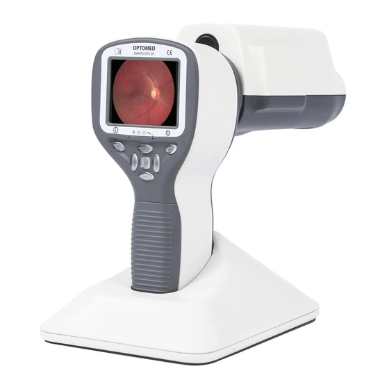
USER'S MANUAL
Optomed Smartscope PRO
& Smartscope FA
Optomed SMARTSCOPE PRO & SMARTSCOPE FA are manufactured by
Optomed Ltd.
Place of Business:
Optomed Ltd
Yrttipellontie 1
FI-90230 Oulu
Finland
Manual version: Rev 17.0
Date: 2019 09 30
Page 1 of 51
Table of
Contents
Previous
Page
Next
Page
1
2
3
4
5
Advertisement
Table of Contents
Need help?
Do you have a question about the Smartscope PRO and is the answer not in the manual?
Ask a question
Questions and answers
Related Manuals for Optomed Smartscope PRO
Medical Equipment Optomed Smartscope General Use
With m5 (19 pages)
Medical Equipment Optomed SMARTSCOPE PRO - Simply Brilliant Troubleshooting Manual
(31 pages)
Medical Equipment Optomed Aurora Quick Manual
(4 pages)
Medical Equipment Optomed Aurora User Manual
(48 pages)
Medical Equipment Optomed AURORA AEYE User Manual
(78 pages)
Medical Equipment Optomed AURORA User Manual
(60 pages)
Medical Equipment Optomed HALO User Manual
Automated portable retinal camera (64 pages)
Medical Equipment Optomed AURORA IQ Quick Manual
(4 pages)
Medical Equipment Optomed Polaris User Manual
(63 pages)
Medical Equipment Optomed AURORA AEYE Quick Start Manual
(8 pages)
This manual is also suitable for:
Smartscope fa
Smartscope m5
Smartscope ey4
Smartscope es2
Table of Contents
Print
Rename the bookmark
Delete bookmark?
Delete from my manuals?
Login
Sign In
OR
Sign in with Facebook
Sign in with Google
Upload manual
Upload from disk
Upload from URL


Need help?
Do you have a question about the Smartscope PRO and is the answer not in the manual?
Questions and answers