Table of Contents
Advertisement
Quick Links
Valve terminal types 03...05
with field bus node or control block
Supplementary description of I/O modules
Input modules:
Output modules:
Additional power supply:
High current output modules:
Multi-I/O modules:
Type VIGE-03-FB-...-...
Type VIGA-03-FB-...-...
Type VIGV-03-FB-24V-25A
Type VIGA-03-FB-...-...H
Type VIEA-03-FB-12E-8A-...-SUBD
9909d
Advertisement
Chapters
Table of Contents

Subscribe to Our Youtube Channel
Related Manuals for Festo VIGE-03-FB Series


Summary of Contents for Festo VIGE-03-FB Series
- Page 1 Valve terminal types 03...05 with field bus node or control block Supplementary description of I/O modules Input modules: Type VIGE-03-FB-...-... Output modules: Type VIGA-03-FB-...-... Additional power supply: Type VIGV-03-FB-24V-25A High current output modules: Type VIGA-03-FB-...-...H Multi-I/O modules: Type VIEA-03-FB-12E-8A-...-SUBD 9909d...
- Page 2 Festo, Dept. KI-TD Type: DUCOM Edition: 9909d © (Festo AG & Co., D-73726 Esslingen, Federal Republic of Germany, 1999) The copying, distribution and utilization of this docu- ment as well as the communication of its contents to others without expressed authorization is prohibited. Of- fenders will be held liable for the payment of damages.
- Page 3 Order no.: 371 190 Title: Manual Designation: P.BE-VIEA-GB VIEA-03...05 9909d...
-
Page 4: Table Of Contents
Contents Designated use..........V Target group . - Page 5 High-current output modules (2A) ..... 4-1 Function ......... . . 4-3 Fitting .
-
Page 6: Designated Use
The I/O modules described in this manual have been designed exclusively for use in conjunction with valve terminals types 03, 04B and 05 from Festo. The I/O modules and their cables may only be used as follows: – as intended –... - Page 7 (protection against direct and indirect contact) in accordance with EN 60204-1/IEC 204 is guaranteed on Festo valve terminals. Safety transformers with the ad- jacent designation must be used for supplying PELV networks. The valve terminals must be earthed in order to ensure their function (e.g.
-
Page 8: Target Group
Target group This manual is directed exclusively at qualified person- nel trained in control and automation technology. Important user instructions Danger This manual contains instructions on the possible categories dangers which can occur, if the I/O modules are not used correctly. These instructions are printed in italics, are surrounded by a frame and also marked with a picto- gram. - Page 9 Pictograms Pictograms and symbols complement the danger warn- ings and draw attention to the nature and consequences of the dangers. The following pictograms are used: Uncontrolled movements of loose tubing. Undesired movements of the connected actuators. High electric voltage or undefined switching states of the electronic components which can affect connected circuits.
-
Page 10: Notes On This Manual
Notes on this manual I/O modules are available in both the PNP design (posi- tive logic) and the NPN design (negative logic). This manual supplements the ”Electronics manual.” It con- tains important information on the method of operation, fitting, installation and commissioning of the following modules: This manual deals with the: Input modules... - Page 11 This manual deals with the (cont.): Additional supply modules - VIGV-03-FB-24V-25A High-current output modules PNP: - VIGA-03-FB-4-PH NPN: - VIGA-03-FB-4-NH Multi I/O modules PNP: - VIEA-03-FB-12E-8A-SUBD NPN: - VIEA-03-FB-12E-8A-N-SUBD VIEA-03...05 9909d...
-
Page 12: Input Modules
1. Input modules Chapter 1 Input modules Types - VIGE-03-FB-4 - VIGE-03-FB-8 - VIGE-03-FB-8.1 - VIGE-03-FB-4-5POL - VIGE-03-FB-8-5POL - VIGE-03-FB-8-5POL-S - VIGE-03-FB-8.1-5POL - VIGE-03-FB-4-N - VIGE-03-FB-8-N VIEA-03...05 9909d... - Page 13 1. Input modules Contents Input modules ........1-1 Function of the input modules .
-
Page 14: Function Of The Input Modules
1. Input modules 1.1 Function of the input modules Input modules provide digital inputs in the valve termi- nal for connecting sensors and thereby enable e.g. cy- linder positions to be interrogated. A distinction is made between the following types: Type Explanation - VIGE-03-FB-4... -
Page 15: Display And Connecting Elements
Sensor connections 4 or 5-pin with 1 or 2 inputs Red diagnosis LED for short circuit/overload in the sensor power Fig. 1/1: Display and connecting elements Recommendation for the 8-input module (only 4-pin): Use the Festo DUO cable for connecting two sensors with one plug. VIEA-03...05 9909d... -
Page 16: Fitting
1. Input modules 1.2 Fitting WARNING Before starting the fitting work, switch off the following: • the compressed air supply • the operating voltage supply for the electronic components (pin 1) You can thereby avoid: – uncontrolled movements of loose tubing –... - Page 17 1. Input modules PLEASE NOTE Treat all the modules and components of the valve terminal with great care. Pay attention in particular to the following: • the screw connectors must be fitted correctly and not subjected to mechanical stress • the screws must be inserted correctly (otherwise the thread may be damaged) •...
- Page 18 1. Input modules Fitting (see also following diagram) PLEASE NOTE • Place modules ordered at a later date after the last module before the end plate. • Do not fit more than 12 electric modules. Fit the modules as follows: •...
-
Page 19: Installation
1. Input modules 1.3 Installation 1.3.1 Connecting sensors to input modules Pin assignment of 4-pin inputs The diagram below shows as an example the pin assign- ment of the 4-pin inputs. Pin assignment 4 inputs Pin assignment 8 inputs not con- Input Ex+1 nected + 24 V... -
Page 20: Pin Assignment 5-Pin Inputs
1. Input modules Pin assignment 5-pin inputs The diagram below shows as an example the pin assign- ment of the 5-pin inputs. Pin assignment 4 inputs Pin assignment 8 inputs not con- Input Ex+1 nected + 24 V Input Ex + 24 V Input Ex not con-... -
Page 21: Internal Structure Of Vige-03-Fb-4 And Vige-03-Fb-4-5Pol (Pnp Inputs)
1. Input modules Internal structure of VIGE-03-FB-4 and VIGE-03-FB-4-5POL (PNP inputs) 24 V ± 25 % Pin 1 Pin 2 Pin 5 " Pin 4 Pin 3 Pin 2 = not connected Ex = Input x Pin 5 = Earth connection; only with type VIGE-03-FB-...-5POL "... -
Page 22: Examples Of Circuitry Vige-03-Fb-4 And Vige-03-Fb-4-5Pol (Pnp Inputs)
1. Input modules Examples of circuitry VIGE-03-FB-4 and VIGE-03-FB-4-5POL (PNP inputs) Pin assignment Pin 3: 0 V Pin 2: not connected Pin 1: 24 V Pin 4: Input Ex Examples of circuitry AAAA AAAA AAAA " AAAA AAAA AAAA AAAA AAAA AAAA AAAA... -
Page 23: Internal Structure
1. Input modules Internal structure VIGE-03-FB-8, VIGE-03-FB-8-8.1, VIGE-03-FB-8-5POL and VIGE-03-FB-8.1-5POL (PNP inputs) 24 V ± 25 % Pin 1 Pin 2 " Pin 4 Pin 3 Pin 5 PLC/I-PC input x+1 (via field bus) Green LED Ex Logic identifier Ex+1 Pin 5 = Earth connection;... -
Page 24: Internal Structure Vige-03-Fb-8-5Pol-S(Pnp Inputs)
1. Input modules Internal structure VIGE-03-FB-8-5POL-S(PNP inputs) 24 V ± 25 % & Pin 1 Pin 2 " Pin 4 Pin 3 Pin 5 PLC/I-PC input x+1 (via field bus) Pin 5 = Earth connection; only with & Logic identifier Ex+1 type VIGE-03-FB-...-5POL "... -
Page 25: Examples Of Circuitry
AAAA AAAA Pin 5 = Earth connection; only with type VIGE-03-FB-...-5POL Ex = Input x 2-way distributor (T-piece e.g. Festo Duo cable; only 4-pin " Sensor 2 (Ex+1) (positive logic) Sensor 1 (Ex) (positive logic) Fig. 1/9: Examples of circuitry, 4-pin and 5-pin inputs (PNP 8 inputs) 1-14 VIEA-03...05 9909d... -
Page 26: Internal Structure Vige-03-Fb-4-N (Npn Inputs)
1. Input modules Internal structure VIGE-03-FB-4-N (NPN inputs) Pin 3 Pin 2 Pin 4 " 24 V ± 25 % Pin 1 Pin 2 = not connected Ex = Input x PLC/I-PC Ex (via field bus) " Logic identifier Ex Green LED Ex Fig. -
Page 27: Examples Of Circuitry Vige-03-Fb-4 (Npn Inputs)
1. Input modules Examples of circuitry VIGE-03-FB-4 (NPN inputs) Pin assignment Pin 2: not Pin 3: 0 V connected Pin 1: 24 V Pin 4: Input Ex Examples of circuitry Three-wire sensor (negative logic) Ex = Input x Two-wire sensor (negative logic) Contact Fig. -
Page 28: Internal Structure Vige-03-Fb-8, (-8.1) (Npn Inputs)
1. Input modules Internal structure VIGE-03-FB-8, (-8.1) (NPN inputs) Pin 3 Pin 2 Pin 4 " 24 V ± 25 % Pin 1 " PLC/I-PC Ex+1 (via field bus) PLC/I-PC Ex (via field bus) Logic identifier Ex+1 Logic identifier Ex Green LED Ex+1 Green LED Ex Fig. -
Page 29: Examples Of Circuitry Vige-03-Fb-8 (Npn Inputs)
AAAA AAAA AAAA AAAA AAAA AAAA 2-way distributor (T-piece e.g. Festo Duo cable; only 4-pin Ex = Input x Sensor 2 (Ex+1) (negative logic) Sensor 1 (Ex) (negative logic) Fig. 1/13: Examples of circuitry, 4-pin inputs (NPN 8 inputs) 1-18... -
Page 30: Commissioning
1. Input modules 1.4 Commissioning Next to the sensor connections there is/are one/two green LED(s). These indicate the status of the signal at the relevant output. The meaning of the LED is as fol- lows: Status LED Sequence Status logic 1 (signal present) LED lights up logic 0... - Page 31 1. Input modules PLEASE NOTE: Observe the following when using this module: – In the event of a short circuit all 8 sensor power supplies will be switched off together. – When the short circuit has been eliminated, the sensor power supply will be switched on again automatically.
-
Page 32: Technical Specifications
1. Input modules 1.6 Technical specifications Technical specifications VIGE-03-FB-... VIGE-03-FB-...-N (PNP, 4-pin) (NPN, 4-pin) Temperature range: - operation C ... + 50 - storage/transport C ... + 60 Relative humidity 95% non condensing Protection class as per EN 60 529 IP 65 Plug connector inserted or fitted with protective cap... - Page 33 1. Input modules Technical specifications VIGE-03-FB-... 5POL (PNP, 5-pin) Temperature range: - operation C ... + 50 - storage/transport C ... + 60 Relative humidity 95% non condensing Protection class as per EN 60 529 IP 65 Plug connector inserted or fitted with protective cap Electromagnetic compatibility - interference radiated...
-
Page 34: Output Modules
2. Output modules Chapter 2 Output modules Types - VIGA-03-FB-4 - VIGA-03-FB-4-5POL VIEA-03...05 9909d... - Page 35 2. Output modules Contents Output modules Types VIGA-03-FB-4, VIGA-03-FB-4-5POL ..... 2-1 Function of the output modules ..... . . 2-3 2.1.1 Display and connecting elements.
-
Page 36: Function Of The Output Modules
2. Output modules 2.1 Function of the output modules There are four transistor outputs on the output modules of the valve terminal for controlling low-current consum- ing devices (e.g. lights, further valves, etc.). Type Explanation - VIGA-03-FB-4 Provides 4 PNP outputs; 4-pin connections via 4 sockets with M12 thread - VIGA-03-FB-4-5POL... -
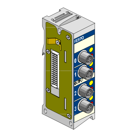
Page 37: Display And Connecting Elements
2. Output modules 2.1.1 Display and connecting elements There are four transistor outputs on the output modules of the valve terminal for your applications. The outputs have positive logic (PNP outputs). Example Output module " Type plate Yellow LED (switching status per output) "... -
Page 38: Fitting
2. Output modules 2.2 Fitting See Chapter 1.2 2.3 Installation WARNING Before starting installation and maintenance work, switch off the following: • the compressed air supply • the operating voltage for the electronic components (pin 1) • the operating voltage for the outputs/valves (pin 2). - Page 39 2. Output modules Pin assignment of 4-pin outputs The diagram below shows as an example the pin as- signment of the 4-pin outputs. Pin assignment 4-pin outputs not con- nected not con- nected Output Ax not con- nected not con- nected Output Ax+1 not con-...
- Page 40 2. Output modules Pin assignment of 5-pin outputs By means of internal connections, two outputs can be connected to each of the output sockets 0 and 2. Pin assignment 5-pin outputs Ax+1 connected Output Ax connected Output Ax+1 connected Ax+3 connected Output Ax+2 connected...
- Page 41 2. Output modules Internal structure VIGA-03-FB-4 24 V ± 10 % Pin 1 Pin 2 Pin 4 " Pin 3 " PLC/I-PC Ax (via field bus) Diagnosis Output driver - output status not connected - overload Red LED Yellow LED Fig.
- Page 42 2. Output modules Internal structure VIGA-03-FB-4-5POL 24 V ± 10 % " Pin 1 Pin 2 Pin 4 Pin 3 & Pin 5 PLC/I-PC Ax (via field bus) Diagnosis Output driver - output status " not connected - overload – connection 0, 2: Ox+1 Red LED &...
- Page 43 2. Output modules Examples of circuitry VIGA-03-FB-4 and VIGA-03-FB-4-5POL (PNP outputs) Pin assignment Pin 2: Pin 3: 0 V Pin 1: not Pin 4: Output Ax connected Examples of circuitry " + 24 V With type VIGA-03-FB4: free Ax = Output x With type VIGA-03-FB4-5POL: –...
-
Page 44: Commissioning
2. Output modules 2.4 Commissioning Yellow There is a yellow LED next to each of the connections status display for the actuators. This LED shows the status of the signal at the relevant output. The LED indicates the following: Status LED Sequence Status Output supplies a 1-signal... - Page 45 2. Output modules Faults at an output are indicated by means of the red error LED error LED. The LED indicates the following: Error LED Sequence Operating status Error treatment No short circuit/ none overload at output LED is Short circuit/ Eliminate short overload at output circuit/overload...
-
Page 46: Technical Specifications Types Viga-03-Fb-4 And Viga-03-Fb-4-5Pol (Pnp Outputs)
2. Output modules 2.5 Technical specifications types VIGA-03-FB-4 and VIGA-03-FB-4-5POL (PNP outputs) Technical specifications Type VIGA-03-FB-4 Temperature range: - operation C ... + 50 - storage/transport C ... + 70 Relative humidity 95% non condensing Protection class as per EN 60 529 IP 65 Plug connector inserted or fitted with protective cap... - Page 47 2. Output modules Technical specifications Type VIGA-03-FB-4-5POL Temperature range: - operation C ... + 50 - storage/transport C ... + 70 Relative humidity 95% non condensing Protection class as per EN 60 529 IP 65 Plug connector inserted or fitted with protective cap Electromagnetic compatibility - interference radiated...
-
Page 48: Additional Power Supply 24 V/25 A
3. Additional power supply 24 V/25 A CHAPTER 3 Additional power supply 24 V/25 A Type VIGV-03-FB-24V-25A VIEA-03...05 9809c... - Page 49 3. Additional power supply 24 V/25 A Contents Additional power supply 24 V/25 A Type VIGV-03-FB-24V-25A ........3-1 Function.
-
Page 50: Function
3. Additional power supply 24 V/25 A 3.1 Function PLEASE NOTE The additional current/voltage supply can only be used by the high-current output modules (HC-OUTPUT and HC-OUTPUT-N). The additional supply and the high-current output modules enable an additional 24 V/25 A to be made available for devices with higher current consumption. -
Page 51: Fitting
3. Additional power supply 24 V/25 A 3.2 Fitting PLEASE NOTE Treat all the modules and components of the valve terminal with great care. • With the high current contacts check that: – sockets are fitted correctly (danger of damage). –... - Page 52 3. Additional power supply 24 V/25 A Modules: 1 " Modules I/O modules 4/8 inputs (PNP/NPN) or 4 outputs (only PNP 0.5 A) or multi I/O module 12I/8O HC output (PNP/NPN) High-current supply (grey connection) ends after last HC output module "...
- Page 53 3. Additional power supply 24 V/25 A High-current contacts/sockets Fig. 3/2: Position of high-current contacts/sockets VIEA-03...05 9809c...
- Page 54 3. Additional power supply 24 V/25 A The following applies for the additional power supply module: – it can be fitted in any position to the left of the node – several additional supply modules are possible per terminal The following applies to the high-current output mo- dules: –...
-
Page 55: Installation
3. Additional power supply 24 V/25 A 3.3 Installation CAUTION Switch off the following before undertaking installation and/or maintenance work: • the compressed air supply • the operating voltage supply on the node of the terminal (pin 1, electronic components and pin 2, outputs/valves) •... -
Page 56: Selecting The Cable
3. Additional power supply 24 V/25 A 3.3.1 Selecting the cable PLEASE NOTE The tables and formulae in the "Electronics Manual" cannot be used for the additional supply cables. Note that the current consumption of the additional supply can amount to 25 A. •... -
Page 57: Connecting The Additional Supply
3. Additional power supply 24 V/25 A 3.3.2 Connecting the additional supply The outputs of the high-current output modules are supplied with 24 V via this connection. The modules must be fitted without gaps to the left of the additional supply. - Page 58 3. Additional power supply 24 V/25 A Pin assign- The diagram below shows the pin assignment of the ment connections for the additional supply (with cover removed). Connecting pins Flat fuse 25 A (automotive fuse): see Technical specifications Fig. 3/3: Pin assignment of additional supply 3-11 VIEA-03...05 9809c...
-
Page 59: Fitting The Cover
3. Additional power supply 24 V/25 A 3.3.3 Fitting the cover 1. Insert the seal of the cover. 2. Screw the threaded connector into the cover. 3. Push the screw connector, metal disc and strain relief onto the cable. 4. Push the cover onto the cable. "... -
Page 60: Connecting The Cable
3. Additional power supply 24 V/25 A 3.3.4 Connecting the cable 1. Remove approx. 5 cm of the cable coating. 2. Remove approx. 5 mm of the insulation, fit end sleeves onto the wire strands. 3. Connect the ends of the cables to the terminal pin, making sure that proper contact is made. -
Page 61: Example Of Circuitry
3. Additional power supply 24 V/25 A Example of circuitry Valve terminal with two additional supplies: – one with voltage which can be switched off separately; – the other with voltage which cannot be switched off separately. 2 1 3 24 V ±25 % 24 V ±10 % 3,15 A... -
Page 62: Commissioning Instructions
3. Additional power supply 24 V/25 A 3.4 Commissioning instructions Switching on the operating voltage The valve terminal can also be commissioned when the voltage for the additional supply is switched off. CAUTION The voltage for the internal electronic components in the terminal is supplied via the operating voltage connection on the node (pin 1). -
Page 63: Technical Specifications
3. Additional power supply 24 V/25 A Recommendation Switch on all the operating voltages of the terminal at the same time. PLEASE NOTE The valve terminal recognizes automatically all connected I/O modules when it is switched on, but not the additional supply. Make sure, therefore, that no more than 12 modules are fitted on the left-hand side. -
Page 64: High-Current Output Modules (2A)
4. High-current output modules (2A) Chapter 4 High-current output modules (2A) Types VIGA-03-FB-4-PH VIGA-03-FB-4-NH VIEA-03...05 9809c... - Page 65 4. High-current output modules (2A) Contents High-current output modules (2A) Types VIGA-03-FB-4-PH and VIGA-03-FB-4-NH....4-1 Function......... . . 4-3 Fitting.
-
Page 66: Function
4. High-current output modules (2A) 4.1 Function The high-currrent output modules enable devices with high current consumption (e.g. hydraulic valves) to be controlled. The high-current output modules are avail- able with either positive or negative logic (PNP/NPN). They can only be operated by the additional 24 V/25 A supply. -
Page 67: Installation
4. High-current output modules (2A) 4.3 Installation CAUTION Switch off the following before undertaking installation and/or maintenance work: • the compressed air supply • the operating voltage supply on the node of the terminal (pin 1, electronic components and pin 2, outputs/valves) •... -
Page 68: Selecting The Cable
4. High-current output modules (2A) 4.3.1 Selecting the cable PLEASE NOTE The current consumption of the high-current outputs can amount to 2 A. If you connect two outputs to the double assigned output sockets, up to 4 A will flow along the common cable (see also section "Connecting the high-current output modules"). - Page 69 4. High-current output modules (2A) Depending on the outer cable diameter, the following M12 round plugs can be used with conduit thread screw connectors. Cable outer dimeter M12 round plug Conduit thread connector 4-6 mm SEA-GS-7 6-8 mm SEA-GS-9 Fig. 4/2: Cable outer diameter and screw connectors VIEA-03...05 9809c...
-
Page 70: Connecting The High-Current Output Modules
4. High-current output modules (2A) 4.3.2 Connecting the high-current output modules Four semiconductor outputs electrically isolated from the node are available on the high-current output mo- dules for your applications. The high-current output mo- dules are available in the designs PNP and NPN. They differ externally as follows: Example: module HC-OUTPUT Type plate (front, top) - Page 71 4. High-current output modules (2A) 4-output high-current output modules " M12 connection (socket) Outputs 0 and 2 are both double-assigned. Therefore two outputs can be connected via one plug and O bzw. O and O " Outputs 1 and 3 are both single-assigned (O or O Yellow LED (switching status per output) Red LED (short circuit/overload per output)
-
Page 72: Pin Assignment Pnp
4. High-current output modules (2A) The following diagrams show the different pin assign- ments of the PNP and NPN output modules. Please observe also the circuitry examples in the Appendix. CAUTION Before connecting the outputs, make sure that the relevant standards have been fulfilled (e.g. EN 60204, IEC 204). - Page 73 4. High-current output modules (2A) Pin assignment 4 outputs (PNP) 2: Earth 3: 0 V 4: Output O 1: Output O Internal connection 2: Earth in the module 1: n.c. 3: 0 V 4: Output O 2: Earth 3: 0 V 4: Output O 1: Output O Internal connection...
-
Page 74: Internal Circuitry Of High-Current Output Module Pnp
4. High-current output modules (2A) Internal circuitry of high-current output module PNP (4 outputs) Internal structure 24 V ± 25 % Pin 4 " 40 V Pin 3 " PLC/I-PC O (via field bus) Diagnosis overload Electrical isolation red LED Output driver yellow LED *) from supply module... -
Page 75: Examples Of Circuitry-High-Current Output Module Pnp
4. High-current output modules (2A) Examples of circuitry-high-current output module PNP (4 outputs) Pin-assignment [socket 0+1 or 2+3] Earth Earth n.c. Examples of circuitry max. 4 A max. 2 A & A max. 2 A " " Internal connection Standard connection: Each max. -
Page 76: Pin Assignment Npn
4. High-current output modules (2A) 4.3.4 Pin assignment NPN CAUTION Supply power to all devices only via the 24 V connec- tion of the NPN output socket. Only in this way can you be sure that the 25 A fuse in the additional power supply will be triggered in the event of overloading. - Page 77 4. High-current output modules (2A) Pin assignment 4 outputs (NPN) 2: Earth 3: Output O 4: Output O 1: 24 V *) Internal connection 2: Earth in the module 1: 24 V *) 3: n.c. 4: Output O 2: Earth 3: Output O 4: Output O 1: 24 V *)
-
Page 78: Internal Structure Of High-Current Output Module Npn
4. High-current output modules (2A) Internal structure of high-current output module NPN (4 outputs) Internal structure 24 V ± 25 % Pin 1 12 V Pin 4 " " PLC/I-PC O (via field bus) Diagnosis overload Electrical isolation red LED Output driver yellow LED *) from supply module... -
Page 79: Examples Of Circuitry-High-Current Output Module Npn
4. High-current output modules (2A) Examples of circuitry-high-current output module NPN (4 outputs) Pin-assignment [socket 0+1 or 2+3] Earth 24 V Earth n.c. 24 V Examples of circuitry & A max. 4 A max. 2 A 24 V 24 V 24 V max. -
Page 80: Commissioning Instructions
4. High-current output modules (2A) 4.4 Commissioning instructions Switching on the operating voltage CAUTION The voltage for the internal electronic components of the terminal is supplied via the operating voltage connection on the node of the terminal (pin 1). The logic circuits of the high-current outputs are then activated. -
Page 81: Addressing/Programming
4. High-current output modules (2A) 4.4.1 Addressing/programming PLEASE NOTE The high-current outputs are addressed and programmed just like the “normal” electrical outputs of the valve terminal. The following information supplements the details in Chapter 4.1 of the "Electronics manual" for your valve terminal. -
Page 82: Diagnosis/Eliminating Faults
4. High-current output modules (2A) 4.4.2 Diagnosis/eliminating faults PLEASE NOTE The high-current outputs offer the same diagnostic possibilities as the “normal” electrical outputs of the valve terminal. – LED display – Short circuit/overload monitoring PLEASE NOTE The power to the high-current output modules is supplied only via the 24 V/25 A additional supply. -
Page 83: Short Circuit/Overload At A High-Current Output
4. High-current output modules (2A) 4.4.3 Short circuit/overload at a high-current output If there is a short circuit or overload: – the digital high-current output will be switched off. The switch-off time depends on the load current/short circuit. Load current in A Switch-off time in ms 1000 >... -
Page 84: Technical Specifications And Technical Appendix
4. High-current output modules (2A) 4.5 Technical specifications and technical appendix 4.5.1 Technical specifications General General See "Electronics manual" technical specifications for your valve terminal. Additional supply Operating voltage + 24 V DC (protected against incorrect polarity) • Tolerance ± 25 % •... - Page 85 4. High-current output modules (2A) Electric high-current outputs (PNP or NPN) Design • HC-OUTPUT PNP semiconductor switch (type plate: VIGA-03-FB-4-PH) (positive logic), as per IEC 1131-2 • HC-OUTPUT-N NPN semiconductor switch (type plate: VIGA-03-FB-4-NH) (negative logic), as per IEC 1131-2 24 V ±...
-
Page 86: Calculating The Current Consumption
4. High-current output modules (2A) 4.5.2 Calculating the current consumption The following table shows, supplementary to the table in the "Electronics manual" for your valve terminal, how to calculate the current consumption for the valve termi- nals with high-current output modules. 4-23 VIEA-03...05 9809c... - Page 87 4. High-current output modules (2A) Current consumption of the electronic components and inputs (pin 1 on the node, 24 V ±25 %) Node 0.200 A Number of simultaneously assigned ∑ sensor inputs ____ x 0.010 A Sensor supply (see manufacturer ∑...
-
Page 88: Cable Length And Sectional Area
4. High-current output modules (2A) 4.5.3 Cable length and sectional area Please observe the following when planning: • • Observe the exact current consumption of the indi- vidual high-current outputs. – Then select suitable cable sectional areas for the connected current consuming devices and observe the voltage drop. - Page 89 4. High-current output modules (2A) • • Observe the voltage drop of the complete installation (see also following diagram). Take into account here: – the fluctuations in the primary mains power supply. – the load dependency of the power unit (V –...
- Page 90 4. High-current output modules (2A) Load on Ox 2 x L 2 x L Load " = Voltage on current consuming device load Condition: see manufacturers specifications Voltage drop V on cable (2 x L = Load current of switched output) "...
- Page 91 4. High-current output modules (2A) Example: • • 4 outputs with max. 2 A • • additional supply sum 8 A • • load 24 V ±10% • • voltage on power unit at full load 24 V • • cable length and sectional areas between power unit and additional supply: 6 m, 4 mm •...
-
Page 92: Multi I/O Module (12I/8O)
5. Multi I/O module (12I/8O) Chapter 5 Multi I/O module (12I/8O) Types VIEA-03-FB-12E-8A-SUBD VIEA-03-FB-12E-8A-N-SUBD VIEA-03...05 9809c... - Page 93 5. Multi I/O module (12I/8O) Contents Multi I/O module (12I/8O) Types VIEA-03-FB-12E-8A-SUBD and VIEA-03-FB-12E-8A-N-SUBD 5-1 Function of the multi I/O module (12I/8O) ....5-3 Fitting..........5-3 Installation.
-
Page 94: Function Of The Multi I/O Module (12I/8O)
5. Multi I/O module (12I/8O) 5.1 Function of the multi I/O module (12I/8O) The multi I/O module enables a large number of I/Os to be connected at low cost with the aid of a 25-pin multipin cable and sub-D connector plug (as per DIN 41652). Four outputs each are grouped together and are supplied ex- ternally with 24 V. -
Page 95: Installation
5. Multi I/O module (12I/8O) 5.3 Installation WARNING Before undertaking installation and/or maintenance work, switch off the following: – the compressed air supply – the operating voltage at the node of the terminal (pin 1, electronic components and pin 2, outputs/ valves) –... -
Page 96: Selecting The Cable
The 25-pin sub-D socket (with PG11 screw connector) permits the use of cables with diameter from 7...12 mm. Recommendation: Use the Festo cable KEA-1-25P-... with 25-pin multipin socket. Advantages: – ready made plug – reduced installation costs – cables supplied from factory in different lengths –... -
Page 97: Connecting The Multi I/O Module
5. Multi I/O module (12I/8O) 5.3.2 Connecting the multi I/O module WARNING Before undertaking installation and/or maintenance work, switch off the following – the compressed air supply – the operating voltage for the electronic components (pin 1) – the operating voltage for the outputs/valves (pin 2) –... -
Page 98: Pin Assignment Of Multi I/O Module (12I/8O, Pnp/Npn)
24 V for O brown-red x... x+3 24 V for O white-black x+4...x+7 for O brown x...x+3 for O black x+4...x+7 Fig. 5/3: Pin assignment of multi I/O modules (PNP/NPN) and core assignment of the 25-pin Festo cable VIEA-03...05 9809c... - Page 99 5. Multi I/O module (12I/8O) Circuit diagram PNP green x+11 green " Electrical isolation yellow yellow yellow yellow Electrical isolation " Under voltage recognition 0 V inputs (connected with 0 V at bus node) Short circuit/overload recognition Diagnosis O ...O sh.
- Page 100 5. Multi I/O module (12I/8O) Circuit diagram NPN " green green x+11 Electrical isolation yellow yellow yellow yellow Electrical isolation " Under voltage recognition 24 V inputs (connected with 24 V at bus node) Short circuit/overload recognition Diagnosis O ...O sh.
-
Page 101: Commissioning Tips
5. Multi I/O module (12I/8O) 5.4 Commissioning tips 5.4.1 Addressing/programming The following information supplements the specifications in chapter 4 of the "Electronics manual" for your valve terminal. Calculating the number of inputs/outputs The multi I/O module occupies: • • 12 digital inputs and •... -
Page 102: Diagnosis/Locating Faults
5. Multi I/O module (12I/8O) 5.4.2 Diagnosis/locating faults The following information supplements that given in Chapter 5 of the "Electronics manual" for your valve ter- minal. LED displays The yellow and green LEDs on the multi I/O module have the same meaning as with the "normal" electric output modules. - Page 103 5. Multi I/O module (12I/8O) Short circuit/overload at a multipin output If there is a short circuit or overload at an output • • the digital output and all other outputs of the relevant group of 4 will be switched off. •...
- Page 104 5. Multi I/O module (12I/8O) Multi I/O module Error at output Error message always in address 0...3 4...7 Example: – Addresses of the multi I/O module within the terminal: 16...23 – Short circuit at multi I/O module 3 (address 19) The following will be shown: –...
- Page 105 5. Multi I/O module (12I/8O) 5.5 Technical specifications General General technical specifications "Electronics manual" for your valve terminal Outputs of the multi I/O (12I/8O, PNP/NPN) Design of outputs Semi conductor switch • Multi I/O module PNP (type plate: as per IEC 1131-2 •...
- Page 106 5. Multi I/O module (12I/8O) Inputs of the multi I/O (12I/8O, PNP) Design of inputs As per IEC 1131-2 type 2 inputs direct current • Multi I/O module PNP • PNP (positive logic) 24 V DC inputs positive switching • Multi I/O module NPN •...
- Page 107 5. Multi I/O module (12I/8O) 5-16 VIEA-03...05 9809c...
- Page 108 A. Index Appendix A Index VIEA-03...05 9909d...
- Page 109 A. Index VIEA-03...05 9909d...
- Page 110 A. Index Additional power supply commissioning ......3-15 connecting ......3-10 connecting the additional supply .
- Page 111 A. Index VIGE-03-FB-4 and VIGE-03-FB-4-5POL (PNP) 1-11 VIGE-03-FB-8 (NPN) ..... 1-18 VIGE-03-FB-8-... (4-pin and 5-pin) ..1-14 VIGE-03-FB-8-5POL .
- Page 112 A. Index I/O modules fitting ........1-5 Important user instructions .
- Page 113 A. Index Output modules commissioning ......2-11 function....... . . 2-3 installation .
- Page 114 A. Index Yellow status display ......2-11 VIEA-03...05 9909d...
- Page 115 A. Index VIEA-03...05 9909d...
Need help?
Do you have a question about the VIGE-03-FB Series and is the answer not in the manual?
Questions and answers