Table of Contents
Advertisement
Quick Links
EASY-LUX
I
CENTRALE DI COMANDO DITALE
PER SERRANDE AVVOLGIBILI
GB
DIGITAL CONTROL UNIT FOR
ROLLER SHUTTERS
F
ARMOIRE DE COMMANDE
DIGITALE POUR STORES
E
CUADRO DE MANIOBRAS DIGITAL
PARA PERSIANAS ENROLLABLES
P
QUADRO ELÉCTRICO DIGITAL
PARA ESTORES DE ENROLAR
D
DIGITAL STEUERUNG
FÜR ROLLTORE
NL
DIGITALE STUURCENTRALE
VOOR ROLLUIKEN
ZIS439
IL 453
EDIZ. 14/11/2018
Advertisement
Table of Contents

Subscribe to Our Youtube Channel
Related Manuals for V2 EASY-LUX


Summary of Contents for V2 EASY-LUX
- Page 1 ZIS439 IL 453 EDIZ. 14/11/2018 EASY-LUX CENTRALE DI COMANDO DITALE QUADRO ELÉCTRICO DIGITAL PER SERRANDE AVVOLGIBILI PARA ESTORES DE ENROLAR DIGITAL CONTROL UNIT FOR DIGITAL STEUERUNG ROLLER SHUTTERS FÜR ROLLTORE ARMOIRE DE COMMANDE DIGITALE STUURCENTRALE DIGITALE POUR STORES VOOR ROLLUIKEN...
-
Page 2: Important Remarks
IMPORTANT REMARKS EU DECLARATION OF CONFORMITY For any installation problem please contact our Customer Service V2 S.p.A. hereby declare that products EASY-LUX conform to the at the number +39-0172.812411 operating Monday to Friday essential requirements established in the following directives: from 8:30 to 12:30 and from 14:00 to 18:00. -
Page 3: Description Of The Control Unit
DESCRIPTION OF THE CONTROL UNIT ELECTRIC CONNECTIONS • Programming achieved using program buttons and display • 230V power supply for 1 single-phase motor START/UP. N.O. contact • LED courtesy light integrated into the container STOP. N.C. contact • Control keypad located on the cover •... - Page 4 A2 A1 MENU L9 L10 L11 WARNING: Normally closed inputs STOP (L2), PHOTOCELL (L5), EDGE (L6), FIRE (L7), if not used must be bridged through the COMMON terminal (L3 - L8) - 13 -...
-
Page 5: Plug In Receiver
OPTICAL EDGE INSTALLATION OPERATION WITH A TIMER The EASY-LUX main control unit is configured for the installation The control unit allows the connection of a timer for of one 24 Vdc powered optical edge and transmitter power programming door opening and closing times. -
Page 6: Cable Gland Assembly
CABLE GLAND ASSEMBLY EMERGENCY DEAD MAN OPERATION The casing can accept 4 cable glands in the special easy-break This operational mode can be used to move the gate in DEAD housings. The type of cable gland is indicated in the figure. MAN mode in particular cases, such as installation/maintenance or in the case of malfunctioning of photocell, edge, limit switches or encoder. -
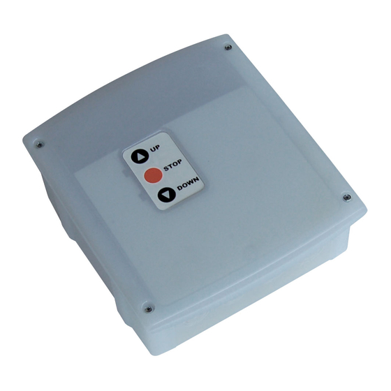
Page 7: Control Panel
CONTROL PANEL PROGRAMMING When power is on, the control unit checks that display correctly The functions of and times of the control unit are programmed 8.8.8.8 operates by switching on all segments for 1.5 sec. via the configuration menu, which can be accessed and explored Pr 1.0 Firmware version, e.g. - Page 8 INPUTS dEF1 dEF2 dEF3 dEF4 DISPLAY in 1 PHOTOCELL ACTIVE ONLY DURING PHOTOCELL ACTIVE DURING OPENING AND CLOSING CLOSING The intervention of the photocell during The intervention of the photocell during the the opening stage is ignored. opening phase causes the motor to stop. The intervention of the photocell during When the photocell beam is released, the the closing stage causes the shutter to...
- Page 9 OUTPUTS dEF1 dEF2 dEF3 dEF4 DISPLAY ou 1 FLASHING LIGHT COURTESY LIGHT Output (E1 - E2) is on intermittently The output (E1 - E2) is on and fixed during (2 Hz) during opening and closing opening, pause and closure. Having completed and during pause mode, if automatic the operating cycle, the light remains on for the reclosing is active...
- Page 10 OPERATING LOGIC dEF1 dEF2 dEF3 dEF4 DISPLAY Lo 5 TIMER FUNCTION EMERGENCY DEAD-MAN FUNCTION Each time the timer closes the contact If a command is rejected due to an active safety L1-L3, the automation starts during switch, you can activate the man mode on the opening and remains paused until the emergency switch (page 15) to move the shutter.
- Page 11 DISABLING OF THE SAFETY EDGE WHILE CLOSING Procedure for setting the edge disabling point 1. Enter the programming mode by holding the MENU key and selecting the item using the key 2. Set the parameter to 3. Make any other necessary settings and then exit the programming mode.
Need help?
Do you have a question about the EASY-LUX and is the answer not in the manual?
Questions and answers