Table of Contents
Advertisement
Quick Links
SINUMERIK
SINUMERIK 840D sl
TCU 30.3
Manual
Valid for: 6FC5312-0DA00-1AA1
Replaces the following products:
TCU.1: 6FC5312-0DA00-0AA0 and
6FC5312-0DA00-0AA1
TCU20.2: 6FC5312-0DA00-0AA2
TCU30.2: 6FC5312-0DA00-1AA0
09/2017
A5E40874197
Fundamental safety
instructions
Description
Mounting
Connection
Networking
Service and maintenance
Technical data
Spare parts / accessories
Safety symbols
1
2
3
4
5
6
7
8
9
Advertisement
Table of Contents

Related Manuals for Siemens SINUMERIK 840D sl TCU 30.3


Summary of Contents for Siemens SINUMERIK 840D sl TCU 30.3
- Page 1 Fundamental safety instructions Description Mounting SINUMERIK Connection SINUMERIK 840D sl TCU 30.3 Networking Service and maintenance Manual Technical data Spare parts / accessories Safety symbols Valid for: 6FC5312-0DA00-1AA1 Replaces the following products: TCU.1: 6FC5312-0DA00-0AA0 and 6FC5312-0DA00-0AA1 TCU20.2: 6FC5312-0DA00-0AA2 TCU30.2: 6FC5312-0DA00-1AA0 09/2017 A5E40874197...
- Page 2 Note the following: WARNING Siemens products may only be used for the applications described in the catalog and in the relevant technical documentation. If products and components from other manufacturers are used, these must be recommended or approved by Siemens. Proper transport, storage, installation, assembly, commissioning, operation and maintenance are required to ensure that the products operate safely and without any problems.
-
Page 3: Table Of Contents
Table of contents Fundamental safety instructions........................5 General safety instructions.......................5 Equipment damage due to electric fields or electrostatic discharge........8 Warranty and liability for application examples................8 Industrial security........................9 Residual risks of power drive systems...................10 Description..............................11 Overview..........................11 Configurations........................12 Interfaces..........................13 Rating plate..........................17 Mounting..............................19 Introduction..........................19 Mounting the TCU on the operator panel front with mounting bracket........19 Mounting the TCU on the operator panel front without mounting bracket......23 Connection..............................25... - Page 4 Table of contents 5.3.2 Networks without connection to the company network............46 5.3.2.1 Configuration 1: NCU and TCU....................46 5.3.3 Networks with NCU connection to the company network............47 5.3.3.1 Configuration 2: NCU and TCU....................47 5.3.3.2 Configuration 3: PCU with TCU on NCU................48 5.3.3.3 Connecting the programming device (PG) to the NCU............49 5.3.4...
-
Page 5: Fundamental Safety Instructions
Fundamental safety instructions General safety instructions WARNING Electric shock and danger to life due to other energy sources Touching live components can result in death or severe injury. ● Only work on electrical devices when you are qualified for this job. ●... -
Page 6: Technical Data
Fundamental safety instructions 1.1 General safety instructions WARNING Electric shock due to equipment damage Improper handling may cause damage to equipment. For damaged devices, hazardous voltages can be present at the enclosure or at exposed components; if touched, this can result in death or severe injury. - Page 7 ● If you come closer than around 2 m to such components, switch off any radios or mobile phones. ● Use the "SIEMENS Industry Online Support App" only on equipment that has already been switched off. WARNING...
-
Page 8: Equipment Damage Due To Electric Fields Or Electrostatic Discharge
Fundamental safety instructions 1.2 Equipment damage due to electric fields or electrostatic discharge Equipment damage due to electric fields or electrostatic discharge Electrostatic sensitive devices (ESD) are individual components, integrated circuits, modules or devices that may be damaged by either electric fields or electrostatic discharge. NOTICE Equipment damage due to electric fields or electrostatic discharge Electric fields or electrostatic discharge can cause malfunctions through damaged individual... -
Page 9: Industrial Security
Siemens’ products and solutions undergo continuous development to make them more secure. Siemens strongly recommends to apply product updates as soon as available and to always use the latest product versions. Use of product versions that are no longer supported, and failure to apply latest updates may increase customer’s exposure to cyber threats. -
Page 10: Residual Risks Of Power Drive Systems
Fundamental safety instructions 1.5 Residual risks of power drive systems Residual risks of power drive systems When assessing the machine- or system-related risk in accordance with the respective local regulations (e.g., EC Machinery Directive), the machine manufacturer or system installer must take into account the following residual risks emanating from the control and drive components of a drive system: 1. -
Page 11: Description
Description Overview A Thin Client Unit (TCU) allows the spatial separation between an operator panel (OP) / touch panel (TP) and the Panel Control Unit (PCU) / Numerical Control Unit (NCU). For this reason, the user interface is copied to one/several operator panel fronts, each with a TCU. Validity The description applies to the following TCU: Designation... -
Page 12: Configurations
This product contains open source software. License information can be obtained via the shortcut "License files" on your SINUMERIK PCU desktop, or navigate to the SINUMERIK Operate Readme OSS path "Setup/system data: System CF card/siemens/oss-license" on your SINUMERIK NCU and read the appropriate OSS file for this device. -
Page 13: Interfaces
Description 2.3 Interfaces Figure 2-2 Maximum configuration, several TCUs connected to an NCU 7x0 For information about TCU commissioning, see the section titled "Networking". Interfaces Overview Function Designation Description Double USB interface 1 X203 / X204 2 x USB 2.0 Hi-Speed type A Double USB interface 2 X212 / X213 2 x USB 2.0 Hi-Speed type A... - Page 14 Description 2.3 Interfaces Function Designation Description LVDS display interface K3 X209 2 x 10-pin plug connector Ethernet interface X202 8-pin RJ45 socket One of the interfaces can be loaded with 500 mA, the other with 100 mA. To connect to a 10" to 15" operator panel front To connect to an OP 019 operator panel front The following special requirements apply to the connecting cables: ●...
- Page 15 Description 2.3 Interfaces View ① X203/X204 Double USB interface 1 ② X212/X213 Double USB interface 2 ③ X202 Ethernet interface ④ X205 Interface for direct keys ⑤ X206 24 VDC power supply ⑥ Protective conductor connection Figure 2-3 Front view of the TCU 30.3 with interfaces TCU 30.3 Manual, 09/2017, A5E40874197...
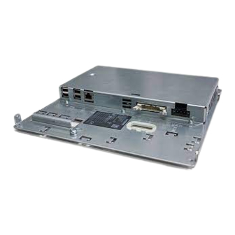
- Page 16 Description 2.3 Interfaces ⑦ X207 I/O USB interface K1 ⑧ X208 LVDS display interface K2 ⑨ X209 LVDS display interface K3 (not for TCU 20.2) Figure 2-4 Rear view of the TCU 30.3 with interfaces The K1, K2, K3 interfaces are suitable only for connecting operator panel fronts OP 010, OP 010S, OP 010C, OP 012, OP 015, OP 015A, TP 015A and OP 019.
-
Page 17: Rating Plate
The product code contains the article number of the device. Scan the product code with the aid of the Siemens Industry Online Support App to be taken directly to the Internet Webpage for the product, including all of the technical information and graphical data. - Page 18 Description 2.4 Rating plate TCU 30.3 Manual, 09/2017, A5E40874197...
-
Page 19: Mounting
Mounting Introduction Before assembling the two components, the interface cables of the operator panel front (IO/ USB cable K1, K2 display cable and, if necessary, K3) must be inserted into the corresponding socket of the TCU (visible behind the housing cut-out). Note Since some of the interfaces do not have a cable strain relief for the cables to be connected, it is recommended to secure the cables to the u-shaped lugs on the supporting plate using... - Page 20 Mounting 3.2 Mounting the TCU on the operator panel front with mounting bracket OP 010, OP 010S, OP 010C, OP 012, OP 015, OP 015A, TP 015A and OP 019 Two mounting brackets (must be ordered separately) are required for mounting these operator panel fronts (see Section "Accessories (Page 83)").
- Page 21 Mounting 3.2 Mounting the TCU on the operator panel front with mounting bracket 3. Insert cables K1, K2 and K3 (only for OP 019). 4. Close the cabled TCU mounting bracket unit and attach it using the four knurled screws ②...
- Page 22 Mounting 3.2 Mounting the TCU on the operator panel front with mounting bracket NOTICE Impermissible mounting positions can cause malfunctions Observe the permissible mounting position: Deviating by up to 5º from the vertical. Only the shown mounting position is permitted. TCU 30.3 Manual, 09/2017, A5E40874197...
-
Page 23: Mounting The Tcu On The Operator Panel Front Without Mounting Bracket
Mounting 3.3 Mounting the TCU on the operator panel front without mounting bracket Mounting the TCU on the operator panel front without mounting bracket The OP 010S operator panel front and the TCU can be screwed together without any additional mounting brackets. - Page 24 Mounting 3.3 Mounting the TCU on the operator panel front without mounting bracket NOTICE Impermissible mounting positions can cause malfunctions Observe the permissible mounting position: Deviating by up to 5º from the vertical. TCU 30.3 Manual, 09/2017, A5E40874197...
-
Page 25: Connection
Connection Pin assignment of the interfaces The pins of the component interfaces are assigned as specified in the tables below. Any deviations are indicated at the relevant point. Signal type Input Output Bidirectional (inputs/outputs) Power supply Ground (reference potential) or N.C. (not connected) 4.1.1 Power supply Connector type:... - Page 26 Connection 4.1 Pin assignment of the interfaces In principle, USB interfaces have the following characteristics: ● Integrated power supply up to 500 mA for each socket. ● Maximum cable length 3 m (Length including the supply cable to the hub and the connected terminal device;...
-
Page 27: Ethernet Rj45 Interface
Connection 4.1 Pin assignment of the interfaces 4.1.3 Ethernet RJ45 interface Connector type: Standard RJ45 socket Max. data transmission rate: 10/100/1000 Mbit/s Max. cable length: 100 m Table 4-3 Assignment of the Ethernet RJ45 interface 10/100 Mbit/s Connector Name Type Remark TxD+ Transmit data... -
Page 28: Lvds Display Interface
Connection 4.1 Pin assignment of the interfaces 4.1.4 LVDS display interface LVDS display interface channel 1 Used to connect operator panel fronts with TFT displays with 640 x 480 pixels (VGA), 800 x 600 pixels (SVGA) or 1024 x 768 pixels (XGA). Associated interface cable: K2, max. -
Page 29: Direct Key Interface
Connection 4.1 Pin assignment of the interfaces Table 4-6 Allocation of the LVDS display interface Connector Name Type Meaning System ground (reference potential) RXIN10- LVDS input signal Bit 0 (-) RXIN10+ Bit 0 (+) System ground (reference potential) RXIN1- LVDS input signal Bit 1 (-) RXIN1+ Bit 1 (+) - Page 30 Connection 4.1 Pin assignment of the interfaces Figure 4-1 Assignment of the direct keys to the vertical softkeys of an operator panel front 16 digital inputs (5 V) can be fetched via the X11 connector. Connector designation: Connector type: 20-pin plug connector Max.
- Page 31 Connection 4.1 Pin assignment of the interfaces Table 4-8 Assignment of connector X70 (MCP, MPP, HAM) / X205 (TCU) / DTM Name Type Meaning Direct key 1 DT16 Direct key 16 P5V / CON1 + 5 V input voltage P5V / CON2 + 5 V input voltage Ground Ground...
- Page 32 Connection 4.1 Pin assignment of the interfaces TCU 30.3 Manual, 09/2017, A5E40874197...
-
Page 33: Networking
Networking System settings 5.1.1 Thin Client Unit (TCU) TCU overview The Thin Client Unit (TCU) for the distributed configuration permits spatial separation of the SINUMERIK operator panel front (OP/TP) and the SINUMERIK PCU or NCU. On the SINUMERIK solution line, the TCU is used to display the user interface of the PCU 50 or the NCU. -
Page 34: Settings For Sinumerik Solution Line
Networking 5.1 System settings Supplementary conditions For operation of a TCU: ● In the system network, the number of active TCUs is limited: – a maximum of 2 TCUs: NCU 710.3 PN – a maximum of 4 TCUs: NCU 720.3 PN or NCU 730.3 PN –... - Page 35 Networking 5.1 System settings The following rules apply for assignment of IP addresses in the system network: ● For all NCUs and PCUs, the commissioning engineer assigns fixed IP addresses in the associated address bands, as well as appropriate computer names (host names). All other (operator) components are automatically assigned an IP address from the DHCP server.
-
Page 36: System Boot With System Network
Networking 5.1 System settings 5.1.3 System boot with system network System behavior at boot The system boot behavior is based on the following principle: ● For configuration of an NCU 7x0 with a PU 50, the default for a network configuration is as follows: The NCU keeps the default IP address 192.168.214.1 on X120, the PCU 50 keeps the default IP address 192.168.214.241 on Eth2. -
Page 37: Factory Default Settings
Networking 5.1 System settings 5.1.4 Factory default settings Meaning of the symbols: ○ Eth 1 as a DHCP client ● Eth 2 as a DHCP server ■ Eth 2 with a fixed IP address Preconfiguration of the TCU The TCU is configured as a DHCP client and primarily accepts IP addresses from SINUMERIK components, from the DHCP server of such components that are inherent to SINUMERIK, for example, an NCU at X120 or a PCU on the system network or from a default DHCP server. - Page 38 Networking 5.1 System settings The NCU has three Ethernet connections: - X120 to connect to the system network with an active DHCP serv‐ er (Eth 0) - X130 to connect to the company network as a default DHCP client (Eth 1) - X127 as a service connection with an active DHCP server (Ibn 0) On X130, the NCU is set as a default DHCP client for the address reference from a company network.
-
Page 39: Commissioning Tcu
Networking 5.2 Commissioning TCU Commissioning TCU 5.2.1 Key assignment Key assignment Functions of the keys and softkeys in the "Operator panel service system": Softkey Key on OP External key‐ Description board HSK1 <F1> Moves the cursor down a row HSK2 <F2>... -
Page 40: Settings In The "Tcu.ini" File
Networking 5.2 Commissioning TCU 5.2.2 Settings in the "TCU.ini" file Directories The tcu.ini file is created in the following directories: NCU: ../siemens/system/etc/tcu.ini ../user/system/etc/tcu.ini ../oem/system/etc/tcu.ini PCU (Windows 7): C:\ProgramData\Siemens\MotionControl\siemens\System\etc\tcu.ini C:\ProgramData\Siemens\MotionControl\user\System\etc\tcu.ini C:\ProgramData\Siemens\MotionControl\oem\System\etc\tcu.ini Note The following entries are evaluated by SINUMERIK Operate: ● VNCServer/VetoMode ●... -
Page 41: Displacement Mechanism For Tcus
Networking 5.2 Commissioning TCU ExternalTcuIP_1= You can also set the screen resolution that you want in the tcu.ini file: [VNCServer] Resolution = ... 5.2.3 Displacement mechanism for TCUs Supplementary conditions The following supplementary conditions apply when operating the TCU: 2 active TCU connected in parallel to NCU 710.3 PN 4 active TCU connected in parallel to NCU 720.3 PN, NCU 730.3 PN 4 active TCU connected in parallel to PCU To operate a machine with more operating stations then the maximum number the... -
Page 42: Disable Switchover Between Tcu Via Plc
Networking 5.2 Commissioning TCU 5.2.4 Disable switchover between TCU via PLC Overview The TCU switchover disable offers the option of dynamically disabling switchover from one TCU to the next when the system is running via the PLC. For the duration of the disable, a user authorization request to change user authorizations between TCUs will be ignored by the system and rejected. - Page 43 Networking 5.2 Commissioning TCU Operating principle If the TCU_SHIFT_LOCK bit is set for switchover disable, a user authorization request is not carried out independently of the mode set on the HMI for allocation of user authorizations (veto mode), i.e., a change of user authorization is rejected. This message appears on all OPs for approximately 5 seconds: "No switchover: Switchover disable set in current PLC."...
-
Page 44: Example: How To Select The Behavior Of The Tcus During Boot Up
Networking 5.2 Commissioning TCU Obtaining user authorization On a TCU that has no user authorization, the first key that is pressed serves exclusively to request the user authorization, i.e. this key is not evaluated by the operating software. The settings for the right to veto are stored in file tcu.ini and are only effective if the operating software is installed on the PCU. -
Page 45: Network Configuration
Networking 5.3 Network configuration Network configuration 5.3.1 Permissible network topologies Ethernet connection A SINUMERIK 840 D sl can only be operated as a network within which the individual components communicate with one another via Ethernet connections. This network must be set up. -
Page 46: Networks Without Connection To The Company Network
Networking 5.3 Network configuration 5.3.2 Networks without connection to the company network 5.3.2.1 Configuration 1: NCU and TCU Description A direct Ethernet connection is used to connect a TCU to X120 of the NCU. NCU and TCU are suitably preconfigured with IP addresses. The IP addresses are not significant for further operation. -
Page 47: Networks With Ncu Connection To The Company Network
Networking 5.3 Network configuration 5.3.3 Networks with NCU connection to the company network 5.3.3.1 Configuration 2: NCU and TCU Description The TCU is connected to the NCU (directly) using a crossed Ethernet cable. On X130, the NCU is connected to a switch to the company network with a straight cable. As in configuration 1, there is a direct Ethernet connection between a TCU and X120 of the NCU. -
Page 48: Configuration 3: Pcu With Tcu On Ncu
Networking 5.3 Network configuration If the company network offers a low level of administration (in the worst case scenario the network has only one DHCP server that assigns the addresses from a predefined address range) the NCU receives an IP address that is initially unknown. 5.3.3.2 Configuration 3: PCU with TCU on NCU Description... -
Page 49: Connecting The Programming Device (Pg) To The Ncu
Networking 5.3 Network configuration 5.3.3.3 Connecting the programming device (PG) to the NCU Description For service purposes a programming device is connected to the NCU at X127 as a standard DHCP client (automatically obtain an IP address). An NCU is a standard DHCP server on X127. - Page 50 Figure 5-1 Configuration example Configuration The config.ini file is located in the following directory: NCU: /user/common/tcu/<TCU name>/common/tcu PCU (Windows 7): C:\ProgramData\Siemens\MotionControl\user\common\tcu\<TCU name> \common\tcu The config.ini file must be stored on the boot server (active DHCP). TCU 30.3 Manual, 09/2017, A5E40874197...
-
Page 51: Service And Diagnostics
Networking 5.4 Service and diagnostics Example: [Station] maxhostindex=2 /* Number of nodes that are defined under [host_1] and [host_2]. mcpIndex=192 tcuIndex=1 eksIndex=0 [host_1] Address=192.168.214.1 /* Address of the NCU to which the connection is established during booting. [host_2] Address=157.163.230.202 /* Address of the PC password=123456 /* Password of the VNC server on the PC Switching over between the nodes... - Page 52 Networking 5.4 Service and diagnostics ① "Main menu" title followed by the TCU name in brackets ② Central area with the list of servers and two further permanent items, "Select service session" and "Service this panel": ● "Select service session" triggers a server scan which detects all the VNC servers in the local (system) network.
-
Page 53: Operating The Tcu Menu "Service Sessions
Networking 5.4 Service and diagnostics "Details" softkey The following connection data for the selected device appears when the "Details" softkey is pressed: Figure 5-3 TCU menu: Connection data 5.4.2 Operating the TCU menu "Service sessions" "Service sessions" dialog When "Select service session" is selected from the main menu, the resulting process begins by triggering a server scan: TCU 30.3 Manual, 09/2017, A5E40874197... - Page 54 Networking 5.4 Service and diagnostics Figure 5-4 TCU menu: Scanning After this, the following dialog appears: TCU 30.3 Manual, 09/2017, A5E40874197...
- Page 55 Networking 5.4 Service and diagnostics Figure 5-5 TCU menu: Active sessions Central area with the server list: The individual server lines contain either "Show WHAT on NAME (IP)" or the IP address only where the name is unknown. Session number VNC server Session 0 Session 4...
-
Page 56: Operating The Tcu Menu "Service Menu
Networking 5.4 Service and diagnostics precise details on the reason for the loss of function. With more favorable scenarios, the session name for the VNC server will also be specified along with its resolution. The connection and HMI status are monitored on a regular basis in the background. This may mean that these details change spontaneously if a change is made on the relevant server (for example, it may be switched off, the HMI may become available, etc.). - Page 57 Networking 5.4 Service and diagnostics The following menu items are available here: ● "Show status" shows status information, for example: Software version, hardware information, TCU network data, and their configuration: Figure 5-7 TCU menu: OP status ● "Show local logfile" shows a filtered version of the system log file in directory /var/log/ messages , which contains only the messages of the local TCUs.
- Page 58 Networking 5.4 Service and diagnostics Figure 5-8 TCU menu: Local log file ● "Show logfile of remote devices" shows the log file of the other devices in the network: The syslog messages of devices in the system network which send syslog messages by broadcast, such as NCU 7x0, ...
-
Page 59: Operating The Tcu Menu "Modify Settings
Networking 5.4 Service and diagnostics 5.4.4 Operating the TCU menu "Modify settings" "Modify settings for operator panel (TCU)" dialog The following dialog appears when "Modify settings" is selected from the main menu: Figure 5-9 TCU menu: Settings In this dialog, you set the TCU parameters during first commissioning: ●... -
Page 60: Operating The Menu For A New Tcu Or Spare Part Tcu
Networking 5.4 Service and diagnostics ● "Electronic key system index - EKS" (0-255) Specifies the index of the associated EKS; see column "EKS" on the user interface. ● "Enable direct keys" (yes/no) Specifies whether direct keys are registered with the PLC (yes) or are treated as ordinary keys (no);... - Page 61 Networking 5.4 Service and diagnostics Figure 5-10 TCU menu: New TCU If all TCUs are active, the new TCU cannot be a spare part and, after a certain time interval, the field for entering a name will automatically appear. TCU 30.3 Manual, 09/2017, A5E40874197...
- Page 62 Networking 5.4 Service and diagnostics Figure 5-11 TCU menu: Name of TCU If a TCU30.3 is to be operated with a software version before 4.7 SP2, the TCU is operated in compatibility mode. If required, you can view and change the emulation type in the settings. Replacing a device If "Replacement"...
- Page 63 Networking 5.4 Service and diagnostics Figure 5-12 TCU menu: Replacement TCU With the TCU30.3 and TCU30.3 legacy, after selecting the TCU to be replaced, a further dialog to select the emulation type can be displayed in compatibility mode: TCU 30.3 Manual, 09/2017, A5E40874197...
- Page 64 Networking 5.4 Service and diagnostics If a static.ini of the TCU to be replaced (as of SW4.5) is found on the server, then the type of the old TCU is preselected based on the HW ID found there. If this is not the case, the TCU20.2 type is selected.
-
Page 65: How To Register A Tcu On The System Network
Networking 5.4 Service and diagnostics Assigning a name If, as described above, the system automatically follows the "New" path, an additional message will appear: "This operator panel (TCU) must be new, because there are no inactive panels." This message will not appear if "New" is selected manually. Figure 5-13 TCU menu: Name of TCU An available TCU name is suggested in the input field, although the user is able to change... - Page 66 Networking 5.4 Service and diagnostics Sequence for a TCU Procedure: 1. Connect TCU. This opens the "New operator panel (TCU)" dialog. 2. Select "New" to connect a new TCU and "OK" to confirm. 3. In the next dialog, accept the name suggested by the system or enter a name and confirm this with "OK".
- Page 67 Networking 5.4 Service and diagnostics Sequence for the HT 8 Procedure: 1. Connect HT 8 to a connection module and calibrate the touch screen. Additional softkeys are available for convenient touch panel operation: – "OK" has the same effect as the <INPUT> key –...
-
Page 68: This Is How You Register A Spare Part Tcu
Networking 5.4 Service and diagnostics Specifying settings without machine control panel If a PCU or a TCU has no machine control panel (MCP), you must set one of the two following options: ● MCP address = 0 or no entry After the change of user authorization, there is no switchover of the machine control panel;... -
Page 69: Booting Of The Tcu
Networking 5.4 Service and diagnostics 5.4.8 Booting of the TCU 5.4.8.1 Messages during booting Messages when booting While the TCU is booting, progress is displayed after the BIOS has been loaded and before the operating system is started. In addition to messages, the current booting status is also indicated by a progress bar. -
Page 70: Diagnostics Options During Booting
Networking 5.4 Service and diagnostics 5.4.8.2 Diagnostics options during booting Diagnostics options during booting In the following cases, the diagnostics window is displayed and booting of the TCU is interrupted: ● When the <1 / F1> function is selected during booting ●... - Page 71 Networking 5.4 Service and diagnostics Press <1 / F1> to continue If you select function <F1> in the diagnostics window, the, detailed diagnostic information is output. Key / text Meaning F1 ... F6 Navigate within the window (alternatively, the relevant keys on the OP can be used). F7 -detail Display less information F8 +detail...
- Page 72 Networking 5.4 Service and diagnostics TCU 30.3 Manual, 09/2017, A5E40874197...
-
Page 73: Service And Maintenance
Service and maintenance Cleaning the device The TCU is designed for low-maintenance operation. Preparation Note Clean the TCU only when it is switched off. For cleaning, use a soft cloth moistened either with water or a mild cleaning agent. Use only dish soap as cleaning agent. - Page 74 Service and maintenance Signs for a suspected malfunction: ● Unusual or no functioning ● Unusual heat generation ● Smoke development Repair Send the TCU back to the manufacturer for repair. The TCU may be repaired only there. TCU 30.3 Manual, 09/2017, A5E40874197...
-
Page 75: Technical Data
Technical data Technical data Safety Safety class Degree of protection accord‐ IP00 (open equipment) ing to EN 60529 IP20 (mounted, end application minimum requirement) Approvals CE / cULus Flame resistance UL 94 V-1 Electrical data Overvoltage category Secondary circuit supplied from primary circuits up to Cat. III, 300 VAC Power supply 24 VDC (20.4 V ... -
Page 76: Supplementary Electrical Conditions
Technical data 7.2 Supplementary electrical conditions Supplementary electrical conditions 7.2.1 Power supply Requirements for DC power supplies WARNING Electric shock due to connection of an unsuitable power supply When equipment is connected to an unsuitable power supply and/or insufficiently grounded (Page 19), exposed components may carry a hazardous voltage that might result in serious injury or death. -
Page 77: Grounding Concept
Technical data 7.2 Supplementary electrical conditions 7.2.2 Grounding concept Components The SINUMERIK 840D sl system consists of a number of individual components which have been designed so that the system complies with the appropriate EMC and safety standards. The individual system components are: ●... -
Page 78: Sinumerik_Southkorea_Note
90°), but must never be laid close or parallel to one another. ● Only use cables approved by SIEMENS for the signal lines from and to the Control Unit. ● Signal cables must not be routed close to strong external magnetic fields (e.g. motors and transformers). -
Page 79: Climatic And Mechanical Environmental Conditions
Technical data 7.3 Climatic and mechanical environmental conditions maintained. Further, additional measures may be required, for instance, using an additional radio interference suppression filter (EMC filter). The measures for EMC-compliant design of the system are described in detail in this manual respectively in the Installation Guideline EMC. -
Page 80: Operating Conditions
Technical data 7.3 Climatic and mechanical environmental conditions Type of condition Permissible range/class Water other than rain 1 m/s and wet loading surfa‐ Not permis‐ 1 m/s and wet sible loading surfaces Height Max. 4,000 m above sea level Condensation, splash water, Permissible Not permis‐... - Page 81 Technical data 7.3 Climatic and mechanical environmental conditions Climatic environmental conditions Installation altitude Up to 1000 m without derating From 1000 m to 4000 m with linear ambient temperature de‐ rating, -0.5 K per 100 m Relative humidity 5 ... 95% (no condensation) Oil mist, salt mist, ice formation, con‐...
-
Page 82: Standards And Approvals
Technical data 7.4 Standards and approvals Standards and approvals Approvals CE approval Figure 7-1 CE marking The operator panels and the safety-relevant accessories satisfy the requirements and protection objectives of the following EC directives. The operator panels and the safety- relevant accessories comply with the harmonized European standards (EN), promulgated in the Official Journals of the European Community: ●... -
Page 83: Spare Parts / Accessories
Spare parts / accessories Accessories Table 8-1 Accessories for the TCU Component Description Quantity Article number Mounting bracket Mounting bracket for PCU, video link re‐ 1 set 6FC5248-0AF20-2AA0 ceiver or TCU behind operator panel front (2 items) Direct key cable Ribbon cable for connection of the direct 6FC5347-0AF10-0AA0 key interfaces for OP and TCU. - Page 84 Spare parts / accessories 8.2 Handling membrane connectors Clamping frame of socket Figure 8-1 Removing (left) and attaching (right) a membrane connector Unplugging the membrane connector 1. Loosen the dark clamping frame of the socket by pushing it up with your fingernails until it engages in its upper, unlocked position (Fig.
-
Page 85: Safety Symbols
Safety symbols Icon Explanation The equipment is only suitable for direct current. Used for marking cor‐ responding terminals. Direct current For marking the connection for an external protective conductor for pro‐ tecting against electrical shock in the event of an error or for a connect‐ ing terminal of the external protective conductor. - Page 86 Safety symbols TCU 30.3 Manual, 09/2017, A5E40874197...
-
Page 87: Index
Index Boot server, 48 HT 8 rotary coding switch, 67 Care, 73 Maintenance, 73 Cleaning agent, 73 Membrane connectors CompactFlash Card, 34 Connection conditions, 83 Company network, 35 Messages during TCU boot up, 69 Configurations Mounting bracket TCU 30.3, 12 Thin Client Unit, 20, 83 Connecting a PG, 49 Connection conditions... - Page 88 Index Main menu, 51 Settings, 65 Supplementary conditions, 34 Thin Client Unit, 33 TCU 30.3 Configurations, 12 TCU diagnostics, 69 Thin Client Unit DHCP server, 12 Dimensions, 75 Ethernet cable, 83 Ethernet, Industrial, 11 Mounting bracket, 20, 83 User authorization, 33, 44 TCU 30.3 Manual, 09/2017, A5E40874197...
Need help?
Do you have a question about the SINUMERIK 840D sl TCU 30.3 and is the answer not in the manual?
Questions and answers