
Subscribe to Our Youtube Channel
Related Manuals for Siemens OOH740


Summary of Contents for Siemens OOH740
- Page 1 OOH740, OOHC740 Automatic fire detectors Technical Manual Building Technologies A6V10305793_k_en_-- 2013-04-04 Control Products and Systems...
-
Page 2: Legal Notice
Legal notice Technical specifications and availability subject to change without notice. © 2010-2013 Copyright by Siemens Switzerland Ltd Transmittal, reproduction, dissemination and/or editing of this document as well as utilization of its contents and communication thereof to others without express authorization are prohibited. -
Page 3: Table Of Contents
Standards and directives complied with ............14 Release Notes ....................14 Structure and function ................. 15 Overview ......................15 3.1.1 Multi-sensor smoke detector, ASA OOH740 ........16 3.1.2 Neural fire detector OOHC740 ............17 3.1.3 Features of fire detection functionality ..........18 3.1.4... - Page 4 4.2.6 Default settings for operating on the C-NET ........49 4.2.7 Setting a parameter set in collective operation ......... 50 4.2.8 Sample applications for OOH740 ............. 50 4.2.9 Sample applications for OOHC740........... 51 Technical CO alarm ..................51 4.3.1 Ambient features................52 4.3.2...
- Page 5 Testing the functionality of the 'Technical Ambient Supervision Alarm' ................77 7.2.4.1 'Technical Ambient Supervision Alarm' performance check ....78 Specifications ....................79 Technical data for OOH740 ................79 Technical data for OOHC740 ................82 Dimensions ....................84 Environmental compatibility ................84 Index......................85...
- Page 6 About this document Technical terms Building Technologies A6V10305793_k_en_-- Fire Safety 2013-04-04...
-
Page 7: About This Document
Technical terms 1 About this document Goal and purpose This document contains all the information you'll need on automatic fire detectors OOH740 OOHC740 Following the instructions consistently will ensure that the product can be used safely and without any problems. -
Page 8: Document Identification
About this document Technical terms Document identification The document ID is structured as follows: ID code Examples ID_ModificationIndex_Language_COUNTRY A6V10215123_a_de_DE -- = multilingual or international A6V10215123_a_en_-- A6V10315123_a_--_-- Conventions for text marking Markups Special markups are shown in this document as follows: Requirement for a behavior instruction Intermediate result of a behavior instruction End result of a behavior instruction... -
Page 9: Applicable Documents
LPCB approval; date format changed in accordance with specifications of ISO 8601 (format: yyyy-mm-dd) 02.2012 Detector base DB722 and base attachment BA720 added, marine approval for OOH740 added 11.2011 OOH740: VdS approval and CPD number added 09.2011 IP protection categories adapted 06.2011 Chapter 'Removing the diode unit' added 05.2011 Detector base DB110 added 02.2011... - Page 10 About this document History of changes The language versions and country variants produced by a local company have the same modification index as the corresponding reference document. They are not however included in the table below. The table below shows the published language versions with the corresponding modification index: Modification index en_--...
-
Page 11: Safety
Safety Safety instructions 2 Safety 2.1 Safety instructions The safety notices must be observed in order to protect people and property. The safety notices in this document contain the following elements: Symbol for danger Signal word Nature and origin of the danger Consequences if the danger occurs Measures or prohibitions for danger avoidance Symbol for danger... -
Page 12: Safety Regulations For The Method Of Operation
2.2 Safety regulations for the method of operation National standards, regulations and legislation Siemens products are developed and produced in compliance with the relevant European and international safety standards. Should additional national or local safety standards or legislation concerning the planning, assembly, installation,... - Page 13 Modifications to the system and to individual products may lead to faults, malfunctioning and safety risks. Written confirmation must be obtained from Siemens and the corresponding safety bodies for modifications or additions. Modules and spare parts Components and spare parts must comply with the technical specifications defined by Siemens.
-
Page 14: Standards And Directives Complied With
Personal injury or damage to property caused by poor maintenance or lack of maintenance 2.3 Standards and directives complied with A list of the standards and directives complied with is available from your Siemens contact. 2.4 Release Notes Limitations to the configuration or use of devices in a fire detection installation with a particular firmware version are possible. -
Page 15: Structure And Function
3 Structure and function 3.1 Overview In this document the following point detectors are referred to collectively using the term 'automatic fire detectors': Multi-sensor smoke detector, ASA OOH740 Neural fire detector OOHC740 Multi-sensor smoke detector, ASA Neural fire detector OOH740... -
Page 16: Multi-Sensor Smoke Detector, Asa Ooh740
Structure and function Overview 3.1.1 Multi-sensor smoke detector, ASA OOH740 Multi-sensor smoke detector, ASA OOH740 Properties Communication via C-NET (addressed detector line) Address automatically issued during commissioning Can also be used on collective detector lines in conjunction with the detector... -
Page 17: Neural Fire Detector Oohc740
Structure and function Overview 3.1.2 Neural fire detector OOHC740 Neural fire detector OOHC740 Properties Communication via C-NET (addressed detector line) Address automatically issued during commissioning Built-in line separator Signal processing with ASAtechnology and optional detection behavior (application-specific ASA parameter sets) Software can be used to set as: –... -
Page 18: Features Of Fire Detection Functionality
Structure and function Overview 3.1.3 Features of fire detection functionality Properties Dynamic influence on the parameter sets Pattern recognition Real time interpretation of the situation Process- and time-controlled switchover of the parameter sets The point detectors' signal processing is based on ASAtechnology (ASA = Advanced Signal Analysis). -
Page 19: Features Of The 'Technical Co Alarm
Structure and function Overview Switching over the parameter set In addition to selecting the parameter set, the point detectors with ASAtechnology enable time- or process-controlled switching over of the parameter sets (Manned/Unmanned switchover). Thanks to this function, the detector can be used in places where the situation changes regularly and frequently (e.g. - Page 20 Structure and function Overview Sensory The signals captured by the CO sensor are corrected with regard to CO exposure, sensor sensitivity, temperature and aging and supplied to the algorithm. The algorithms are set by selecting the parameter set. Algorithms The parameter set can be used to select static and dynamic algorithms. A real time interpretation of the ambient conditions results in improved measurement accuracy.
-
Page 21: Features Of The 'Technical Ambient Supervision Alarm
The signals for CO detection or temperature recording must not be used to control fire detection equipment in accordance with EN 54-2. 3.1.6 Details for ordering Type Order no. Designation OOH740 S54320-F7-A3 Multi-sensor smoke detector, ASA OOHC740 S54320-F8-A3 Neural fire detector Building Technologies... -
Page 22: Product Version Es
Structure and function Overview 3.1.7 Product version ES The product version ES provides the technical status of a device in terms of software and hardware. The product version is provided as a two-digit number. You will find the details of your device's product version: On the packaging label On the product label or the type plate Product version on the packaging label... -
Page 23: Setup
Structure and function Setup 3.2 Setup 3.2.1 Structure of OOH740 The multi-sensor smoke detector, ASA OOH740 is a multiple criteria fire detector and has two optical and two thermal sensors. Structure and function Sensors of the OOH740 1 Heat sensors... -
Page 24: Structure Of Oohc740
Structure and function Setup 3.2.2 Structure of OOHC740 The neural fire detector OOHC740 is a multiple criteria fire detector and has two optical sensors, two thermal sensors and one CO sensor. Structure and function Sensors of the OOHC740 1 Heat sensors 4 Forward scatterer 2 Receiver 5 Labyrinth... - Page 25 Structure and function Setup You can set the following response behaviors on the neural fire detector OOHC740: Combined optical and thermal Combined optical, thermal and CO Optical smoke detector alone Heat detector alone The response behavior is determined by selecting one of the following sensor modes: Sensor mode 0: Application as neural fire detector Sensor mode 1: Application as heat detector...
-
Page 26: Function
Structure and function Function Technical Ambient Supervision Alarm 'Technical Ambient Supervision Alarm' mode detects an increase in temperature or CO concentration above a specified trigger threshold caused by hysteresis. Temperature monitoring compares the current measured temperature with a preset threshold value. CO monitoring compares the current measured CO concentration with a preset threshold value. -
Page 27: Parameter Sets For Fire
Function Parameter sets for fire in collective mode The point detector OOH740 can also be operated in collective mode. There are several parameter sets for fire available in collective mode. The parameter sets are selected in collective mode using resistors installed in the detector base. - Page 28 Three times every 8 s (resistor PSR720-2) If there is still a flashing signal on a point detector OOH740 more than 3 minutes after the detector line was started up, there is a fault. More information can be found in the chapter Internal alarm indicator [ 32].
-
Page 29: Parameter Sets For 'Technical Co Alarm
The neural fire detector OOHC740 cannot be operated as a pure CO detector. You must always select a parameter set for fire as well as the parameter set for Overview of parameter sets for CO detection Parameter set OOH740 OOHC740 'Robust EU1' –... -
Page 30: Warning Levels For Co
The evaluation of the danger level and the decisions to be taken (e.g. activation of remote transmission) are configured in the fire detection system. Danger levels when operating on a collective detector line The point detector OOH740 can transmit the following danger levels to the fire control panel: Danger level... -
Page 31: Diagnosis Levels
The CO sensor can only be monitored for failure. For a functional test, the CO sensor must be tested with test gas. Operating the point detector OOH740 in collective mode: When an error occurs which impairs the correct functionality of the device, a fault message is reported to the control panel. -
Page 32: Line Separator
Flashing mode of alarm indicator Alarm AI flashes every second Locate AI flashes every second The following displays are possible when operating the point detector OOH740 in collective mode: Operating condition Flashing mode of alarm indicator Fault Two flashes every 4 s... -
Page 33: Connection For External Alarm Indicators
Operating the point detector OOH740 in collective mode: The external alarm indicator is activated in the event of an alarm. Two external alarm indicators can be connected to the point detector OOH740. See also Sounder base DBS720 [... -
Page 34: Test Mode
RE7T Solo461 heat detector tester kit The CO sensor can be tested with the test gas REF8-C. Operating the point detector OOH740 in collective mode: Once the point detector has been inserted into the detector base or once the detector line has been reset, the point detector is in test mode for a period of 3 minutes. -
Page 35: Line Tester
Structure and function Function In degraded mode operation, the OOHC740 only supports the 'Fire' alarm class. If the 'CO' alarm class is also be supported in degraded mode operation, technical customer support should be informed. Degraded mode operation on the C-NET is not supported in the same way by all control panels. -
Page 36: Mechanical Setup
Structure and function Mechanical setup 3.4 Mechanical setup One of the following devices is required to install a point detector: Detector base DB72x or detector base (collective) DB110 Sounder base DBS720 After installing the detector base or sounder base, simply insert the point detector in the base and turn it, either manually or using the detector exchanger DX791 and the adapter for detector exchanger FDUD491, until you hear and feel it snap in. -
Page 37: Accessories
Multi-sensor fire detector OH720 – Smoke detector OP720 – Heat detector HI720 – Heat detector HI722 – Multi-sensor smoke detector, ASA OOH740 – Neural fire detector OOHC740 – Interbase DBS72x Order no.: S54319-F11-A1 See also Detector base DB72x and detector base (collective) DB110 Cable entry [ 3.5.2... -
Page 38: Detector Base Db721D
For the recess-mounted cable entry For surface-mounted cable entry, up to 8 mm cable diameter Compatible with: – Multi-sensor smoke detector, ASA OOH740 Order no.: S54319-F15-A1 See also Detector base DB72x and detector base (collective) DB110 Cable entry [ 3.5.4... -
Page 39: Sounder Base Dbs720
– Smoke detector OP720 – Heat detector HI720 – Heat detector HI722 – Multi-sensor smoke detector, ASA OOH740 – Neural fire detector OOHC740 For details, please refer to document A6V10218037 Order no.: S54319-F5-A1 See also Sounder base DBS720 [ Cable entry [ 3.5.6... -
Page 40: Designation Plate Fdbz291
Multi-sensor fire detector OH720 – Smoke detector OP720 – Heat detector HI720 – Heat detector HI722 – Multi-sensor smoke detector, ASA OOH740 – Neural fire detector OOHC740 Order no.: S54319-F9-A1 See also Detector locking device LP720 [ 3.5.10 Micro terminal DBZ1190-AA Auxiliary terminal for connecting cables For T-branches of additional cabling e.g. -
Page 41: Resistors Psr720-1
Connection diagram, collective [ 3.5.13 Resistors PSR720-2 For selecting the 'High Sensitive Fast' parameter set on a point detector OOH740 in collective mode Resistance value: 68 k Install the resistors directly in a detector base DB721D or detector base (collective) DB110... -
Page 42: Planning
4 Planning 4.1 Compatibility Compatible with control panels that support the C-NET detector line. The point detector OOH740 is also compatible with control panels which support collective mode. You will find details in the 'List of compatibility'. The table below shows the compatibility of the devices with various product lines:... - Page 43 Planning Fire detection Room geometry High ceilings, complex room shapes or well ventilated rooms have a complex room geometry. This aggravates early fire detection, as it is difficult for the fire phenomenon to reach the fire detector. An office room with normal ceiling height has a simple room geometry.
-
Page 44: Parameter Sets: Sensor Mode 0 'Neural Fire Detector
Planning Fire detection 4.2.2 Parameter sets: Sensor mode 0 'Neural fire detector' 4.2.2.1 Description (Parameter set numbers in brackets) High Suppression (8): To cover applications with permanent, optical deceptive phenomena (dry ice in discotheques, welding), this parameter set only reacts when a temperature rise of approx. -
Page 45: Use
Planning Fire detection Thanks to the fact that three criteria are evaluated (smoke, heat and CO concentration), this gives particular robustness to deceptive phenomena when compared with more sensitive parameter sets. Fast Response (6): This parameter set reacts in a fast and highly sensitive manner. It is thus especially suited for rooms without deceptive phenomena, where the priority is on detecting the fire as early as possible. -
Page 46: Specification
Planning Fire detection 4.2.2.3 Specification The table below shows the characteristics and fields of application for the parameter sets of the point detectors OOH740 and OOHC740. Name Optical Thermal Typ. response Sensitivity, Sensitivity, Static Differential activation Differential time open fire... -
Page 47: Parameter Sets: Sensor Mode 1 'Heat Detector
Planning Fire detection 4.2.3 Parameter sets: Sensor mode 1 'Heat detector' This sensor mode is especially suited for applications where the point detector should only respond thermally. Name 'A1R' 'A1R' 'BR' 'A1S' 'BS' All parameter sets meet the criteria of standard EN 54-5. 4.2.4 Parameter sets: Sensor mode 2 'Smoke detector' 4.2.4.1... -
Page 48: Specification
1,6 / 5,6 All parameter sets meet the criteria of standard EN 54-7. 4.2.5 Parameter sets for collective operation Collective mode is only possible with the point detector OOH740. 4.2.5.1 Description Standard Plus: This parameter set is fast and highly sensitive. It is thus especially suited to rooms without deceptive phenomena, where the priority is on early fire detection. -
Page 49: Specification
4.2.6 Default settings for operating on the C-NET The default parameter set (parameter set 0) is set in the point detectors OOH740 and OOHC740 when delivered. The following table shows the default parameter set in the various sensor modes. -
Page 50: Setting A Parameter Set In Collective Operation
Fire detection 4.2.7 Setting a parameter set in collective operation In the case of the point detector OOH740, the set parameter set depends on the resistor installed in the detector base. Parameter set in the fire Resistance value in the... -
Page 51: Sample Applications For Oohc740
Planning Technical CO alarm 4.2.9 Sample applications for OOHC740 The table below includes examples regarding the selection of the parameter set for the point detector. The examples cannot be used universally, but illustrate typical applications. Environment Deceptive phenomena / detector Parameter set behavior –... -
Page 52: Ambient Features
Planning Technical CO alarm 4.3.1 Ambient features In selecting the optimum parameter set for CO, the following factors must be taken into account: Positioning the point detector CO is slightly less dense than air and spreads evenly though the room when at a constant temperature. -
Page 53: Use
Planning Technical CO alarm Static 40 (4): This parameter set has a static alarm threshold of 40 ppm CO. The parameter set has a small compensation range. Static 50 (5): This parameter set has a static alarm threshold of 50 ppm CO. The parameter set has a small compensation range. -
Page 54: Specification
Planning Technical CO alarm 4.3.2.3 Specification The table below shows the characteristics and fields of application of the parameter sets for CO of the point detector. Name Response thresholds of warning levels 1 to 3 'Technical CO Alarm' Alarming according to [ppm CO] standard Static... -
Page 55: Application Examples
Planning Technical Ambient Supervision Alarm 4.3.4 Application examples The table below includes examples regarding the selection of the parameter set for CO for the point detector. The examples cannot be used universally, but illustrate typical applications. Environment Detection behavior wanted Parameter set for CO Rooms with open fire Very fast response needed... -
Page 56: Temperature Monitoring
Planning Technical Ambient Supervision Alarm Example of temperature monitoring caused by hysteresis: T [°C] Ambient supervision output signal when the ambient temperature threshold value of 35 °C is exceeded and a hysteresis range of 5 °C is selected 1 Temperature progression 3 Hysteresis range 2 Output signal When an ambient temperature of 35 °C is reached, the point detector sends a... -
Page 57: Co Monitoring
Planning Technical Ambient Supervision Alarm 4.4.1.2 CO monitoring CO monitoring compares the current measured CO concentration with a preset threshold value. Alarming takes place when the current measured CO concentration temperature exceeds the set threshold value. You can set the CO concentration threshold value in stages of 5 ppm between 20 and 600 ppm. -
Page 58: Mounting / Installation
Mounting / Installation Required space 5 Mounting / Installation 5.1 Required space Upon insertion of the detector base and sounder base, the detector base is placed under stress by compression, tension, and torsion. The fastening method must, therefore, be designed accordingly. Detector bases and sounder bases must be placed flat on the ceiling. -
Page 59: Detector Base Db72X And Detector Base (Collective) Db110
Mounting / Installation Detector base DB72x and detector base (collective) DB110 5.2 Detector base DB72x and detector base (collective) DB110 Install the detector base DB72x or DB110 directly on the ceiling. Insert the cables into the detector base. You have the option of using the following types of line: –... -
Page 60: Connection Terminals
Mounting / Installation Detector base DB72x and detector base (collective) DB110 Connection terminals The following detector bases have screw terminals: DB721 DB721D DB720 The following detector bases have spring clips: DB722 Screw terminals and spring clips Building Technologies A6V10305793_k_en_-- Fire Safety 2013-04-04... -
Page 61: Sounder Base Dbs720
Mounting / Installation Sounder base DBS720 5.3 Sounder base DBS720 1. Install the sounder base DBS720 directly on the ceiling. 2. Insert the cables into the sounder base DBS720. You have the option of using the following types of line: Recess-mounted cable entry Surface-mounted cable entry (cable diameter max. -
Page 62: Detector Base Seal Rs720
Mounting / Installation Detector base seal RS720 5.4 Detector base seal RS720 Use the detector base seal RS720 to install point detectors in wet rooms. Protection category: IP42. Compatible with the detector bases DB72x, the detector base (collective) DB110 and the sounder base DBS720. Only use for recess-mounted cable entry. -
Page 63: Base Attachment Ba720
Mounting / Installation Base attachment BA720 5.5 Base attachment BA720 Install the base attachment BA720 if you are using a cable with a diameter >8 mm for surface-mounted cable entry. The base attachment BA720 is attached to the ceiling together with a detector base. -
Page 64: Detector Locking Device Lp720
Mounting / Installation Detector locking device LP720 Installation for surface-mounted cable entry: 1. Break out the areas required for cable entry in the base attachment BA720 (1). 2. Insert the cables into the base attachment BA720 (1) through the broken-out areas. -
Page 65: Designation Plate Fdbz291
Mounting / Installation Designation plate FDBZ291 5.7 Designation plate FDBZ291 1. Label designation plate FDBZ291 with location address of point detector. 2. Attach designation plate FDBZ291 to detector base DB72x or detector base (collective) DB110. If the detector base seal RS720 is being used, it is not possible to install the designation plate FDBZ291. -
Page 66: Auxiliary Terminals Dbz1190-Aa/-Ab
Mounting / Installation Cable entry Terminal assignment in collective operation Terminal name Connection +Connection for external alarm indicator +Collective detector line IN and OUT -Collective detector line IN (from the control panel) / - external alarm indicator -Collective detector line OUT (from the EOL) / -external alarm indicator The resistor for selecting the parameter set must be installed between terminals '5' and '1a'. -
Page 67: Detector Lines
Mounting / Installation Detector lines 5.9 Detector lines 5.9.1 Connection diagram, addressed Cables and topology The connection is established from base to base using twisted or non-twisted wire pairs. Wherever possible use twisted, unshielded cables. Shielded cables are only required in special cases, such as strong high- frequency fields. - Page 68 Mounting / Installation Detector lines C-NET connection diagram – – – – – Connection diagram for addressed detector lines 1 Control panel 5 Cable –E_AI6 2 Detector base DB72x, sounder 6 Cable –E_AI5 (optional) base DBS720 3 Auxiliary terminal DBZ1190-xx 7 Short circuit (error) 4 External alarm indicator 8 Short circuit (error)
-
Page 69: Connection Diagram, Collective
Detector lines 5.9.2 Connection diagram, collective If the point detector OOH740 is used on a collective detector line, the parameter set is selected by installing a resistor PSR720-1 or PSR720-2 in the detector base. The resistors are available as accessories. -
Page 70: Connection Diagram
Mounting / Installation Detector dust cap Connection diagram Connection diagram for collective detector lines 1 Control panel 4 External alarm indicator 2 Detector base DB721D or DB110 5 Resistor for selecting the point detector's parameter set 3 Auxiliary terminal DBZ1190-xx Connection for terminals '5' and '6' If a point detector is removed from its detector base, all downstream detectors on the stub remain active and send an alarm to the control panel. -
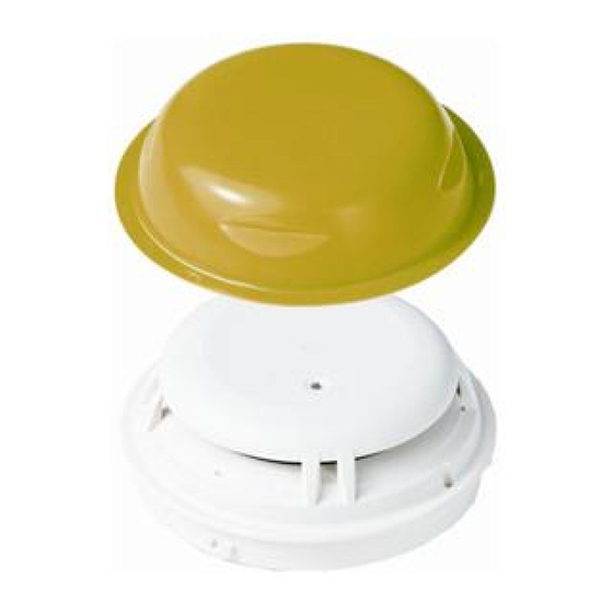
Page 71: Detector Dust Cap
Mounting / Installation Detector dust cap 5.10 Detector dust cap 1. Cover the point detector with the detector dust cap during the construction phase. This will protect the point detector from dust and dirt. 2. Once construction work is complete, remove the detector dust cap from the point detector. -
Page 72: Migration From Collective Detector Line To Addressed Detector Line
One fire detection installation is installed for collective detector lines. Detector bases DB721D are installed on the detector line. Point detectors OOH740 are installed in the detector bases DB721D. 1. Install a fire detection installation with one C-NET detector line 2. -
Page 73: Removing The Diode Unit
Mounting / Installation Migration from collective detector line to addressed detector line 5.11.1 Removing the diode unit Removing the diode unit 1 Detector base DB721D 3 Diode unit 2 Screwdriver size 1 WARNING Falling diode unit Risk of eye damage Wear safety goggles when removing the diode unit! There is no point detector in the detector base DB721D. -
Page 74: Commissioning
Commissioning Commissioning on the C-NET 6 Commissioning 6.1 Commissioning on the C-NET The devices are commissioned via the control panel. The exact procedure is described in the control panel documentation. Conduct a performance check once commissioning is complete. 6.2 Commissioning on a collective detector line The devices are commissioned via the control panel. -
Page 75: Maintenance / Repair
Hot air fan Collective operation In collective operation, the point detector OOH740 has a reduced response time for a period of 3 minutes following the detector line being started up or reset. In this time, the point detector responds faster to test gas or a hot air fan than in normal operation. -
Page 76: Test Mode On The Control Panel
Maintenance / Repair Testing the point detector 7.2.1 Test mode on the control panel The fire detectors are highly resistant to deceptive phenomena. Optical fire detectors thus recognize the immediate occurrence of smoke, as typically occurs when testing with test gas, as a deceptive phenomenon and do not trigger an alarm. -
Page 77: Testing The Co Functionality
Maintenance / Repair Testing the point detector If the point detector is in test mode, the following must be noted: In test mode, the point detector responds according to the parameter set selected. This means when the point detector is operated as a heat detector (sensor mode 1), it must be thermally checked as well. -
Page 78: Technical Ambient Supervision Alarm' Performance Check
Maintenance / Repair Testing the point detector 7.2.4.1 'Technical Ambient Supervision Alarm' performance check You cannot test whether the 'Technical Ambient Supervision Message' is functioning correctly with test devices. Checking can only take place indirectly: You must know the current ambient temperature. Enter the following parameters in the 'Cerberus-Engineering-Tool' software: A hysteresis range of 5 °C A temperature threshold which is at least 5 °C below the current ambient... -
Page 79: Specifications
8 Specifications Unless otherwise mentioned, the following data applies: Temperature = 25 °C Air pressure = 1000 hPa (750 Torr) 8.1 Technical data for OOH740 Addressed detector line (C-NET) Detector line Operating voltage (modulated) DC 12…33 V Operating current (quiescent) Typ. - Page 80 Specifications Technical data for OOH740 Device characteristics Response sensitivity (typ.) 3…12 %/m (depending on the parameter set) Permissible wind speed Max. 5 m/s Compensation speed 1/45 voltage increase for detection/h Ambient conditions Permitted ambient temperature -25…+55 °C Storage temperature -30…+70 °C Optimum storage temperature 0…+20 °C...
- Page 81 Specifications Technical data for OOH740 Collective detector line Detector line Operating voltage DC 14…28 V Maximum current connection factor See 'Collective maximum current connection factor' table Quiescent current at: 65…100 A Maximum current connection factor = Maximum current connection factor = 80…125 A...
-
Page 82: Technical Data For Oohc740
Specifications Technical data for OOHC740 8.2 Technical data for OOHC740 Detector line Operating voltage (modulated) DC 12…33 V Operating current (quiescent) Typ. 300…380 µA Maximum current connection factor Quiescent current connection factor Address connection factor Separator connector factor Protocol C-NET Compatibility See 'List of compatibility' Line separator... - Page 83 EN 54-5 EN 54-7 EN 54-17 CEA 4021 International standards IEC 60529 ISO 9001 ISO 9004 VdS guidelines VdS 2806 Siemens standards SN 36350 Approvals 0786-CPD-21067 EC Certificate of Conformity (construction products) VdS approvals G211047 LPCB approvals 126ba/02 FM approvals...
-
Page 84: Dimensions
Specifications Dimensions 8.3 Dimensions OOH740 OOHC740 OOH740 with base DB72x or DB110 OOHC740 with base DB72x or DB110 8.4 Environmental compatibility This device is manufactured using materials and procedures which comply with current environmental protection standards as best as possible. More specifically, the following measures have been... -
Page 85: Index
Index Index Delivery Default parameter set 0, 49 Ambient supervision, 17 Designation plate Application as heat detector Detector base, 65 Sensor mode 1, 25 Installation, 65 Application as neural fire detector Sounder base, 65 Sensor mode 0, 25 Detection behavior of the detector Application as smoke detector Parameter set, 27, 29 Sensor mode 2, 25... - Page 86 Index External alarm indicator, 33 Can be operated in collective mode, 33 Recycling, 84 C-NET, 33 Renovation mode Major renovation work, 33 Sounder base, 33 Required space, 58 Resistance Fire control panel failure PSR720-1, 41, 41, 69 Degraded mode operation, 34 PSR720-2, 69 Hot air fan Screw terminals...
- Page 87 Index Warning level Signal processing of the point detector, 30 Building Technologies A6V10305793_k_en_-- Fire Safety 2013-04-04...
- Page 88 Issued by © 2010-2013 Copyright Siemens Switzerland Ltd Siemens Switzerland Ltd Technical specifications and availability subject to change without notice. Infrastructure & Cities Sector Building Technologies Division International Headquarters Gubelstrasse 22 CH-6301 Zug Tel. +41 41-724 24 24 www.siemens.com/buildingtechnologies Document ID...
Need help?
Do you have a question about the OOH740 and is the answer not in the manual?
Questions and answers