Table of Contents
Advertisement
Quick Links
Advertisement
Table of Contents

Related Manuals for Jetter JX3-CNT


Summary of Contents for Jetter JX3-CNT
- Page 1 JX3-CNT Counter Module 60878106...
- Page 2 In the case of modifications, further developments or enhancements to products shipped in the past, a revised document will be supplied only if required by law, or deemed appropriate by Jetter AG. Jetter AG shall not be liable for errors in form or content, or for missing updates, as well as for damages or disadvantages resulting from such failure.
- Page 3 +49 7141 2550-484 E-mail - Sales: sales@jetter.de E-mail - Technical Hotline: hotline@jetter.de Assignment to product This user manual is an integral part of JX3-CNT: Type: Serial #: Year of manufacture: Order #: To be entered by the customer: Inventory #:...
- Page 4 Significance of this user This document is an integral part of the JX3-CNT: manual Keep this document in a way that it is always at hand until the JX3-CNT will be disposed of. Pass this document on, if the JX3-CNT is sold or loaned/leased out.
-
Page 5: Table Of Contents
Overview of Features and Interfaces ................... 20 Simultaneous Utilization of Interfaces ..................23 Minimum Requirements ....................... 24 Parts and Interfaces of the JX3-CNT Module ................25 Terminal X61 - Internal Block Diagram ..................26 Female Sub-D Connector X62 - Internal Block Diagram ............. 27 Physical Dimensions ........................ - Page 6 Programming - Dual-Channel Counters ................162 Dual-Channel Counter 24 V (X61.A ... X61.C) ................163 Register Description - Dual-Channel Counter 24 V ..............164 5 V Dual-Channel Counter ......................174 Register Description - Dual-Channel Counter 5 V ..............175 Jetter AG...
- Page 7 Example: Recording and Reading Values ................. 231 6.10 Monitoring the State by Means of Collective Bits ..............234 Monitoring the State by Means of Collective Bits ............... 235 Quick Reference - JX3-CNT Appendix Technical Data .......................... 242 Technical Specifications ......................243 Physical Dimensions ........................
-
Page 9: Safety Instructions
JX3-CNT Safety Instructions Safety Instructions Introduction This chapter informs the user of fundamental safety instructions. It also warns the user of residual dangers, if applicable. Furthermore, it contains information on EMC. Contents Topic Page Basic Safety Instructions ................10 Instructions on EMC ..................12... -
Page 10: Basic Safety Instructions
Usage according to the intended conditions of use implies operation in accordance with this user manual. The JX3-CNT has been designed as a peripheral module for use in machines and is intended for connection to an already existing controller. The JX3-CNT is a peripheral module. - Page 11 Jetter AG. The installation of such parts may impair the safety and the proper functioning of the device. Any liability on the part of Jetter AG for any damages resulting from the use of non-original parts and equipment is excluded. Transporting...
-
Page 12: Instructions On Emc
Installation of the Electric Cabinet" published by Jetter AG. The following instructions are excerpts from Application Note 016: Maintain physical separation between signal and power lines. Jetter AG recommend spacings greater than 20 cm. Cables and lines should cross each other at an angle of 90°. - Page 13 JX3-CNT Safety Instructions Downloading Application You can download Application Note 016 from our homepage Note 016 http://www.jetter.de. In order to download Application Note 016 "EMC-Compatible Installation of Electric Cabinets" browse the following path: Industrial Automation/Support/Downloads/07_application_notes". Jetter AG...
-
Page 15: Product Description And Design
Overview of Features and Interfaces ............20 Simultaneous Utilization of Interfaces ............23 Minimum Requirements ................24 Parts and Interfaces of the JX3-CNT Module ..........25 Terminal X61 - Internal Block Diagram ............26 Female Sub-D Connector X62 - Internal Block Diagram......27 Physical Dimensions .................. -
Page 16: Product Description - Jx3-Cnt
Oscilloscope function Gate function Counter-controlled digital outputs Operating system update via JetSym Scope of Delivery The following items are included in the scope of delivery of the JX3-CNT module: Jetter Item # Quantity Description 10000686 JX3-CNT 60869252... -
Page 17: Order Reference
JX3-CNT Product Description and Design Order Reference Order Reference The JX3-CNT module can be ordered from Jetter AG by specifying the following item number. Jetter Item # Order Reference 10000686 JX3-CNT Jetter AG... -
Page 18: Jx3 Modules: List Of Documentation
2 Product Description and Design JX3 Modules: List of Documentation Introduction Various documents and software tools will support the user in engineering, installing and programming the JX3-CNT module. You can download these documents and software tools from the Jetter AG homepage http://www.jetter.de. Engineering... - Page 19 JX3-CNT Product Description and Design Installation The following document will support you in installing modules: Installation Instruction It is included in the boxed module JX3-CNT and contains information on: Installation of the module on a DIN rail Terminal assignment ...
-
Page 20: Overview Of Features And Interfaces
Dual-channel counter, 5 V connector X62 Terminal for SSI encoder 24 V power supply for encoders 5 V power supply for encoders Terminal X61, lower 24 V Dual-Channel Counter part 24 V power supply for encoders Jetter AG... - Page 21 JX3-CNT Product Description and Design 24 V Single-Channel Single-channel counter for 24 V pulses Counter X61.I/O1 ... Maximum counter frequency 1 kHz X61.I/O4 For connecting up to 4 single-channel counters, 24 V Positive counting direction only ...
- Page 22 State of digital outputs can be read back If other signals at terminal X61 are used in parallel their number must be reduced accordingly. Special functions, such as gate, strobe and reference function, can be used via multi-purpose I/Os. Jetter AG...
-
Page 23: Simultaneous Utilization Of Interfaces
Product Description and Design Simultaneous Utilization of Interfaces Introduction Several interfaces on the JX3-CNT module use the same terminal points. During engineering, take into account which function is to be used on which interface. There are some restrictions that apply to their simultaneous utilization. -
Page 24: Minimum Requirements
2 Product Description and Design Minimum Requirements Introduction The JX3-CNT module is operated in a system consisting of various components by Jetter AG. In order to ensure proper interaction of these components, the operating system used and the programming tool JetSym must have the release numbers listed below. -
Page 25: Parts And Interfaces Of The Jx3-Cnt Module
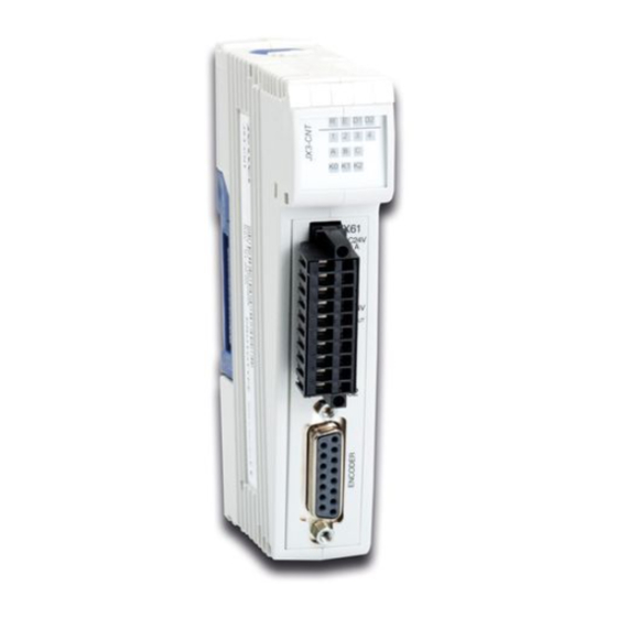
JX3-CNT Product Description and Design Parts and Interfaces of the JX3-CNT Module Parts and Interfaces Number Element Description Upper latch Lets you remove the JX3 module enclosure from the JX3 backplane module JX3 backplane module Connection between JX3 modules; color: blue... -
Page 26: Terminal X61 - Internal Block Diagram
2 Product Description and Design Terminal X61 - Internal Block Diagram Terminal X61: Internal The module JX3-CNT is equipped with 3 digital single-channel counters (24 V) Block Diagram and 1 dual-channel counter (24 V) at input X61. From the block diagram can be seen that the multi-purpose I/Os can be used as inputs/outputs (24 V) and that the signals are forwarded to the logic unit (counter). -
Page 27: Female Sub-D Connector X62 - Internal Block Diagram
JX3-CNT Product Description and Design Female Sub-D Connector X62 - Internal Block Diagram Female Sub-D Connector The Sub-D connector X62 on the module lets you connect either an SSI X62 - Internal Block encoder, or differential signals (5 V). Diagram... - Page 28 24 V power supply voltage to terminal X61.DC24V4.0A. A power supply voltage connected to X61.DC24V4.0A supplies the following terminals with power: X61.DC24V0.5A OUT X62.10: DC +5 V 0.2 A sensor supply X62.12: DC +24 V 0.5 A sensor supply Jetter AG...
-
Page 29: Physical Dimensions
Minimum clearance, below: 25 mm Module Width The width of the JX3-CNT module is 31 mm. If the JX3-CNT module is attached to a JX3 station, its width increases by 25 mm. Mounting Orientation Mount the JX3-CNT module in vertical orientation. -
Page 31: How To Identify The Module
The minimum requirements regarding modules, controllers and software are fulfilled. Information for Hotline If you wish to contact the hotline of Jetter AG in case of a problem, please Requests have the following information on the module JX3-CNT ready: ... -
Page 32: Module Revisions
Each JX3 module features software with unique version numbers which can be read out via module registers. You will need these version numbers when you contact the hotline of Jetter AG in case of a problem. Revision/Version Revision/version numbers of the module JX3-CNT are four-figure values. - Page 33 JX3-CNT How to Identify the Module Software Versions This sample program has been tested with the following software versions: JetSym - version 4.4.3 Controller JC-24x - OS version 3.27.0.00 Module JX3-DIO16 - OS version 2.35.0.00 For other sample programs, refer to JetSym online help.
-
Page 34: Electronic Data Sheet (Eds) With Jc-3Xx
Production-related data can be read from EDS page 1. Register(s) Type Description R 100700 Revision of EDS page 1 R 100701 ... R 100707 string Serial number R 100708 Production date: day R 100709 Production date: month R 100710 Production date: year Jetter AG... - Page 35 JX3-CNT How to Identify the Module Reading an EDS Page To read an EDS page of a JX3-module connected to a JC-3xx proceed as follows: Step Action Select the interface by entering 1 into R 100500. Select the JX3-module by entering the module number into R 100501.
-
Page 36: Electronic Data Sheet (Eds) With Jc-24X
EDS page 1, register 10041 must contain value 1. Register(s) Type Description R 10042 Revision of EDS page 1 R 10043 ... R 10049 string Serial number R 10050 Production date: day R 10051 Production date: month R 10052 Production date: year Jetter AG... - Page 37 JX3-CNT How to Identify the Module Reading an EDS Page To read an EDS page of a JX3-module connected to a JC-24x proceed as follows: Step Action Select the JX3 module by entering the I/O module number into R 10040.
-
Page 38: Electronic Data Sheet (Eds) With Jc-647 And Jx6-Sb(-I)
EDS page 1, register R 3m10041 must contain value 1. Register(s) Type Description R 3m10042 Revision of EDS page 1 R 3m10043 ... R 3m10049 string Serial number R 3m10050 Production date: day R 3m10051 Production date: month R 3m10052 Production date: year Jetter AG... - Page 39 JX3-CNT How to Identify the Module Reading an EDS Page To read out an EDS page proceed as follows: Step Action Select the JX3 module by entering the I/O module number into R 3m10040. Select the EDS page by entering the page number into R 3m10041.
-
Page 40: For Example: Reading Out An Eds On A Jc-3Xx
ModuleName : String[31]; PCB_REV : Int; PCB_Opt : Int; End_Struct; // Defining EDS page 1 JX3_EDS_PAGE1: Struct Version : Int; Sernum : String[19]; TS_Day : Int; TS_Month : Int; TS_Year : Int; End_Struct; End_Type; : JX3_EDS %VL 100500; Jetter AG... - Page 41 JX3-CNT How to Identify the Module EDS0 : JX3_EDS_PAGE0 %VL 100600; EDS1 : JX3_EDS_PAGE1 %VL 100700; End_Var; Task main Autorun // ... End_Task; Reading EDS Page 0 Element Description EDS.Interface 1 = EDS data of the modules within the JX3 station EDS.Module...
-
Page 42: For Example: Reading Out An Eds On A Jc-24X
: Int; Code : Int; Name : String[31]; PCB_REV : Int; PCB_Opt : Int; End_Struct; // Defining EDS page 1 JX3_EDS_PAGE1: Struct Version : Int; Sernum : String[19]; TS_Day : Int; TS_Month : Int; TS_Year : Int; End_Struct; End_Type; Jetter AG... - Page 43 JX3-CNT How to Identify the Module : JX3_EDS %VL 10040; EDS0 : JX3_EDS_PAGE0 %VL 10042; EDS1 : JX3_EDS_PAGE1 %VL 10042; End_Var; Task: End_Task; Reading EDS Page 0 Element Description EDS.Module 2 = Module number EDS.Page 0 = Data of EDS page 0...
-
Page 44: Identifying The Module
3 How to Identify the Module Identifying the Module MR 9 OS version MR 9 indicates the OS version number of the module JX3-CNT. JetSym lets you transfer a new operating system to the JX3-CNT module. Module register properties Values Released OS version: IP#1.0.0.0 ... -
Page 45: Identification Via Nameplate
Each JX3 module can be identified by its nameplate attached to its enclosure. You will need the hardware revision data if you have to contact the hotline of Jetter AG in case of a problem. Nameplate The nameplate of JX3 modules contains the following information: S. - Page 47 JX3-CNT Mounting and Installation Mounting and Installation Purpose of this Chapter This chapter is for supporting you in mounting and installing the JX3-CNT as regards the following points: Planning the wiring of a JX3-CNT Supplying the JX3-CNT with power ...
-
Page 48: Mounting And Installation Interfaces
Multi-Purpose I/Os - Special Functions ............57 Improving the Noise Immunity ..............58 Connecting a Single-Channel Counter, 24 V ..........60 Connecting a Dual-Channel Counter, 24 V ........... 62 Connecting an SSI Encoder ................. 64 Connection of 5 V Incremental Encoders ............. 67 Jetter AG... -
Page 49: Terminal X61 - Pin Assignment
JX3-CNT Mounting and Installation Terminal X61 - Pin Assignment Interfaces of Terminal Terminal X61 supports signals from the following interfaces: Digital 24 V levels as inputs or outputs Strobe, gate and reference input signals as special function ... - Page 50 24 V power supply voltage to terminal X61.DC24V4.0A. A power supply voltage connected to X61.DC24V4.0A supplies the following terminals with power: X61.DC24V0.5A OUT X62.10: DC +5 V 0.2 A sensor supply X62.12: DC +24 V 0.5 A sensor supply Jetter AG...
-
Page 51: Assignment Of Sub-D Connector X62
JX3-CNT Mounting and Installation Assignment of Sub-D Connector X62 Sub-D Connector X62 - Sub-D connector X61 (female) supports signals from the following interfaces: Interfaces SSI encoder Differential dual-channel counter, 5 V Sub-D Connector X62 - Pin Assignment Description X62.1... - Page 52 24 V power supply voltage to terminal X61.DC24V4.0A. A power supply voltage connected to X61.DC24V4.0A supplies the following terminals with power: X61.DC24V0.5A OUT X62.10: DC +5 V 0.2 A sensor supply X62.12: DC +24 V 0.5 A sensor supply Jetter AG...
-
Page 53: Connector Specification - Terminal X61
Mounting and Installation Connector Specification - Terminal X61 Order Data - Connector A 10-pin connector is already included in the scope of delivery of the JX3-CNT module. You can also order this connector separately using the following order data: Designation BU_10_BLZF_F_SW_RM3.5... -
Page 54: Sub-D Connector X62 - Specification Of Mating Connector
4 Mounting and Installation Sub-D Connector X62 - Specification of Mating Connector Specification of Male For information on connector specification refer to the following list: Sub-D Connector Connector Specification Connector technology Soldering technology Type Sub-D, 15 pins, male Configuration Free wiring Jetter AG... -
Page 55: Connecting Sensors And Actuators
JX3-CNT Mounting and Installation Connecting Sensors and Actuators Conductor Design The design of the conductor for connecting sensors must meet the following requirements: Shielded cable with 85 % coverage Drain wire, tin-coated copper Separation of Load and Separation of load voltage and logic voltage has the advantage that all Logic Voltage actuators will be de-energized once the load voltage is switched off. -
Page 56: Multi-Purpose I/Os - Special Functions
Inputs inputs providing the following special functions: Gate Strobe Multi-strobe Reference Please take into account that the maximum number of functions is limited. Related Topics Overview of features and interfaces (see page 20) Jetter AG... -
Page 57: Multi-Purpose I/Os - Special Functions
JX3-CNT Mounting and Installation Multi-Purpose I/Os - Special Functions Using Multi-Purpose I/Os This module lets you use terminals X61.I/O1 ... X61.I/O4 as multi-purpose as Outputs outputs providing the following special functions: Counter-controlled outputs Please take into account that the maximum number of functions is limited. -
Page 58: Improving The Noise Immunity
For differential pulses, use cables with separately shielded twisted pairs. Terminal X61 To ensure the highest level of noise immunity, use extensive shielding measures. Number Element Line to the digital sensor/actuator Shield clamp Drain wire (copper) Counter module JX3-CNT Jetter AG... - Page 59 JX3-CNT Mounting and Installation Connector X62 To ensure the highest level of noise immunity, ensure proper shielding when assembling the connector. Connect the shield in its entire perimeter to the shielding clamp. Use connectors with metallized housing. You can improve the noise immunity of differential signals (e.g. from an ...
-
Page 60: Connecting A Single-Channel Counter, 24 V
Please note that the maximum frequency supported by inputs X61.I/O1 ... X61.I/O4 is 1 kHz. Number Element External power supply unit 24 V Terminal X61 Encoder supply, 24 V, 0.5 A Counting pulses 24 V Counter with a pulse output Jetter AG... - Page 61 JX3-CNT Mounting and Installation Input Terminals for This module lets you connect up to 4 single-channel counters to the following Single-Channel Counter, terminals: 24 V Terminal Point Description X61.I/O1 Multi-purpose I/O (24 V) as input 1 X61.I/O2 Multi-purpose I/O (24 V) as input 2 X61.I/O3...
-
Page 62: Connecting A Dual-Channel Counter, 24 V
X61.B and X61.C. Number Element External power supply unit 24 V Terminal X61 Encoder supply, 24 V, 0.5 A Zero pulse at X61.A Counting pulse at X61.B Counting pulse at X61.C Counter Jetter AG... - Page 63 JX3-CNT Mounting and Installation Connecting an The marking of incremental encoder pinout often differs. Incremental Encoder, If the incremental encoder has got a pinout marked with A, B and Z, connect it 24 V as listed below: Designation Description Terminal Point X61...
-
Page 64: Connecting An Ssi Encoder
Number Element 15-pin female Sub-D connector X62 15-pin male Sub-D connector for connection to X62 Twisted pair conductors for SSI data Shield for twisted pair conductors Shield Shield for twisted pair conductors Twisted pair conductors for SSI clock Jetter AG... - Page 65 JX3-CNT Mounting and Installation Connecting an SSI To connect an SSI encoder, proceed as follows: Encoder Number Element External power supply DC +24 V Terminal X61 15-pin female Sub-D connector: X62 SSI data SSI clock Shielding for SSI data SSI encoder...
- Page 66 X62.12: DC +24 V 0.5 A sensor supply Related Topics Technical specifications (see page 243) Terminal X61 - Pin assignment (see page 49) Female Sub-D connector X62 - Pin assignment (see page 51) Jetter AG...
-
Page 67: Connection Of 5 V Incremental Encoders
JX3-CNT Mounting and Installation Connection of 5 V Incremental Encoders Conductor Design The cable for connecting counting pulses must meet the following requirements: Shielded cable with 85 % coverage Drain wire, tin-coated copper Shielding for Incremental Custom-made incremental encoder cables must meet the following... - Page 68 To connect an incremental encoder, proceed as follows: Number Element External power supply DC +24 V Terminal X61 15-pin female Sub-D connector X62 Differential input K2 Differential input K1 Differential input K0, zero pulse Option: separately shielded twisted pair conductors Incremental encoder Jetter AG...
- Page 69 JX3-CNT Mounting and Installation Complete Wiring Due to compatibility reasons, some signals are assigned to two pins of the Diagram Sub-D connector. Number Element External power supply DC +24 V Terminal X61 15-pin female Sub-D connector X62 Differential input K2...
- Page 70 Use a shield clamp to provide additional grounding of the shield. Related Topics Technical specifications (see page 243) Terminal X61 - Pin assignment (see page 49) Female Sub-D connector X62 - Pin assignment (see page 51) Jetter AG...
-
Page 71: 4.2 Indicators And Leds
JX3-CNT Mounting and Installation 4.2 Indicators and LEDs LEDs on the Counter The module JX3-CNT is equipped with the following LEDs: Module JX3-CNT 4 LEDs indicating the operating status 10 LEDs indicating the status of counters or I/Os... -
Page 72: Leds On The Module Jx3-Cnt
LEDs on the Module JX3-CNT Introduction The module JX3-CNT indicates conditions and errors via its LEDs. This feature lets you directly locate an error. LEDs on the Module The JX3-CNT module is equipped with 14 LEDs which indicate conditions and JX3-CNT errors. Color Description "R"... - Page 73 OS of the module is not valid OS update is running Meaning of Status LEDs The amber LEDs on the module JX3-CNT indicate the digital signal level of for X61 connected hardware. This lets you easily check, for instance, whether the connected counter is sending counting pulses.
- Page 74 4 Mounting and Installation Meaning of Status LEDs The amber LEDs on the module JX3-CNT indicate the digital signal level of for X62 connected hardware. This lets you easily check whether the connected counter is sending counting pulses. The amber LEDs are assigned to the following inputs on X62: ...
-
Page 75: 4.3 Installing, Replacing, And Removing The Module
JX3-CNT Mounting and Installation 4.3 Installing, Replacing, and Removing the Module Introduction This chapter covers installation, replacement and removal of JX3 modules. Contents Topic Page Installing a JX3 Peripheral Module on a DIN Rail ........76 Replacing a JX3 Peripheral Module ............. 77 Removing a JX3 Peripheral Module from the DIN Rail ........ -
Page 76: Installing A Jx3 Peripheral Module On A Din Rail
DIN rail. Slide the JX3 peripheral module to the other modules of the JX3 station. Related Topics Replacing a JX3 peripheral module (see page 77) Removing a JX3 peripheral module from the DIN rail (see page 79) Jetter AG... -
Page 77: Replacing A Jx3 Peripheral Module
JX3-CNT Mounting and Installation Replacing a JX3 Peripheral Module Removing the JX3 To remove the JX3 enclosure of the JX3 peripheral module from the JX3 Enclosure backplane module proceed as follows: Step Action Remove power from the JX3 station. Press the upper and lower latches. - Page 78 4 Mounting and Installation Related Topics Installing JX3 peripheral modules on a DIN rail (see page 76) Removing a JX3 peripheral module from the DIN rail (see page 79) Jetter AG...
-
Page 79: Removing A Jx3 Peripheral Module From The Din Rail
JX3-CNT Mounting and Installation Removing a JX3 Peripheral Module from the DIN Rail Removing To remove a JX3 peripheral module from a rail to DIN EN 50022 proceed as follows: Step Action Remove power from the JX3 station. Slide the adjacent JX3 peripheral modules aside. By doing so, the JX3 backplane to the other JX3 peripheral modules is disconnected. - Page 80 4 Mounting and Installation Step Action Remove the JX3 peripheral module from the DIN rail. Related Topics Installing JX3 peripheral modules on a DIN rail (see page 76) Replacing a JX3 peripheral module (see page 77) Jetter AG...
-
Page 81: Initial Commissioning
Counting by means of single-channel counter Connecting an incremental encoder Prerequisites To be able to commission the JX3-CNT module the following prerequisites have to be fulfilled: The module JX3-CNT is connected to a JetControl PLC. The controller is connected to a PC. -
Page 82: Preparatory Work For Initial Commissioning
Following a correct commissioning, the condition of the LEDs is as follows: Status No error, communication is active 1 ... 4 A ... C Status Status: OK, but no encoder installed Status Status: OK, but no encoder installed Jetter AG... -
Page 83: Initial Commissioning Along With A Jc-3Xx
JX3-CNT Initial Commissioning Initial Commissioning Along with a JC-3xx Task Connect a 24 V signal line to terminal X61.I/O1 and have the count value of the single-channel counter displayed in the setup pane. Configuration The initial commissioning is based on the following configuration:... - Page 84 5 Initial Commissioning Number Description Value Count value after some digital counting pulses (24 V) at X61.I/O1 Jetter AG...
-
Page 85: Initial Commissioning Along With A Jc-24X
Counter module JX3-CNT X61.A, B, C Terminal for 24 V dual-channel counter Determining the Register The status of the module JX3-CNT is assigned to module register MR 0. The Number register number is composed of the following digits: Element Description... - Page 86 5 Initial Commissioning Counting Signals at Make the count value of the module JX3-CNT available in JetSym's Setup Dual-Channel Counter pane and register number 3000. via JetSym To count signals at X61.A ... X61.C of the digital dual-channel counter, proceed as follows: ...
-
Page 87: Programming
JX3-CNT Programming Programming Purpose of this Chapter This chapter is for supporting you in programming the JX3-CNT module in the following fields of activity: Determining the register numbers depending on the system configuration. Getting familiar with the address ranges of counters ... -
Page 88: Abbreviations, Module Register Properties And Formats
0 or undefined (e.g. release/version number) Takes effect Immediately Write access Always Data type Integer Number Formats The number formats used in this document are listed in the following table: Notation Numerical Format Decimal 0x100 Hexadecimal 0b100 Binary Jetter AG... - Page 89 JX3-CNT Programming JetSym Sample The notation for sample programs used in this document is listed in the Programs following table: Notation Description Var, When, Task Keyword BitClear(); Commands 100 0x100 0b100 Constant numerical value // This is a comment Comment // ...
-
Page 90: 6.1 Register And I/O Numbering For Jx3 Modules
6.1 Register and I/O Numbering for JX3 Modules Introduction The modules supplied by Jetter AG can carry out a great number of functions which can be called up by the user via registers. Each register and each digital input or output has been designated by an unambiguous number. -
Page 91: Registers And Module Registers
Definition - Module Module registers let you read process, configuration and diagnostics data from Registers the module JX3-CNT, or write such data to it. The module register number within a module is unique. Definition - Registers Direct access to registers is possible from: an application program ... -
Page 92: I/O Module Numbers In The Jx2 System Bus
Several JX3 modules have been connected to a JC-24x controller via Numbering JX2 system bus. STOP LOAD Jetter ADDRESS Jetter Jetter JetWeb JC-246 HIGH SER1 INPUT INPUT OUTPUT SER2 DC24V DC24V 0,5A 0,5A Number Module I/O Module Number JC-24x JX3-BN-CAN JX3-AO4 JX3-DIO16 JX3-BN-CAN JX3-DI16 JX3-AI4 Jetter AG... -
Page 93: Register And I/O Numbers With Jc-24X And Jm-D203-Jc-24X
JX3-CNT Programming Register and I/O Numbers with JC-24x and JM-D203-JC-24x Register Numbers for Register numbers for JX3 modules connected to a JC-24x and JX3 Modules JM-D203-JC24x consist of the following elements: Element Meaning Value Range I/O module number on the JX2 system bus - 2 0 ... -
Page 94: Register And I/O Numbers With Jc-3Xx
Several JX3 modules are connected to a controller JC-3xx. R E D1 D2 Jetter Jetter LOAD STOP SHLD SHLD SHLD DC24V DC24V 1,2A 0,5A SHLD Number Module Module Number Registers JC-3xx refer to documentation on JC-3xx JX3-AO4 10002zzzz 1000002zz JX3-PS1 JX3-DIO16 10010zzzz 1000010zz Jetter AG... -
Page 95: Register And I/O Numbers For Jc-647 With Jx6-Sb(-I)
JX3-CNT Programming Register and I/O Numbers for JC-647 with JX6-SB(-I) Register Numbers for Register numbers for JX3 modules connected to a JC-647 equipped with a JX3 Modules JX6-SB(-I) consist of the following elements: Element Meaning Value Range Submodule socket 1 ... 3 I/O module number on the JX2 system bus - 2 0 ... -
Page 96: Register And I/O Numbers For Jc-800 With Jx6-Sb(-I)
Element Meaning Value Range 2..3 Input 2..3 Output Module board number 1 ... 3 System bus module 1 ... 2 I/O module number on the JX2 system bus 2 ... 32 Module specific I/O number 1 ... 16 Jetter AG... -
Page 97: Register And I/O Numbers For Jc-9Xx With Jx6-Sb(-I)
JX3-CNT Programming Register and I/O Numbers for JC-9xx with JX6-SB(-I) Register Numbers for Register numbers for JX3 modules connected to a JC-9xx equipped with a JX3 Modules JX6-SB(-I) consist of the following elements: Element Meaning Value Range Module board number 1 ... -
Page 98: Register Access To Jx3 Modules On The Jx2 System Bus
Direct Register Access to JX3 Modules on the JX2 System Bus ....99 Example - Direct Register Access .............. 100 Indirect Register Access to JX3 Modules on the JX2 System Bus ..... 101 Example - Indirect Register Access ............103 Module Registers for Indirect Register Access ........... 104 Jetter AG... -
Page 99: Direct Register Access To Jx3 Modules On The Jx2 System Bus
JX3-CNT Programming Direct Register Access to JX3 Modules on the JX2 System Bus Direct Register Access At direct register access, a module register of the module is directly assigned to a register number. Via this register, the value of the module register can be read and written. -
Page 100: Example - Direct Register Access
For other sample programs, refer to JetSym online help. JetSym ST Program // Status register State : Int %VL 3000; End_Var; Task 0 // Waiting for the power supply to fail When BIT_CLEAR(State, 2) Continue; // Error handling routine End_Task; Jetter AG... -
Page 101: Indirect Register Access To Jx3 Modules On The Jx2 System Bus
JX3-CNT Programming Indirect Register Access to JX3 Modules on the JX2 System Bus Overview of Registers At indirect register access, the following module registers are used: Registers Description MR 7 Index for indirect register access MR 8 Value for indirect register access... - Page 102 Possible sources are: Various tasks of the application program in the controller JetSym setup Visualization Related Topics Register description for indirect register access (see page 104) Example: Indirect register access (see page 103) Jetter AG...
-
Page 103: Example - Indirect Register Access
JX3-CNT Programming Example - Indirect Register Access Objective This example demonstrates how to indirectly enter values into module registers. The exact functionality of the digital filter used in this example is not relevant. Task Set the digital filters of inputs IN1 through IN3 on the module JX3-DIO16 to 16 ms. -
Page 104: Module Registers For Indirect Register Access
0 .. 9,999 Value after reset MR 8 Value for Indirect Register Access Via MR 8, a module register value is read or written. Module Register Properties Values Dependent on the specified module register number in MR 7 Jetter AG... -
Page 105: 6.3 Address Ranges Of Counters
JX3-CNT Programming 6.3 Address Ranges of Counters Introduction Each counter and some of the special features have got an address range of their own. The address ranges of the different counters are structured in a way that the same features of different counters have got the same register number ending (last two places). -
Page 106: Address Ranges Of Counters
Module register numbers on JX3 modules connected to a JC-3xx consist of Register Number on the following elements: JX3 Modules Element Description Value Range Module number of the module within the JX3 02 ... 17 station zzzz Address of the counter/function 0 ... 9999 Jetter AG... - Page 107 JX3-CNT Programming Explanation of the To explain identical features that apply to different counters, the variable "y" Variable y in this Manual has been introduced. The variable "y" is a placeholder for the counter used. Registers Description MR 1100 ... 1199 y = 1 Single-channel counter (24 V) # 1 at X61.I/O1...
-
Page 108: 6.4 Zeroing A Counter
6 Programming 6.4 Zeroing a Counter Introduction The module JX3-CNT lets you set any counter to a specific value. This can be done before, or while you use the counter. Comparison: Setting a Hardware referencing is the most accurate method. -
Page 109: Zeroing A Counter By Means Of Software
JX3-CNT Programming Zeroing a Counter by Means of Software Zeroing by Means of For zeroing by means of software, proceed as follows: Software Step Action Stop the counter to prevent accidental count values. Poll the status register to see whether... -
Page 110: Zeroing A Counter By Means Of Hardware
Simultaneous utilization of interfaces (see page 23) 24 V single-channel counter A, B, C at X61 (see page 148) 24 V dual-channel counter X61.A ... X61.C (see page 148) 5 V dual-channel counter (see page 175) Jetter AG... -
Page 111: 6.5 Multi-Purpose I/Os - Additional Functions
JX3-CNT Programming 6.5 Multi-Purpose I/Os - Additional Functions Introduction This module lets you configure additional functions for each counter. The following additional functions cannot be applied to inputs X61.I/O1 ... X61.I/O4 if they are used as counters: • Gate Function •... -
Page 112: Gate Function
6 Programming 6.5.1 Gate Function Introduction This chapter covers the gate function of the module JX3-CNT. Gate Function - The gate function can be used for the following counters: Applicability Registers Description MR 1500 ... 1599 Single-channel counter (24 V) at X61.A MR 1600 ... -
Page 113: Gate Function
JX3-CNT Programming Gate Function Gate Function - The gate function is a hardware enable. Basic Principle The gate function can also be negated. & MR 1yzz Number Description Actual counter Gate function: The count is copied into MR 1yzz only if the logic level at input E_2 is "1". - Page 114 Simultaneous utilization of interfaces (see page 23) 24 V single-channel counter A, B, C at X61 (see page 148) 24 V dual-channel counter X61.A ... X61.C (see page 164) 5 V dual-channel counter (see page 175) Jetter AG...
-
Page 115: Example: Gate Function
JX3-CNT Programming Example: Gate Function Task Use the gate function of the module JX3-CNT for counting purposes. Solution Use one of the multi-purpose inputs as gate input. Sample Configuration This example is based on the following configuration: Number Element Description... - Page 116 JX3_CNT_Inc_A_Gatemask : Int %VL 100021526; End_Var; Task t_Main Autorun // Assigning X61.I/O1 as gate input, defining the gate mask: JX3_CNT_Inc_A_Gatemask := 0b00000001; // Enabling gate: JX3_CNT_Inc_A_Command := 34; // Enabling the counter: JX3_CNT_Inc_A_Command := 30; // Netxt step End_Task; Jetter AG...
-
Page 117: Strobe Function
JX3-CNT Programming 6.5.2 Strobe Function Introduction This chapter covers the strobe function of the module JX3-CNT. Strobe Function - The strobe function can be used for the following counters: Applicability Registers Description MR 1500 ... 1599 Single-channel counter (24 V) at X61.A MR 1600 ... -
Page 118: Strobe Function
That you can make proper use of the strobe function, the following requirements must be fulfilled: An external counter providing counting pulses has been connected. A strobing signal has been connected to one of the multi-purpose I/Os. The edge of the strobe input has been defined. Jetter AG... - Page 119 JX3-CNT Programming Strobe Function - The multi-purpose I/Os let you, in strobe mode, save count values in a module Diagram register triggered by hardware pulses. Number Description Counting pulses at the counter input Strobe input, set to positive edge Strobe input, set to negative edge...
- Page 120 Simultaneous utilization of interfaces (see page 23) 24 V single-channel counter A, B, C at X61 (see page 148) 24 V dual-channel counter X61.A ... X61.C (see page 164) 5 V dual-channel counter (see page 175) Jetter AG...
-
Page 121: Example: Strobe Function
JX3-CNT Programming Example: Strobe Function Task Use the strobe function of the module JX3-CNT along with a counter. Solution Use one of the multi-purpose inputs as strobe input. Sample Configuration This example is based on the following configuration: Number Element... - Page 122 // Enabling the strobe function: JX3_CNT_Inc24V_Cmd := 36; // Enabling the counter: JX3_CNT_Inc24V_Cmd := 30; // The counter is now active and is counting. // Whenever a positive signal arrives at X61.I/O1, the counter reading is stored. End_Task; Jetter AG...
-
Page 123: Multi-Strobe Function
JX3-CNT Programming 6.5.3 Multi-Strobe Function Introduction This chapter covers the multi-strobe function of the module JX3-CNT. Multi-Strobe Function - The multi-strobe function can be used for the following counters: Applicability Registers Description MR 1500 ... 1599 Single-channel counter (24 V) at X61.A MR 1600 ... -
Page 124: Multi-Strobe Function
Counter register 1y03 The count value to be incremented/decremented depending on the state of input E2. This input has been defined in the application program. Multi-purpose input X61.I/O1 ... X61.I/O4 Counting pulses at the counter input Jetter AG... - Page 125 JX3-CNT Programming Assigning Multi-Strobe The multi-strobe function can be used with all counters X61.A ... X61.C, as to a Counter well as with dual-channel counters. The multi-strobe function can be assigned only to one counter at a time. Number Description No counter assigned Single-channel counter A at X61.A...
- Page 126 24 V single-channel counter A, B, C at X61 (see page 148) 24 V dual-channel counter X61.A ... X61.C (see page 164) 5 V dual-channel counter (see page 175) SSI counter (see page 187) Jetter AG...
-
Page 127: Multi-Strobe - Description Of Registers
JX3-CNT Programming Multi-Strobe - Description of Registers Address Range of Registers Description Multi-Strobe Function MR 900 ... MR 949 Multi-strobe function MR 900 Status Register - Multi-Strobe In MR 900 the module signals status messages on multi-strobe. To reset the status register, issue command 4. - Page 128 Values 0 ... 15 Type of access Read and write access MR 910 ... MR 925 Multi-Strobe Data All strobe values are consecutively stored to the array MR 910 ... MR 925. Module Register Properties Multi-strobe data [0] Jetter AG...
- Page 129 JX3-CNT Programming Multi-strobe data [1] Multi-strobe data [2] Multi-strobe data [3] Multi-strobe data [4] Multi-strobe data [5] Multi-strobe data [6] Multi-strobe data [7] Multi-strobe data [8] Multi-strobe data [9] Multi-strobe data [10] Multi-strobe data [11] Multi-strobe data [12] Multi-strobe data [13]...
-
Page 130: Example: Multi-Strobe Function
6 Programming Example: Multi-Strobe Function Task Use the strobe function provided by the module JX3-CNT. Solution Configure one of the multi-purpose inputs as multi-strobe input. Sample Configuration This example is based on the following configuration: Number Element Description JC-3xx Controller... - Page 131 JX3-CNT Programming JetSym STX Program JX3_CNT_Cmd : Int %VL 100020001; JX3_CNT_Inc24V_Cmd : Int %VL 100021801; JX3_CNT_Inc24V_RisingEdge : Int %VL 100021828; JX3_CNT_MultiStrobeCmd : Int %VL 100020901; JX3_CNT_MultiStrobeAs : Int %VL 100020902; JX3_CNT_MultiStrobeCnt : Int %VL 100020903; End_Var; Task t_Main Autorun // Enabling voltage supply for incremental encoder JX3_CNT_Cmd := 3;...
-
Page 132: Reference Function
6 Programming 6.5.4 Reference Function Introduction This chapter covers the reference function of the module JX3-CNT. The module JX3-CNT lets you reference the following counters: Single-channel counters Dual-channel counters Differences in There are differences in referencing single-channel and dual-channel... -
Page 133: Reference Function For Single-Channel Counters
JX3-CNT Programming Reference Function For Single-Channel Counters Single-Channel Counter - On single-channel counters, reference positions can be set using the positive Example: Setting the or negative signal edge. Reference Position In this example, the counter is reset to zero at the point in time t2 by a negative edge at input X61.I/O1. - Page 134 = 5, 6 or 7 Related Topics Overview of features and interfaces (see page 20) Simultaneous utilization of interfaces (see page 23) 24 V single-channel counter A, B, C at X61 (see page 148) Jetter AG...
-
Page 135: Example: Reference Function For Single-Channel Counters
JX3-CNT Programming Example: Reference Function For Single-Channel Counters Task Use the reference function provided by the module JX3-CNT for a single-channel counter connected to input X61.A. Solution Use one of the multi-purpose inputs as reference input and configure it accordingly. - Page 136 // Enabling the reference function: JX3_CNT_Inc_A_Cmd := 38; // Enabling the counter: JX3_CNT_Inc_A_Cmd := 30; // The counter is now active and is counting. // The counter reading is reset to 0x1234 if the signal at X61.I/O1 has a rising edge. End_Task; Jetter AG...
-
Page 137: Reference Function For Dual-Channel Counters
JX3-CNT Programming Reference Function For Dual-Channel Counters Dual-Channel Counter - Prerequisites: Example: Setting the A reference signal has been connected to one of the inputs Reference Position X61.I/O1 ... X61.I/O4. An incremental encoder with zero pulse signal has been connected to X61.A ... X61.C or X62. - Page 138 Related Topics Overview of features and interfaces (see page 20) Simultaneous utilization of interfaces (see page 23) 24 V dual-channel counter X61.A ... X61.C (see page 164) 5 V dual-channel counter (see page 175) Jetter AG...
-
Page 139: Example: Reference Function For Dual-Channel Counters
Example: Reference Function For Dual-Channel Counters Task Use the reference function for dual-channel counters provided by the module JX3-CNT. An incremental encoder with zero pulse signal is connected to the 24 V dual-channel counter input. Solution Use one of the multi-purpose inputs as reference input and configure it accordingly. - Page 140 JX3_CNT_Inc24V_Cmd := 30; // The counter is now active and is counting. // The counter reading is reset to zero if X61.I/O1 is low AND the edge at X61.A (K0) is rising. When (JX3_CNT_Inc24V_Status & 0x08000000) Continue; End_Task; Jetter AG...
-
Page 141: Programming Single-Channel Counters (24 V)
JX3-CNT Programming 6.6 Programming Single-Channel Counters (24 V) Introduction This chapter describes how to program single-channel counters (24 V) connected to this module. Contents Topic Page Single-Channel Counter I/O1 ... I/O4............142 Register Description - Single-Channel Counter I/O1 ... I/O4 ...... 143 Example - Single-Channel Counter I/O1 ... -
Page 142: Single-Channel Counter I/O1
A single-channel counter (24 V) must be enabled and disabled in the Counters application program. Related Topics Overview of features and interfaces (see page 20) Simultaneous utilization of interfaces (see page 23) Registers and I/O numbers with JC-3xx controllers (see page 94) Jetter AG... -
Page 143: Register Description - Single-Channel Counter I/O1
JX3-CNT Programming Register Description - Single-Channel Counter I/O1 ... I/O4 Address Range - Module Register(s) Description Counter 1 ... Counter 4 1100 ... 1199 Counter 1 (X61.I/O1) 1200 ... 1299 Counter 2 (X61.I/O2) 1300 ... 1399 Counter 3 (X61.I/O3) 1400 ... 1499 Counter 4 (X61.I/O4) - Page 144 Incoming counting pulses will increment this value. Module Register Properties Values 0 ... +4,294,967,295 Value after reset Read Reads the current count value Write Sets the count value to a new value. Count value Positive: The counter counts only in positive direction. Jetter AG...
-
Page 145: Example - Single-Channel Counter I/O1
This sample program has been tested with the following software versions: JetSym - version 4.4.3 Controller JC-350 - OS version 1.14.0.00 Module JX3-CNT - OS version 1.02.0.00 For other sample programs, refer to JetSym online help. JetSym STX Program JX3_CNT_IO3_Status : Int %VL 100021300;... -
Page 146: Single-Channel Counter (Counter A, B, C At X61)
MR 1y20 lets you directly read out or write the maximum value of the trailing indicator. Module registers 1y08 and 1y09 let you specify the lower and upper limit. The status register of the single-channel counter indicates whether the limits have been exceeded. Jetter AG... - Page 147 JX3-CNT Programming Enabling the Digital Filter Activate the digital filter to eliminate noise (e.g. spikes) from the input signal. for Single-Channel Counter (24V) Related Topics Overview of features and interfaces (see page 20) Simultaneous utilization of interfaces (see page 23) ...
-
Page 148: Register Description - Single-Channel Counter A, B, C At X61
1y00. Bit 24 Strobe value received? MR 1y04 contains a new strobe value. Bit 25 Counter blocked by gate function? There is no input signal enabling the counter Jetter AG... - Page 149 JX3-CNT Programming Meaning of the individual bits Bit 26 Counter enabled? The counter has been started enabled by the application program. Bit 27 Reference set? This bit is 0 if the counter has not yet been referenced. No edge detected at X61.I/O1 ... X61.I/O4.
- Page 150 6 Programming MR 1y01 Command Register of Counter Channel MR 1y01 lets you configure functions provided by the module JX3-CNT. Commands Enable the counter Disable the counter Positive counting direction Negative counting direction Enable gate function Disable gate function Enable strobe function...
- Page 151 JX3-CNT Programming MR 1y04 Strobe Register If a strobe signal is present at the assigned multi-purpose I/O, the current count value is copied from MR 1y03 to MR 1y04. Module Register Properties Values -2,147,483,648 ... +2,147,483,647 Type of access Read only...
- Page 152 MR 1y14 lets you define a divisor. The count value contained in MR 1y03 is divided by the value of MR 1y14. The result is stored to MR 1y18. Module Register Properties Values -2,147,483,648 ... +2,147,483,647 Value after reset Jetter AG...
- Page 153 JX3-CNT Programming MR 1y15 Offset for Scaling Function MR 1y15 lets you define an offset. An offset is added to the count value in MR 1y03, multiplication and division factors. The result is stored to MR 1y18. Module Register Properties Values -2,147,483,648 ...
- Page 154 The value is accepted only if the input signal is present for a period longer than time T. Calculation: where T = t Module Register Properties Values 0 ... +65,535 Type of access Read and write access Value after reset 0 (default: OFF) Jetter AG...
- Page 155 JX3-CNT Programming MR 1y26 Gate Mask The gate mask lets you assign the gate function to one of the inputs. This register is bit-coded (value range 0 ... 15). Module Register Properties Values 0 ... 15 For the gate mask values refer to the table below:...
- Page 156 For the values "Strobe - Falling edge" refer to the table below: Value Description 0b0000 All inputs are disabled 0b0001 X61.I/O 1 is enabled 0b0010 X61.I/O 2 is enabled 0b0100 X61.I/O 3 is enabled 0b1000 X61.I/O 4 is enabled 0b1010 X61.I/O 2 and X61.I/O 4 are enabled Jetter AG...
- Page 157 JX3-CNT Programming Value Description 0b1111 All inputs are enabled MR 1y32 Reference - Rising Edge The input mask "Reference - Rising edge" lets you define which inputs X61.I/O1 ... X61.I/O4 are to respond to the rising edge of the reference signal.
- Page 158 0 ... +4,294,967,296 Example: The lower modulo limit is 0, and the upper limit is 360. The value contained in MR 1y42 is 123. Thus, the number of resulting revolutions is 123 in the case of a full circle. Jetter AG...
-
Page 159: Example: Single-Channel Counter At X61.A
Use a single-channel counter at input X61.B with the following features: scaled output value, trailing indicator, gate, strobe and reference function. Configuration: 1 counter module JX3-CNT and 1 I/O module JX3-DIO16 are connected to a controller JC-3xx. An external sensor supplies counting pulses (24 V). - Page 160 := 7; JX3_CNT.SingleCounter_B.UserScaling_Div := 8; JX3_CNT.SingleCounter_B.UserScaling_Ofs := 2210; JX3_CNT.SingleCounter_B.Cnt_Limit_Low := -24564716; JX3_CNT.SingleCounter_B.Cnt_Limit_High := 38765468; // Declaring the gate function: JX3_CNT.SingleCounter_B.GateIN_Mask := 0b0001; // Gate function is low-active: JX3_CNT.SingleCounter_B.GateActiveHigh := 0b0001; // Enabling the gate function: JX3_CNT.SingleCounter_B.Command := 34; Jetter AG...
- Page 161 JX3-CNT Programming // Declaring the strobe function: // Positive edge at X61.I/O3 JX3_CNT.SingleCounter_B.StrobeTrigRisingE := 0b0100; // Negative edge at X61.I/O2 JX3_CNT.SingleCounter_B.StrobeTrigFallingE := 0b0010; // Enabling the strobe function: JX3_CNT.SingleCounter_B.Command := 36; // Declaring the reference function: JX3_CNT.SingleCounter_B.RefOffset := -123; // Negative edge at X61.I/O4 JX3_CNT.SingleCounter_B.RefTrigFallingE...
-
Page 162: 6.7 Programming - Dual-Channel Counters
This chapter describes how to program dual-channel counters connected to this module. Contents Topic Page Dual-Channel Counter 24 V (X61.A ... X61.C)..........163 Register Description - Dual-Channel Counter 24 V ........164 5 V Dual-Channel Counter ................174 Register Description - Dual-Channel Counter 5 V ........175 Jetter AG... -
Page 163: Dual-Channel Counter 24 V (X61.A
JX3-CNT Programming Dual-Channel Counter 24 V (X61.A ... X61.C) Introduction This module lets you connect a dual-channel counter (24 V) to terminals X61.A ... X61.C. Properties of Dual-channel counter for 24 V pulses with zero pulse signal Dual-Channel Counters ... -
Page 164: Register Description - Dual-Channel Counter 24 V
Reference set? This bit is 0 if the counter has not yet been referenced. No edge detected at X61.I/O1 ... X61.I/O4. This bit is 1 if an edge is detected at input X61.I/O1 ... X61.I/O4 configured as reference input. Jetter AG... - Page 165 Module Register Properties Type of access Read and write access MR 1801 Command Register of Counter Channel MR 1801 lets you configure functions provided by the module JX3-CNT. Commands Enable counter Disable counter Enable gate function Disable gate function...
- Page 166 MR 1806 contains the duration of a period. This is the interval in µs between two level changes-(from high to high) of the last increment. Module Register Properties Values 0 ... +4,294,967,296 Unit Microseconds Type of access Read only Jetter AG...
- Page 167 JX3-CNT Programming MR 1808 Lower Limit MR 1808 lets you define the lower limit value for the counter. If the counter falls below this value, bit 19 in status register 1800 is set. Module Register Properties Values -2,147,483,648 ... +2,147,483,647...
- Page 168 Trailing Indicator - Maximum Value A trailing indicator shows the minimum and maximum count value. MR 1821 contains the highest count value that has been counted and stored to MR 1803. Module Register Properties Values -2,147,483,648 ... +2,147,483,647 Value after reset +2,147,483,647 Jetter AG...
- Page 169 JX3-CNT Programming MR 1823 Digital Filter The digital filter, that can be activated if required, lets you filter out interferences from the input signal, such as spikes (depending on the settings). Operating principle: This filter lets you define a different sampling time. As a result, the digital filter acts like a low-pass filter.
- Page 170 X61.I/O4 are to respond to the rising edge of a strobe. This register is bit-coded (value range 0 ... 15). Module Register Properties Values 0 ... 15 For the values "Strobe - Rising edge" refer to the table below: Jetter AG...
- Page 171 JX3-CNT Programming Value Description 0b0000 All inputs are disabled 0b0001 X61.I/O 1 is enabled 0b0010 X61.I/O 2 is enabled 0b0100 X61.I/O 3 is enabled 0b1000 X61.I/O 4 is enabled 0b1010 X61.I/O 2 and X61.I/O 4 are enabled 0b1111 All inputs are enabled...
- Page 172 MR 1831 lets you set the referencing function for the respective input. Evaluation can be low-active or high-active. This register is bit-coded (value range 0 ... 15). Module Register Properties Values 0 ... 15 Reference is high-active Reference is low-active Jetter AG...
- Page 173 JX3-CNT Programming MR 1840 Modulo - Lower Limit MR 1840 lets you define a lower limit for the modulo function. It is not mandatory that the count value starts at 0. Module Register Properties Values -2,147,483,648 ... +2,147,483,647 Value after reset...
-
Page 174: Dual-Channel Counter
Overview of features and interfaces (see page 20) Simultaneous utilization of interfaces (see page 23) Gate function (see page 133) Reference function (see page 118) Strobe function (see page 124) Multi-strobe function (see page 124) Jetter AG... -
Page 175: Register Description - Dual-Channel Counter 5 V
JX3-CNT Programming Register Description - Dual-Channel Counter 5 V Address Range - Registers Description Dual-Channel Counter at MR 1900 ... MR 1999 5 V dual-channel counter MR 1900 Status Register - Counter Module The module indicates status messages of the dual-channel counter (5 V) in MR 1900. - Page 176 Module Register Properties Type of access Read and write access MR 1901 Command Register of Counter Channel MR 1901 lets you configure functions provided by the module JX3-CNT. Commands Enable counter Disable counter Enable gate function Disable gate function...
- Page 177 JX3-CNT Programming MR 1903 Unscaled Count Value The unscaled count value is entered into MR 1903. To change the initial value, enter a new value into this module register. Module Register Properties Values -2,147,483,648 ... +2,147,483,647 MR 1904 Strobe Register If a hardware pulse is present at the assigned multi-purpose I/O, the current count value is copied from MR 1903 to MR 1904.
- Page 178 MR 1914 lets you define a divisor. The count value contained in MR 1903 is divided by the value of MR 1914. The result is stored to MR 1918. Module Register Properties Values -2,147,483,648 ... +2,147,483,647 Value after reset Jetter AG...
- Page 179 JX3-CNT Programming MR 1915 Offset for Scaling Function MR 1915 lets you define an offset. An offset is added to the count value in MR 1903, multiplication and division factors. The result is stored to MR 1918. Module Register Properties Values -2,147,483,648 ...
- Page 180 Value after reset 0 (default: OFF) MR 1926 Gate Mask The gate mask lets you assign the gate function to one of the inputs. This register is bit-coded (value range 0 ... 15). Module Register Properties Values 0 ... 15 Jetter AG...
- Page 181 JX3-CNT Programming For the gate mask values refer to the table below: Value Description 0b0000 All inputs are disabled 0b0001 X61.I/O 1 is enabled 0b0010 X61.I/O 2 is enabled 0b0100 X61.I/O 3 is enabled 0b1000 X61.I/O 4 is enabled 0b1010 X61.I/O 2 and X61.I/O 4 are enabled...
- Page 182 0b0000 All inputs are disabled 0b0001 X61.I/O 1 is enabled 0b0010 X61.I/O 2 is enabled 0b0100 X61.I/O 3 is enabled 0b1000 X61.I/O 4 is enabled 0b1010 X61.I/O 2 and X61.I/O 4 are enabled 0b1111 All inputs are enabled Jetter AG...
- Page 183 JX3-CNT Programming MR 1930 Reference Mask The reference mask lets you assign the reference function to one of the inputs. This register is bit-coded (value range 0 ... 15). Module Register Properties Values 0 ... 15 For the reference mask values refer to the table below:...
- Page 184 0 ... +4,294,967,296 Example: The lower modulo limit is 0, and the upper limit is 360. The value contained in MR 1942 is 123. Thus, the number of resulting revolutions is 123 in the case of a full circle. Jetter AG...
-
Page 185: 6.8 Ssi
JX3-CNT Programming 6.8 SSI Introduction SSI is short for Synchronous Serial Interface. Contents Topic Page SSI ......................186 Register Description - SSI ................187 Example: SSI ....................191 Jetter AG... -
Page 186: Ssi
Description Encoder at X62 2000 ... 2099 Data formats The module JX3-CNT lets you read different data formats from SSI encoders (SSI = Synchron Serial Interface) with a resolution of 10 to 24 bits. Properties of SSI Gray code decoding Evaluation ... -
Page 187: Register Description - Ssi
The value has exceeded the upper limit defined in MR 2009. MR 2001 Command Register - SSI Command register MR 2001 lets you configure the SSI functions on the module JX3-CNT. Commands Enabling counter, reset Software strobe Enabling continuous update... - Page 188 -2,147,483,648 ... +2,147,483,647 Value after reset +2,147,483,647 MR 2020 SSI:Trailing Indicator - Lower Limit A trailing indicator shows the minimum and maximum count value. MR 2020 contains the lowest count value that has been counted and stored to MR 2003. Jetter AG...
- Page 189 JX3-CNT Programming Module Register Properties Values -2,147,483,648 ... +2,147,483,647 Value after reset -2,147,483,648 MR 2021 Trailing Indicator - Upper Limit A trailing indicator shows the minimum and maximum count value. MR 2021 contains the highest count value that has been counted and stored to MR 2003.
- Page 190 MR 2036 lets you define the resolution of the SSI encoder. Module Register Properties Values 1 ... 25 MR 2043 Force Value MR 2043 lets you define a force value. To enter this value into MR 2003, issue the corresponding command. Jetter AG...
-
Page 191: Example: Ssi
Step Action Resetting the SSI encoder: To reset the SSI encoder connected to the module JX3-CNT, enter value 1 into MR 2001. Setting the sampling rate: To set the sampling rate to 1 MHz, enter value 2 into MR 2034. - Page 192 // SSI Reset: JX3_CNT_SSI_Cmd := 1; // Setting the SSI frequency: JX3_CNT_SSI_Frequency := 2; // Setting the resolution: JX3_CNT_SSI_Resolution := 24; // Setting the format (bit-coded): //(resolution + code + format + parity) JX3_CNT_SSI_Format := 0b11000111; // ... End_Task; Jetter AG...
-
Page 193: 6.9 Additional Features
Using terminals X61.I/O1 ... X61.I/O4 as digital I/Os. Using a counter to measure a physical length. The module JX3-CNT is able to produce an output proportional to micrometers. Checking whether a count value has exceeded a limit. -
Page 194: Digital I/Os
Sample Configuration This example is based on the following configuration: Number Element Description JC-3xx Controller JX3-CNT Counter module, module number 2 JX3 Modules Other JX3 modules within the JX3 station Terminals for connecting digital I/Os Address Range for JC-3xx 10000xxzz JC-3xx Module number 02 x... - Page 195 This sample program has been tested with the following software versions: JetSym - version 4.4.3 Controller JC-350 - OS version 1.14.0.00 Module JX3-CNT - OS version 1.02.0.00 For other sample programs, refer to JetSym online help. JetSym STX Program JX3_CNT_Out1 : BOOL 100000201; End_Var;...
-
Page 196: Counter-Controlled Digital Outputs
This chapter describes how to use the multi-purpose outputs X61.I/O1 ... X61.I/O4 as counter-controlled switches. The module JX3-CNT lets you define up to 16 values (switching values) which are then used to switch digital outputs ON or OFF as a function of the actual counter reading. - Page 197 Reset the counter control by issuing command 0. Enter into MR 952 the counter which is to be used for counter control. The module JX3-CNT supports only one counter for counter control. Assign switching values (ON/OFF) to the respective outputs. Note: Assign...
-
Page 198: Register Description - Counter Control For Digital Outputs
Bit 1 Validity - ouput 2 Counter control for output 2 is valid Bit 2 Validity of ouput 3 Counter control for output 3 is valid Bit 3 Validity of ouput 4 Counter control for output 4 is valid Jetter AG... - Page 199 JX3-CNT Programming Meaning of the individual bits Bit 6 Counter control enabled Counter contol is enabled Bit 7 Error state An error has occurred MR 951 Command Register MR 951 lets you configure the counter control functions. Commands Initializing counter control (reset)
- Page 200 The index has reached value 16 and the last count value for resetting the output has been processed. The last programmed count value for resetting output 1 is smaller than the first output for setting this output. Jetter AG...
- Page 201 JX3-CNT Programming MR 963 Counter Control Index Register - Output 2 MR 963 lets you access data in MR 964 and MR 965 using an index. This index register is assigned to output 2. Module Register Properties Value 0 ... 16...
- Page 202 The index has reached value 16 and the last count value for resetting the output has been processed. The last programmed count value for resetting output 3 is smaller than the first output for setting this output. Jetter AG...
- Page 203 JX3-CNT Programming MR 969 Counter Control Index Register - Output 4 MR 969 lets you access data in MR 970 and MR 971 using an index. This index register is assigned to output 4. Module Register Properties Value 0 ... 16...
-
Page 204: Example - Counter-Controlled Output
The exit condition for output 2 is contained in index 6: The next count value for resetting output 2 is smaller than the least value in index 2 for setting this output. Entry 0 prevents this function from being activated. Jetter AG... - Page 205 This sample program has been tested with the following software versions: JetSym - version 4.4.3 Controller JC-350 - OS version 1.14.0.00 Module JX3-CNT - OS version 1.02.0.00 For other sample programs, refer to JetSym online help. Jetter AG...
- Page 206 := 68; JX3_CNT_SCAM_Out2Reset := 120; JX3_CNT_SCAM_Out2Set := 378; JX3_CNT_SCAM_Out2Reset := 399; JX3_CNT_SCAM_Out2Set := 454; JX3_CNT_SCAM_Out2Reset := 692; JX3_CNT_SCAM_Out2Set := 726; JX3_CNT_SCAM_Out2Reset := 814; JX3_CNT_SCAM_Out2Set := 815; JX3_CNT_SCAM_Out2Reset := 877; JX3_CNT_SCAM_Out2Set := 931; JX3_CNT_SCAM_Out2Reset := 11; JX3_CNT_SCAM_Cmd := 30; End_Task; Jetter AG...
-
Page 207: Monitoring Of Limit Values
JX3-CNT Programming Monitoring of Limit Values Introduction This module lets you assign a value range to each counter. The module JX3-CNT checks whether the count value is within the limits of this range. [digits] 32767 t [s] -32768 Number Description... - Page 208 6 Programming How it Works The module JX3-CNT checks the limit values in the following way: Level Description The module receives a new value in MR 1y03. The module compares the value in MR 1y03 to the limit values in MR 1y08 and 1y09.
-
Page 209: Programming Process Data Pointers
JX3-CNT Programming Programming Process Data Pointers Introduction This chapter describes how to use and program pointers to process data. Process data pointers are directly available to the controller and need not be polled by the module from a register. This makes the application program much faster. - Page 210 This sample program has been tested with the following software versions: JetSym - version 4.4.3 Controller JC-350 - OS version 1.14.0.00 Module JX3-CNT - OS version 1.02.0.00 For other sample programs, refer to JetSym online help. JetSym STX Program JX3_CNT_DualCnt24V_Cmd : Int %VL 100021801;...
-
Page 211: Register Description - Process Data Pointers
JX3-CNT Programming Register Description - Process Data Pointers MR 800 Process Data Pointer 1 Enter the value 1 ... 10 assigned the corresponding counter into MR 800. The count value is directly copied into MR 2 and is available to the controller not requiring additional steps. - Page 212 6 Programming Assignment - Process data pointers SSI encoder at X62 Module Register Properties Values 1 ... 10 Type of access Read and write access Value after reset Jetter AG...
-
Page 213: Trailing Indicator
Programming Trailing Indicator Introduction The module JX3-CNT checks each value in count value register 1y03. The maximum and minimum values received since power-up are saved as trailing indicator values. When the module is de-energized, the trailing indicator values will get lost. - Page 214 6 Programming Initializing the Trailing After power-up, the module JX3-CNT automatically initalizes the trailing Indicator indicator function for minimum and maximum value. Resetting the Trailing Issue commands 70, 71, 72 in MR 1y01 to reset the trailing indicators. The Indicator existing count value will be applied.
-
Page 215: Forcing Function (Only Ssi Encoder)
Forcing Function (Only SSI Encoder) Introduction The module JX3-CNT features a forcing function for SSI encoders. If an SSI encoder is connected, the module does not allow count values to be directly entered into MR 1y03. If the forcing function is enabled for the SSI counter input, the module JX3-CNT enters a value into MR 2003 which has been defined beforehand in MR 2043. -
Page 216: User-Defined Scaling
User-defined scaling can be used for the following applications: An incremental encoder counts from 0 to 360°. The user-defined scaling function converts the values in a way that the module JX3-CNT outputs numbers from 0 to 360. A counter is used to measure a physical length. The module JX3-CNT converts the values so that the output is proportional to micrometers. -
Page 217: Operating Principle - User-Defined Scaling Function
JX3-CNT Programming Operating Principle - User-Defined Scaling Function Behavior After Power-Up After power-up, the user-defined scaling function is enabled. As the result is stored to a dedicated register, the calculated value can be displayed immediately and permanently. After power-up, the multiplier and divisor values are 1, offset is 0. -
Page 218: Configuring The User-Defined Scaling
To configure the user-defined scaling specify the gradient of the straight line for User-Defined Scaling and the offset. Number Description First end point P1 (x1, y1) Offset of the straight line Second end point P2 (x2, y2) Equation: Gradient of the straight line Jetter AG... - Page 219 JX3-CNT Programming Configuring the To configure the user-defined scaling, proceed as follows: User-Defined Scaling Step Action Calculate gradient and offset of the straight line on the basis of the two end points P1 (x1, y1), and P2 (x2, y2). Enter the calculated multiplier value as integer into MR 1y13.
-
Page 220: Oscilloscope
6 Programming 6.9.2 Oscilloscope Introduction The module JX3-CNT features an integrated oscilloscope function. The oscilloscope function lets you record values from several module registers. JetSym The programming tool JetSym lets you operate the oscilloscope function and have the recorded values displayed as diagrams in a very convenient way. -
Page 221: Start/Stop Recording
Write value 1 into MR 9740 Command for Oscilloscope. Result: The JX3-CNT module starts recording. The JX3-CNT module keeps recording values, until the set number of values per channel has been recorded. Check bit 0 of parameter State. MR 9741 := 0;... - Page 222 6 Programming Related Topics Oscilloscope register description (see page 229) Example: Recording and reading of values (see page 231) Jetter AG...
-
Page 223: Continuous Recording
Programming Continuous Recording Continuous Recording At continuous recording, the JX3-CNT module continually records measuring values. After issuing command 2 "Stop", the JX3-CNT module continues recording, until the post-buffer is filled with values. To start continuous recording, issue command 4. Number... - Page 224 Result: The JX3-CNT module starts recording. Stop recording by writing value 2 into MR 9740 Command for Oscilloscope. The JX3-CNT module further records values, until the post-buffer is filled. Check bit 0 of parameter State. MR 9741 := 0; If ...
-
Page 225: Recording Values Under Trigger Condition
Value Range of the Trigger Condition Size of the Post-Buffer Recording Interval Trigger Condition The JX3-CNT module checks the trigger condition by the following rules: The value for trigger 1 in the module register has to be greater than a configured value. - Page 226 MR 9742 := Value for Trigger 2; Write value 3 into MR 9740 Command for Oscilloscope. Result: The JX3-CNT module starts recording. The JX3-CNT module continually checks the trigger condition. If ..then ... the trigger condition has been the JX3-CNT module further...
- Page 227 JX3-CNT Programming Related Topics Oscilloscope register description (see page 229) Example: Recording and reading of values (see page 231) Jetter AG...
-
Page 228: Reading Out Recorded Values
6 Programming Reading Out Recorded Values Introduction The module JX3-CNT stores recorded values in a volatile memory area. The recorded data get lost when the module is switched off. Also, if a new recording cycle is started, these values are overwritten. -
Page 229: Oscilloscope Register Description
JX3-CNT Programming Oscilloscope Register Description MR 9740 Command for Oscilloscope The oscilloscope function on the JX3-CNT module can be controlled by this module register. Commands Starting a Recording Session The JX3-CNT module starts recording immediately. Recording stops, when the memory for measuring values is full. - Page 230 Size of the post-buffer Value range: 0 % ... 100 % MR 9743 Index of the Recorded Values Via this index, the recorded values are selected. MR 9744 Recorded Values Via this module register, the recorded values are read. Jetter AG...
-
Page 231: Example: Recording And Reading Values
Programming Example: Recording and Reading Values Task Record the values counted by the module JX3-CNT at a rate of 20 ms. Then, store the values to registers on the controller. Solution Use the oscilloscope function to record the values. Then, cause the application program to store the recorded values to the controller. - Page 232 JX3_CNT_02.DataIdx := 0; // Reading values from analog output 1 ValIdx := ValChannel1[ValIdx] := JX3_CNT_02.Data; End_For; // Setting the index to 300 JX3_CNT_02.DataIdx := 300; // Reading values from analog output 2 ValIdx := ValChannel2[ValIdx] := JX3_CNT_02.Data; End_For; Jetter AG...
- Page 233 JX3-CNT Programming // ... End_Task; Jetter AG...
-
Page 234: 6.10 Monitoring The State By Means Of Collective Bits
Power supply for X61.DC24V0,5AOUT enabled Power supply for X62.10 enabled Power supply for X62.12 enabled Synchronous data exchange is taking place Contents Topic Page Monitoring the State by Means of Collective Bits ........235 Jetter AG... -
Page 235: Monitoring The State By Means Of Collective Bits
MR 1y00 State of counter input y is set. Signalling by collective bits occurs as follows: Level Description The module JX3-CNT signals the state of counter input y in MR 1y00 State of counter input y. If ..then ... - Page 236 6 Programming Acknowledging In the application program collective bits are acknowledged as follows: Collective Bits in the The application program deletes collective bits in MR 0 Module State by Application Program entering command 1 into MR 1 Command. Jetter AG...
-
Page 237: Quick Reference - Jx3-Cnt
Matching OS Version JC-3xx 100xxzzzz Module number: 02 ... 17 This quick reference summarizes the registers and I/O numbers of the digital counter module JX3-CNT with OS version 1.02.0.00. zzzz Module register number: 0000 ... 9999 JC-24x 3xxz Module Code I/O module number - 2: 00 ... - Page 238 7 Quick Reference - JX3-CNT 800 := Value. The result is stored to MR 2. where y = 4 represents counter 4 801 := Value. The result is stored to MR 3. Counter A, B, C at X61 Multi-Strobe 1y00...
- Page 239 JX3-CNT Quick Reference - JX3-CNT 1y33 Reference - falling edge 1y30 Reference mask 1y40 Modulo - lower limit 1y31 Reference active low 1y41 Modulo - upper limit 1y40 Modulo - lower limit 1y42 Modulo revolutions 1y41 Modulo - upper limit...
- Page 240 7 Quick Reference - JX3-CNT Oscilloscope 9740 Command 9741 Parameter index 9742 Parameter 9743 Data index 9744 Data Assignment of Terminal X61 Terminal Point Description X61.DC24V4.0A Infeed I/O supply DC24V X61.I/O1 Digital universal I/O (DC 24 V) 4,0A I/O 1 X61.I/O2...
-
Page 241: Appendix
JX3-CNT Appendix Appendix Introduction This appendix contains electrical and mechanical data, as well as operating data. Contents Topic Page Technical Data .................... 242 Index ......................249 Jetter AG... -
Page 242: Technical Data
Appendix A: Technical Data Introduction This section of the appendix contains both electrical and mechanical data, as well as operating data of the JX3-CNT module. Contents Topic Page Technical Specifications ................243 Physical Dimensions ................... 244 Operating Parameters: Environment and Mechanics ......... 245 Operating Parameters: Enclosure .............. -
Page 243: Technical Specifications
JX3-CNT Appendix Technical Specifications Technical Specifications Parameter Description - JX3-CNT 4 single-channel counters 24 V Max. 1 kHz, value range: 32 bits I/O 1 ... I/O 4 3 single-channel counters 24 V Max. 100 kHz, value range: 32 bits A, B, C 1 x 24 V dual-channel counter Max. -
Page 244: Physical Dimensions
Minimum clearance, below: 25 mm Module Width The width of the JX3-CNT module is 31 mm. If the JX3-CNT module is attached to a JX3 station, its width increases by 25 mm. Mounting Orientation Mount the JX3-CNT module in vertical orientation. -
Page 245: Operating Parameters: Environment And Mechanics
JX3-CNT Appendix Operating Parameters: Environment and Mechanics Environment Parameter Value Standard Operating temperature range 0 ... +50 °C Storage temperature range -40 ... +70 °C DIN EN 61131-2 DIN EN 60068-2-1 DIN EN 60068-2-2 Air humidity 10 ... 95 %,... -
Page 246: Operating Parameters: Enclosure
Test field strength: 10 V/m DIN EN 61000-4-3 AM 80 % at 1 kHz Criterion A Discharge through air: DIN EN 61131-2 Test peak voltage 8 kV DIN EN 61000-6-2 Contact discharge: DIN EN 61000-4-2 Test peak voltage 4 kV Criterion A Jetter AG... -
Page 247: Dc Power Supply Inputs And Outputs
JX3-CNT Appendix DC Power Supply Inputs and Outputs EMC - Emitted Parameter Value Standard Interference Signal and control interface Frequency bands: DIN EN 61000-6-3 DC power supply inputs 0.15 ... 0.5 MHz, and outputs limit 40 to 30 dB 0.5 ... 30 MHz,... -
Page 248: Shielded Data And I/O Lines
DIN EN 61000-4-6 AM 80 % at 1 kHz Source impedance 150 Ohm Criterion A Bursts Test voltage 1 kV DIN EN 61131-2 tr/tn 5/50 ns DIN EN 61000-6-2 Repetition frequency 5 kHz DIN EN 61000-4-4 Criterion A Jetter AG... -
Page 249: B: Index
JX3-CNT Index B: Index I/O module number on the JX2 system bus - 92 I/O Number on the JX2 system bus with a JC-24x - 93 on the JX2 system bus with a JC-647 equipped with JX6-SB(-I) - 95 Accessories for the JX3 system - 25... - Page 250 Safety Instructions - 9 Scope of Delivery - 16 Shipping - 10 Strobe Function - 118, 121 Technical Specifications - 243 Terminals - 49, 51, 53, 54 Usage Other Than Intended - 10 User-defined scaling - 217, 218 Jetter AG...
- Page 252 +49 7141 2550-484 Hotline: +49 7141 2550-444 Internet: http://www.jetter.de E-Mail: sales@jetter.de Jetter Subsidiaries Jetter (Switzerland) AG Jetter USA Inc. Jetter Automation Technology (Shanghai) Co., Ltd. Henauerstr. 2 NO.49, Lane 2927, Lai Yang Road, 13075 US Highway 19 North CH-9524 Zuzwil...
Need help?
Do you have a question about the JX3-CNT and is the answer not in the manual?
Questions and answers