Table of Contents
Advertisement
Quick Links
Advertisement
Table of Contents

Related Manuals for Jetter JX3-BN-ETH


Summary of Contents for Jetter JX3-BN-ETH
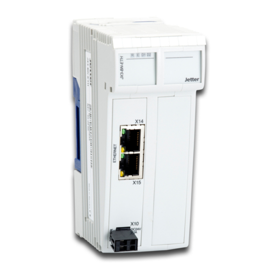
- Page 1 User Manual JX3-BN-ETH We automate your success.
- Page 2 Revisions and further development of our products are not automatically mentioned in a reviewed document. Jetter AG shall not be liable for errors in form or content, or for missing updates, as well as for damages or disadvantages resulting from such failure.
-
Page 3: Table Of Contents
Dismounting the enclosure from the backplane module ............ 19 6 Electrical connection ........................ 20 Improving the noise immunity.................... 21 Ports and interfaces ...................... 22 6.2.1 Terminal X10 - Power supply .................. 22 6.2.1.1 2-pin connector, spring-cage technology............ 22 6.2.2 Ports X14, X15 - Ethernet .................. 23 JX3-BN-ETH User Manual... - Page 4 7.6.5.1 Setting the default IP address ............... 45 7.6.5.2 Setting the IP address via configuration file .......... 45 7.6.5.3 Setting the IP address via configuration file and DIP switch ...... 46 7.6.5.4 Setting the IP address during runtime ............ 47 7.6.6 Using names for IP addresses .................. 48 JX3-BN-ETH User Manual...
- Page 5 9 Maintenance and repairs ...................... 61 Maintenance, repairs and disposal.................. 61 Storage and shipment ...................... 61 10 Service ............................ 62 10.1 Customer service ........................ 62 11 Spare parts and accessories ....................... 63 11.1 Spare parts.......................... 63 11.2 Accessories ........................... 63 11.2.1 Ethernet/EtherCAT® cable.................. 63 JX3-BN-ETH User Manual...
-
Page 6: Introduction
For information on new revisions of this document, visit the download area on our website. This document is not subject to any updating service. Start | Jetter - We automate your success. For further information refer to the following information products: ■... -
Page 7: Safety
EU directives and other country-specific regulations 2.2 Purpose 2.2.1 Intended use The Ethernet bus node JX3-BN-ETH is intended for the extension of existing con- trol systems in machines. This device is used to control machinery, such as con- veyors, production machines, and handling machines. -
Page 8: Warnings Used In This Document
Low risk CAUTION Indicates a hazardous situation which, if not avoided, could result in minor or moderate injury. Material damage NOTICE Indicates a situation which, if not avoided, could result in malfunctions or material damage. JX3-BN-ETH User Manual 8 / 64... -
Page 9: Product Description
Product description | 3 3 Product description The Ethernet bus node JX3-BN-ETH lets you set up remote I/O stations. It com- prises a JX3 bus master to which up to 16 JX3 I/O modules can be directly con- nected. The bus node enables fast cyclic communication between controllers and the remote I/O station via Ethernet. -
Page 10: Status Indication
Blinking at 1 Automatic IP configuration Blinking at 4 Reset or fatal error Boot loader is not running Blinking at 1 Automatic IP configuration Blinking at 4 Reset or fatal error Boot loader is being executed JX3-BN-ETH User Manual 10 / 64... -
Page 11: Nameplate
Serial number Certification mark Item number Hardware revision Item name 3.5 Scope of delivery Scope of delivery Item number Quantity JX3-BN-ETH 10000645 Male connector in spring-cage technology, 60870409 2-pin Terminal labels 60870411 Installation manual 60873376 JX3-BN-ETH User Manual 11 / 64... -
Page 12: Technical Specifications
Jetter AG Technical specifications | 4 4 Technical specifications This chapter contains information on electrical and mechanical data, as well as on operating data of the JX3-BN-ETH. 4.1 Dimensions 56.3 Fig. 4: Dimensions in mm 4.2 Mechanical specifications Category Description Standards... -
Page 13: Electrical Properties
JX3 system bus Logic voltage Supply voltage DC 5 V Permissible voltage range -15 % ... +10 % Additional voltage Supply voltage DC 24 V Permissible voltage range -24 % ... +20 % Tab. 6: System bus JX3-BN-ETH User Manual 13 / 64... -
Page 14: Environmental Conditions
Class B Tab. 9: Emitted interference Immunity to inter- Parameter Values Standards ference Magnetic field with mains frequency Frequency 50 Hz DIN EN 61131-2 DIN EN 61000-6-2 Magnetic field 30 A/m DIN EN 61000-4-8 JX3-BN-ETH User Manual 14 / 64... -
Page 15: Shielded Data And I/O Lines
150 Ω Criterion A Bursts Test voltage 1 kV DIN EN 61000-6-2 DIN EN 61000-6-2 tr/tn 5/50 ns DIN EN 61000-4-4 Repetition frequency 5 kHz Criterion A Tab. 12: Interference immunity - Functional earth connection JX3-BN-ETH User Manual 15 / 64... -
Page 16: Dc Power Supply Inputs And Outputs
DIN EN 61000-4-5 Surge voltages, asymmetric, line to earth Common-mode interfer- tr/th 1.2/50 µs DIN EN 61131-2 ence DIN EN 61000-6-2 1 kV DIN EN 61000-4-5 Tab. 14: Interference immunity of the DC mains inputs and outputs JX3-BN-ETH User Manual 16 / 64... -
Page 17: Mechanical Installation
Jetter AG Mechanical installation | 5 5 Mechanical installation This chapter describes how to install and replace the JX3-BN-ETH. 5.1 Installing the device on the DIN rail Functional impairment caused by unfavorable installation NOTICE ► Install the device only in vertical position on the DIN rail (DIN EN 60715). -
Page 18: Removing The Device From The Din Rail
DIN rail release latch Detail view Disconnect the system from the power supply. Remove the device from the mains. Pry the release latch (2) downwards and pull the device off the DIN rail (1). JX3-BN-ETH User Manual 18 / 64... -
Page 19: Dismounting The Enclosure From The Backplane Module
Fig. 7: Dismounting the enclosure from the backplane module DIN rail latch Detail view Disconnect the system from the power supply. Press the upper and lower latches (1) on the device simultaneously. Keep the latches pressed and pull off the enclosure. JX3-BN-ETH User Manual 19 / 64... -
Page 20: Electrical Connection
Damages to material or functional impairment NOTICE Improper implementation of the wiring harness may cause mechanical stress. ► Protect the cables from bending, twisting or chafing. ► Install strain reliefs for the connecting cables. JX3-BN-ETH User Manual 20 / 64... -
Page 21: Improving The Noise Immunity
Note 016 EMC-Compatible Installation of Electric Cabinets on our homepage. DIN rail ■ Mount the JX3-BN-ETH on a DIN rail to DIN EN 60715 with the dimensions 35 x 7.5 mm. ■ The DIN rail must be electrically conducting and grounded by either of the two ways: ■... -
Page 22: Ports And Interfaces
Ports and inter- Terminal X10 lets you connect the following interface signals: faces ■ Power supply of the JX3-BN-ETH bus node ■ Power supply for connected JX3 peripheral modules if these are not supplied by a JX3-PS1 power supply module. -
Page 23: Ports X14, X15 - Ethernet
LINK: Connection to the network exists Yellow ACT: Data transfer INFO Cables for ports X14, X15 To connect devices to ports X14 and X15, you can order cables separately as accessories [} 63]. See also 2 Ethernet/EtherCAT® cable [} 63] JX3-BN-ETH User Manual 23 / 64... -
Page 24: Commissioning
If the mode selector is in "STOP" position when the controller is powered-up, the application program will not be launched. Commissioning Carry out the following steps for commissioning the JX3-BN-ETH: ü To connect the bus node to a compatible controller, use 2 Ethernet patch ca- bles 1:1, or crossover, of the following category: Cat 5e at 10 ... -
Page 25: Led States During The Boot Process
Further information Further information on this topic can be found in the Application-oriented Manual Jetter Ethernet System Bus that can be downloaded from our homepage. 6.3.1 LED states during the boot process If the following requirements are met, the bus nodes goes through the normal boot process without errors: ■... -
Page 26: Programming
Format of numerical val- Notation Keyword Var, When, Task Commands BitClear(); Constant numerical values 100 0x100 0b100 Comment // This is a com- ment Further program processing // ... Tab. 20: JetSym sample programs JX3-BN-ETH User Manual 26 / 64... -
Page 27: Addressing Of I/O Expansion Modules
JX3 I/O module JX3-BN-ETH JX3 I/O module INFO Number of connectable expansion modules You can calculate the exact amount of connectable expansion modules by means of the JX3-sysbus_configurator_xxx_e which is available for download from our Homepage. JX3-BN-ETH User Manual 27 / 64... -
Page 28: Numbering Registers And I/Os
I/O number of the module. The I/O numbers always start with the constant prefix 10000. Digits Description value range 10000XXZZ 10000 Prefix Fig. 11: Example: I/O numbers Position of the module in the system 02 … 17 Module-specific I/O number 01 … 16 JX3-BN-ETH User Manual 28 / 64... -
Page 29: Expansion Modules Connected To An Ethernet Bus Node
Ethernet busnode and controller communicate via Ethernet system bus. When addressing expansion modules via Ethernet bus node, the Global Node Number (GNN) becomes part of the register number. System overview Ethernet TCP/IP Fig. 12: System overview JX3-BN-ETH User Manual 29 / 64... - Page 30 Up to 64 Ethernet bus nodes per controller Up to 16 JX3 I/O modules per Ethernet bus node Definition - Global The Global Node Number (GNN) is an ID number to identify Jetter devices (e.g. Node Number controllers, bus nodes) within an Ethernet network.
-
Page 31: Operating System
The JX3-BN-ETH is configured in JetSym. ü Controller and JX3-BN-ETH are connected. ü The JX3-BN-ETH is waiting in the boot loader for the OS update or the oper- ating system is running. ü The bus node is and remains switched on. -
Page 32: Operating System Update Via Ftp
Programming | 7 7.3.1.2 Operating system update via FTP An FTP client lets you transfer an OS file to the JX3-BN-ETH bus node. ü Performing the The latest OS file for the bus node has been downloaded from the Jetter update homepage. -
Page 33: File System
Jetter AG Programming | 7 7.4 File system This chapter describes the file system of the JX3-BN-ETH bus node. The file sys- tem lets you access files located on the internal flash disk. Malfunctions caused by missing or damaged system files NOTICE Careless working with system files can result in malfunctions of the device. -
Page 34: Identification
This file is not affected by formatting the flash disk. File structure The EDS file is a text file the entries of which are grouped into several sections. Example This is an example of an EDS file of a JX3-BN-ETH: ;Jetter AG Electronic Data Sheet [IDENTIFICATION] Version = 0... -
Page 35: Eds Registers
The general hardware configuration can be retrieved from the [IDENTIFICATION] [IDENTIFICATION] section. Name Example Function Version Version of this section Code Modul code for JX3-BN-ETH Name JX3-BN-ETH Corresponds to the information on the nameplate PcbRev PCB revision PcbOpt PCB option Tab. 22: Section [IDENTIFICATION]... -
Page 36: Revisions
The operating system provides several registers which can be used to read out the hardware revision or OS version of the device and its components. You will need this information when contacting the hotline of Jetter AG in case of a problem. -
Page 37: Operating System Version
7.5.2.2 Operating system version The device has special registers, the content of which are unique OS version numbers. Format of software The software version numbers of the JX3-BN-ETH are represented by 4 num- version numbers bers. Digits Description Major or main version number Fig. 15: Software version... -
Page 38: Ip Configuration
IP port number for the JetSym debugger ■ Basic port number for communication via JetIP 7.6.1 Factory settings Before the bus node JX3-BN-ETH is delivered, various parameters are set to a default value. These parameters can be changed by the user. INFO Important note A different IP address must be set at each controller and at each bus node within a JX3 station. -
Page 39: Configuration Memory
The configuration memory is located on the JX3 backplane module. Owing to this placement of the approach, configuration data will be preserved when the function module of the bus node bus node is replaced. JX3-BN-ETH User Manual 39 / 64... -
Page 40: Configuration File "Config.ini
The configuration file config.ini lets you access the configuration memory of the JX3-BN-ETH. Properties You can access this file through the file system on the JX3-BN-ETH. ■ For an FTP connection, the user must have administrator or system rights. ■... -
Page 41: Section [Hostname]
Jetter AG Programming | 7 Property Description Illegal values 1 and 0 mixed In the event of an illegal The JX3-BN-ETH resets all 4 values to their defaults. value Tab. 33: SubnetMask DefGateWay Property Description In the given example 192.168.4.1 Function IP address of the gateway to other subnets;... -
Page 42: Section [Ports]
Tab. 37: Name 7.6.3.3 Section [PORTS] In section [PORTS] the IP port numbers of data and debug servers within the JX3-BN-ETH are specified. The IP port numbers must be consistent with, for ex- ample, the port numbers set in JetSym. JetIPBase Property... -
Page 43: Configuration Registers
Jetter AG Programming | 7 Reboot the JX3-BN-ETH. ð The new configuration is active. Configuration registers let you also make changes to the IP configuration. 7.6.4 Configuration registers The configuration registers let you read out and modify IP configuration parame- ters. -
Page 44: Setting The Ip Address Of The Bus Node
Make the corresponding DIP switch settings. Reinstall the enclosure on the JX3 backplane module. ð After the restart, the bus node JX3-BN-ETH can be reached via the IP ad- dress that has been changed before. JX3-BN-ETH User Manual 44 / 64... -
Page 45: Setting The Ip Address Via Configuration File
1 2 3 4 5 6 7 8 9 10 11 12 Fig. 16: DIP switch sliders 1 ... 12 OFF 7.6.5.2 Setting the IP address via configuration file Setting the IP The config.ini file lets you set the IP address of the bus node JX3-BN-ETH. address [IP] Address = aaa.bbb.ccc.ddd Element Description Enter the IP address into this line. -
Page 46: Setting The Ip Address Via Configuration File And Dip Switch
To this end, set the 3 upper bytes of the IP address in the config.ini file, and the lower byte using the DIP switch sliders 1 … 8. Settings via con- ► Set the upper 3 bytes of the IP address of the bus node JX3-BN-ETH in the fig.ini config.ini file. [IP] Address = aaa.bbb.ccc.ddd... -
Page 47: Setting The Ip Address During Runtime
Jetter AG Programming | 7 DIP switch slider The following DIP switch settings cause the bus node JX3-BN-ETH to read out settings the IP address from the config.ini file and the DIP switch slider positions: 1 2 3 4 5 6 7 8 9 10 11 12 Fig. 18: DIP switch sliders 1 ... -
Page 48: Using Names For Ip Addresses
7.6.6 Using names for IP addresses You can also use names when specifying IP addresses from external communi- cation partners of the JX3-BN-ETH, for example, when configuring the e-mail client. The bus node resolves the names into IP addresses. A configuration file or the Domain Name System is used to resolve a name into its corresponding IP ad- dress. - Page 49 ■ File name: hosts Domain Name If a name cannot be found in the file /etc/hosts, the JX3-BN-ETH tries to resolve System (DNS) the IP address by obtaining the corresponding IP address from a DNS server. During the boot process the JX3-BN-ETH reads the IP address of the DNS server from the configuration memory.
-
Page 50: Storage Options - Overview
Programming | 7 7.7 Storage options - Overview The JX3-BN-ETH bus node features a data memory. This memory is located di- rectly in the CPU or in separate memory or I/O modules. There is, for example, volatile and non-volatile memory: ■... -
Page 51: Special Registers
Located on modules connected to the JX3 system bus ■ I/O numbers on the JX3 system bus: 100000201 ... 100001716 Memory access ■ By means of JetSym ■ By the e-mail client ■ From HMIs ■ From the application program JX3-BN-ETH User Manual 51 / 64... -
Page 52: Ethernet System Bus
Programming | 7 7.8 Ethernet system bus Controllers and modules produced by der Jetter AG offer a host of functions which can be accessed by the user via registers. The Jetter Ethernet system bus enables data exchange between controllers and bus nodes via standard Internet using publisher/subscriber mechanisms. -
Page 53: Ftp Server
The user has the option of using a command line FTP client, which comes with many PC operating systems, or graphic FTP tools. Number of possible The FTP server of the JX3-BN-ETH is able to manage up to 4 open FTP connec- connections tions simultaneously. -
Page 54: Registers - Overview
8 Registers - Overview 100600 ... Identification 100614 This register overview describes the registers of 100600 Internal version number the JX3-BN-ETH in summarized form. 100601 Module ID 100602 ... Module name (register string) Module code 100612 For identification purposes, each module has a... - Page 55 108006 "D2" LED Values 104500 Sent packets 104501 Sent bytes Flashing slowly 104502 Received packets Flashing fast 104503 Received bytes 104504 Invalid packets 104505 Discarded received packets 104506 Checksum error of the received data JX3-BN-ETH User Manual 55 / 64...
- Page 56 1001 ... 100002015 Index to module array 1008 100002016 Module array 4016 901 ... 909 ... 1001 ... 1009 ... 100002111 Register number in case of error 1008 1016 100002764 Timeout for register access [ms] JX3-BN-ETH User Manual 56 / 64...
- Page 57 1709 … 1716 2116 2208 2216 2308 4093 1709 … 1716 1801 … 1808 4042 2201 ... 2209 ... 2301 ... 2309 ... 4094 1801 … 1808 1809 … 1816 2208 2216 2308 2316 JX3-BN-ETH User Manual 57 / 64...
- Page 58 4143 1209 ... 1216 4208 501 ... 509 ... 601 ... 609 ... 4144 1301 ... 1308 4145 1309 ... 1316 4209 509 ... 601 ... 609 ... 701 ... 4146 1401 ... 1408 JX3-BN-ETH User Manual 58 / 64...
- Page 59 4279 1009 ... 1016 1101 ... 1108 4235 1809 ... 1901 ... 1909 ... 2001 ... 4280 1101 ... 1108 1109 ... 1116 1816 1908 1916 2008 4281 1109 ... 1116 1201 ... 1208 JX3-BN-ETH User Manual 59 / 64...
- Page 60 309 ... 316 4326 401 ... 408 4327 409 ... 416 4328 501 ... 508 4329 509 ... 516 4330 601 ... 608 4331 609 ... 616 4332 701 ... 708 4333 709 ... 716 JX3-BN-ETH User Manual 60 / 64...
-
Page 61: Maintenance And Repairs
In case of damaged packaging inspect the device for any visible damage, and in- form your freight forwarder and the Jetter AG of the damage caused during ship- ment. If the device is damaged or has been dropped, it is strictly forbidden to use... -
Page 62: Service
To contact them, please call our technical hotline or use the contact form on our homepage: Technical hotline | Jetter - We automate your success. You are also welcome to send an e-mail to our technical hotline: hotline@jetter.de... -
Page 63: Spare Parts And Accessories
Male connector in spring-cage technology, 2-pin 60870409 Tab. 45: Spare parts 11.2 Accessories INFO The accessories are not part of the scope of delivery. Suitable accessories can be obtained from Jetter AG. Component Item number Screwdriver 60871712 End clamp for DIN rail 60863970 Tab. 46: Accessories... - Page 64 Jetter AG Graeterstrasse 2 71642 Ludwigsburg www.jetter.de E-mail info@jetter.de Phone +49 7141 2550-0 We automate your success.