Table of Contents
Advertisement
Quick Links
Advertisement
Table of Contents

Subscribe to Our Youtube Channel
Related Manuals for Jetter JX3-PS1


Summary of Contents for Jetter JX3-PS1
- Page 1 User Manual JX3-PS1 We automate your success.
- Page 2 Revisions and further development of our products are not automatically mentioned in a reviewed document. Jetter AG shall not be liable for errors in form or content, or for missing updates, as well as for damages or disadvantages resulting from such failure.
-
Page 3: Table Of Contents
Dismounting the enclosure from the backplane module ............ 16 6 Electrical connection ........................ 17 Connector specification ...................... 17 6.1.1 Power supply terminal X10.................. 17 Functional test ........................ 17 7 Maintenance and repairs ...................... 18 Maintenance, repairs and disposal.................. 18 Storage and shipment ...................... 18 JX3-PS1 User Manual... - Page 4 Table of contents Jetter AG 8 Service ............................ 19 Customer service ........................ 19 9 Spare parts and accessories ....................... 20 Spare parts.......................... 20 Accessories ........................... 20 JX3-PS1 User Manual...
-
Page 5: Introduction
For information on new revisions of this document, visit the download area on our website. This document is not subject to any updating service. Start | Jetter - We automate your success. For further information refer to the following information products: ■... -
Page 6: Safety
Low risk CAUTION Indicates a hazardous situation which, if not avoided, could result in minor or moderate injury. Material damage NOTICE Indicates a situation which, if not avoided, could result in malfunctions or material damage. JX3-PS1 User Manual 6 / 23... -
Page 7: Product Description
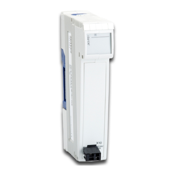
Product description | 3 3 Product description The JX3-PS1 is an expansion module and provides power supply of up to 8 ex- pansion modules. The module is required if the power supply of the bus node or controller used is not sufficient to supply all connected expansion modules. -
Page 8: Position And Amount Of Expansion Modules In The System
3.4.1 Diagnostics capabilities by means of status indication Colors and flashing patterns of the LEDs are an excellent source of information to analyze problems. Flashing pat- Color Description tern No logic circuit supply Green Logic voltage supply is OK JX3-PS1 User Manual 8 / 23... -
Page 9: Nameplate
Company logo Serial number CE marking Hardware revision Type key 3.6 Scope of delivery Scope of delivery Item number Quantity JX3-PS1 10000635 Male connector in spring-cage technology, 60870409 2-pin Terminal labels 60870411 Installation manual 60871940 JX3-PS1 User Manual 9 / 23... -
Page 10: Technical Specifications
P = 6 W max. Supplementary supply DC +24 V (+15 % … +20 %) = 1,000 mA max. P = 24 W max. Maximum power output = 24 W Tab. 2: Power supply of JX3 system bus JX3-PS1 User Manual 10 / 23... -
Page 11: Environmental Conditions
Intensity and duration 15 g for 11 ms Number and direction 3 shocks in the directions of all 3 spatial axes Degree of protection Degree of protection IP20 DIN EN 60529 Tab. 4: Mechanical specifications JX3-PS1 User Manual 11 / 23... -
Page 12: Emc Values
Standard ence Signal and control interface Frequency bands DIN EN 61000-6-3 0.15 … 0.5 MHz DC power supply inputs and outputs Limit 40 to 30 dB 0.5 … 30 MHz Limit 30 dB Class B Tab. 8: Emitted interference JX3-PS1 User Manual 12 / 23... -
Page 13: Tab. 9 Dc Power Supply Inputs And Outputs
DIN EN 61000-6-2 0.5 kV DIN EN 61000-4-5 Surge voltages, asymmetric, line to earth Common-mode interference tr/th 1.2/50 µs DIN EN 61131-2 DIN EN 61000-6-2 0.5 kV DIN EN 61000-4-5 Tab. 9: DC power supply inputs and outputs JX3-PS1 User Manual 13 / 23... -
Page 14: Mechanical Installation
Place the upper latch (2) in angled position on the DIN rail (1). Snap the lower latch of the device onto the lower edge of the DIN rail. Slide the device to its intended position. JX3-PS1 User Manual 14 / 23... -
Page 15: Removing The Expansion Module From The Din Rail
DIN rail release latch Detail view Disconnect the system from the power supply. Remove the device from the mains. Pry the release latch (2) downwards and pull the device off the DIN rail (1). JX3-PS1 User Manual 15 / 23... -
Page 16: Dismounting The Enclosure From The Backplane Module
Fig. 8: Dismounting the enclosure from the backplane module DIN rail latch Detail view Disconnect the system from the power supply. Press the upper and lower latches (1) on the device simultaneously. Keep the latches pressed and pull off the enclosure. JX3-PS1 User Manual 16 / 23... -
Page 17: Electrical Connection
The expansion modules to be supplied with power are connected to the right of the JX3-PS1 module. ► Power up the JX3 station. ð The LED R of the JX3-PS1 lights up green if the commissioning has been car- ried out correctly. JX3-PS1 User Manual 17 / 23... -
Page 18: Maintenance And Repairs
In case of damaged packaging inspect the device for any visible damage, and in- form your freight forwarder and the Jetter AG of the damage caused during ship- ment. If the device is damaged or has been dropped, it is strictly forbidden to use... -
Page 19: Service
To contact them, please call our technical hotline or use the contact form on our homepage: Technical hotline | Jetter - We automate your success. You are also welcome to send an e-mail to our technical hotline: hotline@jetter.de... -
Page 20: Spare Parts And Accessories
Inadequate accessories might cause damage to the product NOTICE Parts and equipment from other manufacturers might impede the function of the device and cause damage to the product. ● Only use accessories recommended by Jetter AG. 9.1 Spare parts Component Item no.:... - Page 21 Dimensions. All dimensions are in millimeters................ Fig. 6 Installing the expansion module on the DIN rail ..............Fig. 7 Dismounting example......................Fig. 8 Dismounting the enclosure from the backplane module ............Fig. 9 Power supply terminal X10...................... JX3-PS1 User Manual 21 / 23...
- Page 22 Tab. 5 Electrical safety ........................Tab. 6 Emitted interference ........................ Tab. 7 Immunity to interference......................Tab. 8 Emitted interference ........................ Tab. 9 DC power supply inputs and outputs..................Tab. 10 Power supply input X10 - Technical specifications ..............JX3-PS1 User Manual 22 / 23...
- Page 23 Jetter AG Graeterstrasse 2 71642 Ludwigsburg www.jetter.de E-mail info@jetter.de Phone +49 7141 2550-0 We automate your success.
Need help?
Do you have a question about the JX3-PS1 and is the answer not in the manual?
Questions and answers