Table of Contents
Advertisement
Advertisement
Table of Contents

Related Manuals for HANYOUNG NUX GR200 Series


Summary of Contents for HANYOUNG NUX GR200 Series
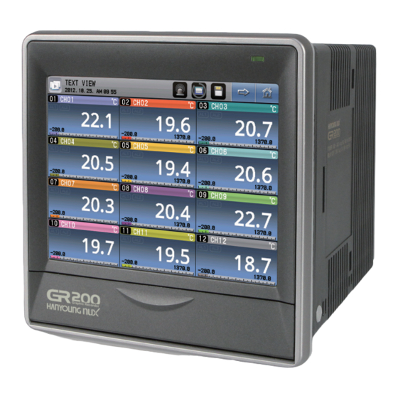
- Page 1 www.hynux.com Version 1.0 Touch-Type Graphic Recorder USER MANUAL...
- Page 2 The contents of this manual are subject to change without prior notice as a result of continuing improvements to the instrument’s performance and functions. HANYOUNG NUX contains tacit guarantee and properness for certain purposes of the manual and does not provide any guarantee which is not mentioned in the manual.
-
Page 3: Table Of Contents
Before start 1. Check the product 2. Caution for safety 3. Quality warranty Installation 1. Cautions of Installation 2. Installation method 3. Dimension & Panel cutout 4. Wiring 5. Terminal wiring diagram Operation 1. Names of each part 2. Button operation 3. -
Page 4: Before Start
Before start Thank you for purchasing the graphic recorder of HANYOUNG NUX (Model : GR200). The manual specifically explains the functions, how to install, caution and instruction of the product. Please carefully read and fully understand the manual. In addition, let the manual used by and delivered to the end-user and keep the manual in a place ready to read. -
Page 5: Caution For Safety
2. Caution for safety Alerts declared in the manual are classified to Danger, Warning and Caution by their criticality DANGER indicates an imminently hazardous situation which, if not DANGER avoided, will result in death or serious injury WARNING indicates a potentially hazardous situation which, if not WARNING avoided, could result in death or serious injury CAUTION indicates a potentially hazardous situation which, if not... -
Page 6: Installation
Installation 1. Cautions of Installation ● Please use the product with installed on the panel due to the danger of the electric shock. ● Do not install the product in the places below. • Place where a person unconsciously touches the terminal •... -
Page 7: Dimension & Panel Cutout
body clamp Attachment direction panel Fig. 1) How to install the panel The tightening torque to fix the clamp is less than 0.5 N·m. Excessive torque may distort or damage the product. Caution 3. Dimension & Panel cutout ▶ Dimension (Unit : ㎜) 173.5 164.7... -
Page 8: Wiring
4. Wiring Please cut off the power provided to the product before the wiring. Take care not to touch the terminal due to the danger of the electric shock under the power application. Danger ▶ Power wiring Please use the vinyl insulation wire with 0.9 ~ 2.0 ㎟ (KSC 3304). Much noise in the power may damage the product or malfunction. - Page 9 ▶ Input wiring Use the shield wire for the input wiring and wire with certain intervals from the power and the ground circuits. Use the RTD sensor as the 3-line sensor with the same wiring resistor. Caution ▶ Communication wiring Connect the terminating resisters (100 - 200 Ω, 0.25 W) at both ends of the communication line.
-
Page 10: Terminal Wiring Diagram
5. Terminal wiring diagram Terminal Terminal Terminal Sensor input (1) Channel 1 – 4 Digital input (2) DI3 – DI4 Digital input (2) DI1 – DI2 number number number Channel 1 DI 3 DI 1 RTD : Thermoresistor V DC : Votage DC TC : Thermocouple DI 4 DI 2... -
Page 11: Operation
Operation 1. Names of each part Front LED Display part SD card slot Power switch 2. Button operation Execution button Immediately execute the function on the button Select button Select one on the list Display and configure the number or character. The number Input box pad or keypad appears when pressed. -
Page 12: How To Operate The Number Pad
3. How to operate the number pad Fig. 6) Number pad Display the name and the configuration range of the parameter Display the configured value Register the configured value Delete the last digit of the configured value Delete all the configured values Cancel the configuration and hide the input pad. -
Page 13: Screen Block Diagram
Screen block diagram 1. Screen block diagram Power Trend screen, digital screen, bar graph screen - Save / stop the graph (internal memory, SD card) - Display the status (internal memory, SD card, alarm) - Display the list Logo screen Trend screen Digital screen Bar graph screen... -
Page 14: Operating Screen
Operating screen 1. Start and end of the record The record starts and ends from the "Trend", "Digital " or "Bar Graph" screen. Use the internal memory or the SD card for record. Start or end recording on the SD card. Start or end the recording on the internal memory. - Page 15 ▶ Record to the SD card Insert the SD card as shown in the picture to record with the SD card. <Before recognizing <After recognizing the SD card> the SD card> • The picture shows that the SD card is recognized.
-
Page 16: Printing Of List
2. Printing of list The user may print the list on the trend screen during the record. It is not possible to print the list when the record stops. It is possible to print the list during the record. Fig. 14) Trend screen - Printed list Press to show the list already recorded. -
Page 17: Alarm
3. Alarm It is possible to check the alarm on the "Trend", "Digital" or "Bar graph" screen. The alarm is configured in the "Alarm and DI ". It is the status without the alarm. It is the status with the alarm. Go to the print status page to show the activated alarm. -
Page 18: Trend Screen
4. Trend screen The screen shows the channel measurement with the graph. The graph displays the currently measured value and flows regardless of the saving. The flowing speed of the graph depends on the saving period. Go to the menu screen. Go to the digital screen. -
Page 19: Digital Screen
[ Display the error on the trend screen ] Errors occurred Display I/O connection error "I/O CONNECTION ERROR" blinks on the screen name Input connection error Display "----" AD error Display "----" Correction error Display "----" Calculation error Display "----" User BURN OUT error Display "----"... -
Page 20: Bar Graph Screen
6. Bar graph screen It is the screen which displays the channel measurement with the bar. The user may check the levels of all the channels within the displayed range under current configuration at once. However, the maximum number of displayed channels is 8 and moves each channel to check the 12 channels. -
Page 21: Configuration Screen
Configuration screen 1. Check the save log It is possible to search up to 4 hours with the period of 1 second of the measurement of lapsed time on the operating screen. Read the file to check it in the internal memory or the SD card as the graph. Fig. - Page 22 Fig. 27) View the history button - Size axis Go to the maximum value in the data. Move to the previous pixel. Move to every 10 or 20 pixels if long pressed. Move to the next pixel. Move to every 10 or 20 pixels if long pressed. Go to the minimum value in the data.
-
Page 23: Function Configuration
2. Function configuration ▶ Operating configuration Configure the data recording period. It may not be changed during saving. Configure to turn off the screen after the configured time. The power-saving function does not work if the time is configured to 0. Turn on or off buzzer sound. - Page 24 ▶ LIST Enter the message frequently used on the trend screen. Fig. 32) LIST screen [ LIST parameter ] Parameter Initial value Configuration range LIST 1 START LIST 2 STOP LIST 3 CHECK POINT LIST 4 Enter the text LIST 5 (up to 16 characters) LIST 6 LIST 7...
-
Page 25: Date / Reservation Configuration
3. Date / reservation configuration ▶ Current time Configure the current time. It may not be changed during recording. Fig. 34) Current time screen ▶ Reserved time Reserve the time when the record starts. It is impossible to reserve the time if the starting is ahead of the current time. -
Page 26: Channel Configuration
4. Channel configuration ▶ Basic configuration Select the channel. Enter the value of the range to use. It may not be changed during recording. Select the sensor type. It may not be changed during recording. Enter the input digital filter. The decimal point location is fixed if the sensor is the thermoresistor or the thermocouple. - Page 27 [ Basic channel configuration parameter ] ( nn : Channel number ) Parameter Initial value Configuration range Sensor type Refer to the table of the ranges for sensor types DCV input upper limit DCV upper limit Within the DCV sensor range DCV input lower limit DCV lower limit Within the DCV sensor range...
- Page 28 ▶ Additional configuration Enter the range to be displayed on the operating screen (trend, digital). Configure the channel name. It may not be changed during recording. Configure how to measure the data. The average, minimum and maximum calculation times of the measurement value are the same with the recording period.
- Page 29 ▶ Calculation function Decide whether to use the calculation function. It is the input window of the calculation formula. (Up to 79 characters) It is the input window of the memory formula (up to 25 characters). 4 memory variables may be configured and are commonly used in the channels.
- Page 30 Formula Caution Function Description MIN (CH1, CH4) → Minimum value of the CH1 and the CH4 MIN ( : ) Minimum value MIN (CH1 : CH4) → The minimum value between the CH1, CH2, CH3 and CH4 ASIN ( . ) (Caution 4) Inverse value of the sine ASIN (CH2) →...
-
Page 31: Alarm And Di
5. Alarm and DI ▶ Alarm configuration Configure the alarm type. Configure the operating condition of the alarm. Fig. 44) Alarm configuration screen Fig. 45) Alarm selection screen Enter the alarm configuration value. Enter the hysteresis. Configure the relay operated under the alarm. Fig. - Page 32 Enter the upper limit of the alarm operation. Enter the lower limit of the alarm operation. Fig. 47) Select the alarm 1 - Within the range / out of the range of the upper and the lower limits Enter the deviation with the channel for comparison. Enter the channel for comparison.
- Page 33 [ Alarm configuration parameter ] Parameter Initial value Configuration range Not use, upper limit, lower limit, within the range, out of the range, within the Alarm type Not use deviation among the channels, out of the deviation among the channels High point : Use range (100 %), Configuration Low point : Use range (0 %)
-
Page 34: History Management
6. History management ▶ Event The saved file name has the format of "EVT_ yymmdd.TXT". The destination folder is the "GR200_EVNT" folder in the root directory of the Reference SD card. Check by circulating a total of 80 event histories. Initialize the event history. - Page 35 ▶ Error The saved file name has the format of "ERR_ yymmdd.TXT". The destination folder is the "GR200_EVNT" folder in the root directory of Reference the SD card. Check by circulating a total of 40 error histories. Initialize the error history. (Not work during recording) Save the error history to the SD card.
- Page 36 ▶ Output status It is the screen which shows the alarm status and the external contact input/output for each channel. Fig. 53) Output status window It shows the alarm status. No alarm configuration Alarm configuration + no alarm activated Alarm configuration + alarm activated It shows the relay status.
-
Page 37: System Configuration
Fig. 55) Product specification screen [ Product specification parameter ] Parameter Initial value Configuration range Info 1 HANYOUNG NUX CO.,LTD. Enter the text (up to 30 characters) Info 2 GR200 GRAPHIC RECODER Enter the text (up to 30 characters) Info 3 www.hynux.com... - Page 38 ▶Communication configuration Select the stop bit. Select the communication protocol. Select the communication speed. Select the data length. Enter the device number. Enter the response time. Select the parity bit. Fig. 56) Communication configuration window [ Communication configuration parameter ] Parameter Initial value Configuration range...
- Page 39 • Please configure the password because the firmware upgrade required caution from the user. The initial value is "0". Please download the upgrade file from the website of "HANYOUNG NUX". Do not change the file name and take care to move the file to the GR200_FWUP directory, the root directory of the SD file. The parameters Caution are initialized after the firmware upgrade.
-
Page 40: Specifications
Specifications 1. Input specification [ Range configuration for the input types ] Input type Measurement range (°C) Measurement range (°F) Degree Pt-0 -200 ~ 640 -300 ~ 1180 Pt100 Ω Pt-1 -200.0 ~ 640.0 -300.0 ~ 1180.0 Thermoresistor Pt-2 -100.00 ~ 150.00 -300.0 ~ 1180.0 (RTD) ±0.15 % of F.S ±1digit... -
Page 41: Hardware Specification
2. Hardware specification ▶ Power input Power voltage 100 – 240 V AC Voltage fluctuation rate ±10 % Power frequency 50 – 60 ㎐ Power consumption 22 VA max Maximum internal fuse ratings 250 V AC Primary terminal* and secondary terminal** : Minimum 1500 VAC for 1 minute Primary terminal* and FG terminal : Minimum 1500 VAC for 1 minute Secondary terminal** and FG terminal : Minimum 1500 VAC for 1 minute Secondary terminal** and secondary terminal** : Minimum 500 VAC for 1 minute... -
Page 42: Display Specification
▶ Alarm output Maximum number of outputs 12 Output type Relay output Maximum ratings 5 A 250 V AC, 5 A 30 V DC Recommended ratings 3 A 250 V AC, 3 A 30 V DC 50,000 times at the maximum ratings, 100,000 times at the Relay life recommended ratings ●... - Page 43 ▶ Storage environment Ambient temperature -20 ~ 70 °C Temperature change Less than 20 °C/h Ambient humidity 5 - 95 % RH (no condensation) ▶ Impact from the ambient temperature VDC, thermocouple sensor ±0.003 % of F.S / ℃ Thermoresistor sensor ±0.03 ℃/℃...
- Page 44 MA0506E131231 HANYOUNG NUX CO., LTD. www.hynux.com 28, Gilpa-ro 71 beon-gil, Nam-gu, Incheon, Korea Tel : +82-32-876-4697 Fax : +82-32-876-4696 E-mail : overseas@hynux.com...
Need help?
Do you have a question about the GR200 Series and is the answer not in the manual?
Questions and answers