Advertisement
Quick Links
MAIN PRODUCTS
Multi Pulse Meter
- DIGITAL : Temperature Controller, Counter, Timer,Speedmeter,
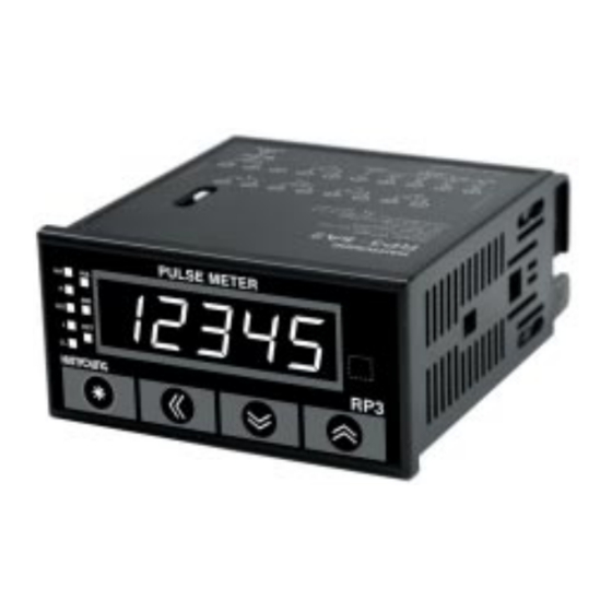
RP3
- SENSOR : Proximity Sensor/Photo Electric Sensor,
INSTRUCTION MANUAL
- ANALOG : Timer, Temperature Controller
We appreciate you for purchasing HanYoung NUX Co.,Ltd
HEAD OFFICE
product. Before using the product you have purchased,
check to make sure that it is exactly what you ordered. Then,
1381-3, Juan-Dong, Nam-Gu Incheon, Korea
please use it following the instructions below.
TEL: (82-32)876-4697 FAX : (82-32)876-4696
Safety information
Before you use, read safety precautions carefully, and use this product properly. The
precautions described in this manual contain important contents related with safety; therefore,
please follow the instructions accordingly. The precautions are composed of DANGER,
WARNING and CAUTION.
DANGER
There is a danger of occurring electric shock in the input/output terminals so please never let
your body or conductive substance is touched.
WARNING
1. This product does not contain an electric switch or fuse, so the user needs to install a
separate electric switch or fuse externally. (Fuse rating: 250V 0.5A)
2. To prevent defection or malfunction of this product, apply a proper power voltage in
accordance with the rating.
3. To prevent electric shock or malfunction of product, do not supply the power until the wiring
is completed.
4. Do not decompose, modify, revise or repair this product. This may be a cause of
malfunction, electric shock or fire.
5. Reassemble this product while the power is OFF. Otherwise, it may be a cause of
malfunction or electric shock.
6. If you use the product with methods other than specified by the manufacturer, there may be
bodily injuries or property damages.
7. There is a possibility of occurring electric shock so please use this product after installing it
onto a panel while it is operating.
CAUTION
1. The contents of this manual may be changed without prior notification.
2. Before using the product you purchased, make sure that it is exactly what you ordered.
3. Make sure that there is no damage or abnormality of the product during the delivery.
4. Do not use this product at any place with occurring corrosive (especially noxious gas or
ammonia) or flammable gas.
5. Do not use this product at any place with direct vibration or impact.
6. Do not use this product at any place with liquid, oil, medical substances, dust, salt or iron
contents. (Use at Pollution level 1 or 2)
7. Do not polish this product with substances such as alcohol or benzene. (Use neutral
detergent.)
8. Do not use this product at any place with a large inductive difficulty or occurring static
electricity or magnetic noise.
9. Do not use this product at any place with possible thermal accumulation due to direct
sunlight or heat radiation.
10. Install this product at place under 2,000m in altitude.
11. When the product gets wet, the inspection is essential because there is danger of an
electric leakage or fire.
12. If there is excessive noise from the power supply, using insulating transformer and noise
filter is recommended.
13. The noise filter must be attached to a panel which is already connected to a ground and the
wire between the filter output side and power supply terminal must be short as possible.
14. If twisting the power cables closely together then it is effective against noise.
15. Do not connect anything to the unused terminals.
16. After checking the polarity of terminal, connect wires at the correct position.
17. When this product is connected onto a panel, use a circuit breaker or switch approved with
IEC947-1 or IEC947-3.
18. Install a circuit breaker or switch at near place for convenient use.
19. Write down on a label that if the circuit breaker or switch is operating then the power will be
disconnected since the circuit breaker or switch is installed.
20. For the continuous and safe use of this product, the periodical maintenance is
recommended.
21. Some parts of this product have limited life span, and others are changed by their usage.
22. The warranty period for this product including parts is one year if this product is properly used.
Suffix Code Structure
Description
Model Name
Suffix code
RP3
Multi Pulse Meter
DIN Size: 96 x 48 x 105.6
5 digits 1 stage
100 - 240V a.c (50 - 60
)
24 - 60 V a.c / d.c
Main output
Subsidiary output
Only Display
-
Relay 3 stages Output
-
Relay 5 stages Output
-
NPN Open Collector 5 Stages Output
BCD Output
NPN Open Collector
4 - 20
Current
5 Stages Output
Output
NPN Open Collector 5
RS-
485 communication
Stages Output
NPN Open Collector 5
Low Speed Serial
Stages Output
Tachometer, Panel Meter, Recorder
Rotary Encoder, Optical Fiber Sensor,
Pressure Sensor
Ratings
100 ~ 240 V a.c (50 - 60 Hz), 24 ~ 60 V (a.c / d.c)
Power Supply
Approx. 9.5 V A (220 V a.c 60 Hz), Approx. 5 W(24 V d.c)
Power Consumption
12 V d.c
10 % 120
Voltage for Sensor
Mode F1 : FS
0.05 rdg
1 dig
Measurement
Mode F2, F3, F4, F5, F6: FS
0.01 % rdg
Accuracy
Mode F1 : 0.0003 ~ 10
Mode F2 : 0.0003 ~ 1000
Measurement Range
Mode F3, F4, F5, F6 : 0.001s-3,200 s
Mode F7, F8, F9 : 0-4 10
9
Count
Prescale
Non-Contact Input :
Max. 10
Input Signal
(ON voltage: 4.5 V - 24 V, OFF voltage: 0 - 1.0 V)
Contact Input :
Max. 30 Hz
(12 V DC, able to switch the current of 2 mA sufficiently)
Max. Displayable Digits
5 digits (0 ~ 99999)
Display Method
7 Segment (Font size(W)83 mm x (H)14 mm)
Display Cycle
0.05/0.5/1/2/4/8 sec
Hysteresis
0 ~ 9999 (applicable only for output type)
Auto Zero Time Setting Function
Display Cycle Setting Function
Time Unit Selection Function
Parameter Lock Function
Remote/Local Conversion Function
(applicable only for communication output type)
Functions
Current Output Range Selection Function
(applicable only for current output type)
Max. Min. Peak Value 10 Steps Memory Function
Start Compensation Timer Function
Electricity Failure Compensation (applicable only for F9)
Comparative Output Function (HH, H, GO, L, LL)
Transistor Output (NPN/PNP Open Collector Output):
Comparative Alarm Output
Relay Output (HH, H, GO, L, LL)
PV Transfer Output (4 - 20
d.c): Displayed Value
Output
Output Types
RS485 Communication Output : 32 channels : Displayed
Value Output, PC Setting Function)
BCD Dynamic Displayed Value Output Function
Low Speed serial Output
Above 10
(at 500 V DC mega) Between electrically
Insulation Resistance
chargeable part and non-electrically chargeable part
By noise simulator, square-shaped wave noise
Noise Immunity
(pulse width 1
)
2000 V
2000 V AC 50 Hz for 1 minute
(between AC power terminal and case,
Dielectric Strength
-
between AC terminal and measurement input terminal)
10 - 55 Hz double amplitude width 0.75 mm
Durability
in each X Y Z direction for 2 hours
10 - 55 Hz double amplitude width 0. 5 mm
Malfunction
in each X Y Z direction for 10 minutes
ME0205K071126
Durability
300 m/s
2
(approx. 30G) in each X Y Z direction for 3times
Malfunction
100 m/s
2
(approx. 10G) in each X Y Z direction for 3times
Operating Ambient
-10 ~ +60
Temperature
Storage Temperature
-20 ~ +60
Operating Ambient
35 ~ 85 % RH
Humidity
Weight
Approx. 220 g
Aspect & Panel Cutout Dimension
1 dig
Wiring Diagram
Indicator [RP3 - 5A(D)N]
Example : Wiring with
Proximate Sensor
Contact output [RP3 - 5A(D)1]
Subsidiary Output
NPN Open Collector + BCD Output [RP3-5A(D)3]
NPN Open Collector + Current Output [RP3-5A(D)4]
(without condensation)
(without condensation)
NPN Open Collector + RS-485 Communication [RP3-5A(D)5]
Unit : mm
NPN Open Collector + Low Speed Serial [RP3-5A(D)6]
Input Specification
Input Specification
The max input frequency is 10
higher than the minimum 50
At this time, it can be accurately measured if the duty rate
of the input pulse is 50 %.
Input Type Setting
Contact output [RP3 - 5A(D)2]
Caution when selecting Sensor Type
Before connecting the sensor, if the input specification is not selected
properly, the desired measure value can not be obtained.
Example of sensor type setting
Output Specification
Contact Output
Max. contact capacity : 1250 V A (a.c), 150 W (d.c)
Contact capacity : 5A 250 V a.c, 5 A 30 V d.c
Life : Electrical life - Around Fifty thousand (3A 250 V a.c)
Mechanical life - Around Ten million (Twenty times opens and closes
per minute)
Above 50
when ON/OFF time is
.
Above 50
: NPN Normal Open
: NPN Normal Close
: PNP Normal Open
: PNP Normal Close
: Contact Input Normal Open
(a Contact)
- Normal open (NPN NO)
- Normal close (NPN NC)
Advertisement

Related Manuals for HANYOUNG NUX RP3


Summary of Contents for HANYOUNG NUX RP3
- Page 1 The precautions are composed of DANGER, Unit : mm WARNING and CAUTION. 12 V d.c 10 % 120 Voltage for Sensor NPN Open Collector + Low Speed Serial [RP3-5A(D)6] DANGER Mode F1 : FS 0.05 rdg 1 dig Measurement...
-
Page 2: Operating Mode
HOLD Stop Bit : 1 Bit IN A ta(Pause Time) : ta≥20 mS Communication items RP3-5A(D)5 PC : Set value, Clear for peak value, Reset control HOLD ta(Pause Time) : ta≥20 mS RP3-5A(D)5 PC : Set value, Status value of control... - Page 3 Output Mode Function Description Parameter Table For Each Operation Mode Symbol Description : (use), (no use) Auto Zero Time (note 3) Standard Mode (note 4) Peak Hold or Reset Function The function is that if there is no input value in the time which is set as This function displays MAX value and MIN value in the comparative values.
- Page 4 : P4 Lock setting : P1 ~ P4 Lock : P2 ~ P4 Lock : Only for RP3-5A(D)4 4 ~ 20 mA Output : Only for RP3-5A(D)5 RS 485 Communication 5. Peak Display Group (Peak Value save Group) 3. Setup Group (IN/OUT...
Need help?
Do you have a question about the RP3 and is the answer not in the manual?
Questions and answers