Table of Contents
Advertisement
Advertisement
Table of Contents

Subscribe to Our Youtube Channel
Related Manuals for Siemens Sinumerik 801


Summary of Contents for Siemens Sinumerik 801
- Page 1 Start-Up 11/2005 Edition sinumerik SIEMENS SINUMERIK 801...
- Page 2 SINUMERIK 801 Document Structure User Documentation: Operation and Programming Turning Technical Documentation: Start-Up Turning User Documentation: Diagnostics Guide Turning...
- Page 3 SINUMERIK 801 SINUMERIK 801 Control System Installation and Start-Up Start-Up Built-In PLC Application Setting Up Technical Manual Services, Diagnosis & Data Saving Accessories Technical Appendix Valid for Control system SINUMERIK 801 11. 2005 Edition...
- Page 4 Other names in this publication might be trademarks whose use by a third party for his own purposes may violate the registered holder. Copyright Siemens AG 2005. All right reserved Exclusion of liability The reproduction, transmission or use of this document or its con- We have checked that the contents of this document correspond to tents is not permitted without express written authority.
- Page 5 Siemens. This product must be transported, stored and installed as intended, and maintained and operated with care to ensure that it functions correctly and safely.
-
Page 7: Table Of Contents
2.3.6 BERO input interface - X20 (BERO)…………………………………………………………………… 2-19 2.3.7 Digital inputs/outputs - X100 (DIN0) & X101 (DIN1), X200 (DOUT0) & X201 (DOUT1)… 2-20 2.3.8 Connecting cables for SINUMERIK 801 ……………………………………………………… 2-22 Installing and Starting-Up the Drive Modules …………………………………………… 2-26 2.4.1 Connecting the STEPDRIVE C/C drive modules …………... -
Page 9: Sinumerik 801 Control System
SINUMERIK 801. This documentation gives descriptions for configuring the SINUMERIK 801 with stepper drives/servo drives. System components The SINUMERIK 801 control system is a compact CNC unit. It consists of the following components: A compact CNC with an integrated 6″ LCD, full NC keys and MCP area;... -
Page 10: Control System Sinumerik
SINUMERIK 801 Control System SINUMERIK 801 system Fig.1-1 SINUMERIK 801 system overview(CNC + stepper drives + stepper motors) SINUMERIK 801 Start-Up... -
Page 11: Cnc Operator Panel
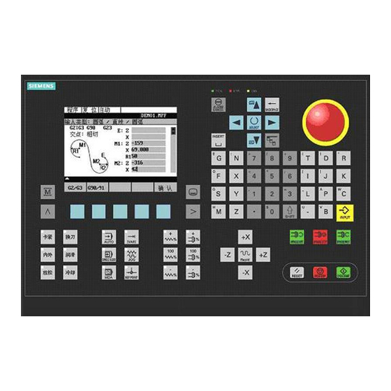
SINUMERIK 801 Control System CNC Operator Panel Layout of the CNC operator panel The SINUMERIK 801 has a compact operator panel, which can be divided into three areas as: LCD, NC keys and MCP area. NC keys MCP area Fig. 1-2 Layout of the CNC operator panel (front view) - Page 12 SINUMERIK 801 Control System Acknowledge alarm Delete key (backspace) SPACE (INSERT) Vertical menu ENTER / input key Shift key Numerical keys (with shift for Alphanumeric keys (with shift for alternative assignment) alternative assignment) … … Notice See”Operation & Programming” for the use of NC keys.
-
Page 13: Built-In Plc Application
SINUMERIK 801 Control System JOG (with LED) RESET REFERENCE POINT (with LED) NC STOP Feedrate override plus (with LED) NC START LED POK (Power OK), green Feedrate override 100% Feedrate override minus (with LED) LED ERR (Error), red Spindle override plus (with LED) -
Page 14: Position Of The Interfaces
Position of the Interfaces Interfaces of the control system are positioned in the rear of the CNC system, General see Fig. 1-3 below. Interfaces of the SINUMERIK 801 control system are shown as below: Interfaces Fig. 1-3 Position of SINUMERIK 801 interfaces Notice See Section 2.3 “Interfaces and Cables”... -
Page 15: Technical Data
SINUMERIK 801 Control System Technical Data Table 1–1 Connected load Connected load Parameter Min. Typ. Max. Unit Supply voltage 20.4 28.8 Ripple Current consumption from 24 V Power dissipation of CNC Start-up current Note: The 24V DC voltage must be generated as a functional extra-low voltage with safe electrical isolation (to EN60204-1, Section 6.4, PELV). -
Page 17: Installation And Start-Up
(e.g. PC/PG) to the control transformer, see Fig. 2-1. Control transformer Use a separate control transformer in the cabinet to supply the 24VDC power supply for CNC when Siemens stepper drives are used. Cable connections with the control transformer are shown in Fig. 2-1. SINUMERIK 801 安装调试手册... - Page 18 In order to ensure a good grounding, the cross-sectional area of PE rails shall be not less than 6mm Notice The control transformer will not be provided by Siemens. Customer may order it from other sources. Use a separate drive transformer in the cabinet to supply the 85VAC power Drive transformer supply for stepper drives.
- Page 19 Fig. 2-3 The power supply waveform If the waveform as shown in the upper right figure occurs, supply the SINUMERIK 801 in a way as indicated in the figure below and describe the system power-on sequences in the corresponding user guide for machine tools.
- Page 20 Start-Up All input signals must be level signals, i.e. level “0” (-3 ... 5VDC) and level “1” (11 ... 30VDC). Both suspended and high resistance signals are level “0”. SINUMERIK 801 Start-Up...
-
Page 21: Installing And Cabling
Stepper drives or servo drives are installed in the cabinet. The SINUMERIK 801 can be fixed in the station from the rear side of the CNC with 8 black plastic clips (each of them is equipped with one M4x16 fastening screw) specific for the control system. - Page 22 Fig.2-5 Schematic diagram for the dismounting of SINUMERIK 801 CNC Notice The control system is mounted as described above in the reverse order! Mounting dimensions See figures below for the mounting dimensions of SINUMERIK 801 CNC, STEPDRIVE C/C and step motors. Notice When AC servo drives, servo motors are used, please refer to installation instructions concerned for mounting dimensions.
- Page 23 Start-Up Mounting Dimensions SINUMERIK 801 Free space necessary for heat dissipation Holes reserved for plastic clips with screws Fig. 2-6 CNC outline dimensions SINUMERIK 801 Start-Up...
- Page 24 Screw in the lower fastening screws and tighten all screws. Vertical installation (recommended) Horizontal installation 90 (100*) 176 (180*) >50 >100 71 (73*) PE rails Changed installation angle Install with M5 screws, spacers and spring washers Without forced cooling Fig. 2-8 Mounting dimensions for stepper drives SINUMERIK 801 Start-Up...
- Page 25 100f7 10.5 239.0 15.0 90.0 13.0 ° 0AA0 6FC5 10X4 C5X2 548-0AB25- 16f6 100f7 10.5 263.5 15.0 90.0 15.0 ° 0AA0 When installing the stepper motor, its radial load shall stay within the data range listed below: SINUMERIK 801 Start-Up...
- Page 26 F r e q u e n c y [K H z ] 6 0 0 6 0 0 0 S P E E D [R P M ] Fig. 2-11 Frequency – torque characteristics of the stepper motors 2-10 SINUMERIK 801 Start-Up...
-
Page 27: Cabling
Connect the STEPDRIVE C/C drive modules, the stepper motors and the Cable overview SINUMERIK 801 control system as shown in the connection diagram 2-12. For the cables required, please refer to the diagram below. Fig. 2-12 Overview of cables 2-11... -
Page 28: Connecting With The Servo Drives (Example)
2.2.2.2 Connecting with the servo drives (example) Notice Adaptor, servo motor, servo drive and cable for connecting the adaptor to the servo drive are not included in the scope of supply of the SINUMERIK 801 control system. X-AXIS X-PLUS1 X-PLUS2... - Page 29 6FX6002-5AA52-1..0 24Vdc - power + Y_PLUS1 Y_PLUS2 Y_SIGN1 Y_SIGN2 Y_E1 Y_E1N SINUMERIK 801 CNC GOLDEN AGE AC SERVO DRIVE Fig. 2-14 Connecting with the servo drives (SINUMERIK 801+ Golden Age Adaptor + Golden Age Servo Drives) 2-13 SINUMERIK 801 Start-Up...
-
Page 30: Interfaces And Cables
Start-Up Interfaces and Cables See Fig. 2-15 for interface positions. Position of the interfaces Fig. 2-15 Rear of CNC System 2-14 SINUMERIK 801 Start-Up... -
Page 31: Power Supply For Cnc - X1
DC24 V 2.3.2 RS232 interface - X2 (RS232) When external PC/PG is required to make data communication (WINPCIN) General with the SINUMERIK 801, use RS232 plug connector (9 pin SUB-D). Table 2-3 RS232 interface X2 Name Type Pin Name Type n.c. - Page 32 Start-Up 9-Pin (801) Name 9-Pin (PC) Shield SINUMERIK 801 SINUMERIK 801 9 PIN SUB-D (fsocket) 9PIN SUB-D (socket) 9 PIN SUB-D (socket) 25 PIN SUB-D (plug) 0.1 mm 0.1 mm Fig. 2-16 Communication connector RS232(X2) RS232 terminal adapter When CNC stays ungrounded, a RS232 adapter must be used to protect RS232 connector from being broken down.
- Page 33 801 shall be no more than 15m. Notice: In order to ensure the common grounding between SINUMERIK 801 CNC and PC, use only shielded cable and make sure that the shield is connected to the metal or metal plated connector casing on both ends of the cable.
-
Page 34: Spindle Encoder Interface - X3 (Spindle)
Start-Up 2.3.3 Spindle encoder interface – X3 (SPINDLE) The spindle encoder interface (X3) of the SINUMERIK 801 is a 15-pin SUB-D General socket connector. Table 2-5 Spindle encoder interface X3 Signal Type Signal Type n.c. n.c. n.c. P5_MS n.c. P5_MS n.c. - Page 35 To provide fault-free operation, make sure that the following values are not exceeded when using preassembled interconnecting cables from SIEMENS: Table 2–6 Maximum cable lengths depending on the encoder power supply Max. Cable...
-
Page 36: Feed Drive Interface - X4 (Axis)
Start-Up 2.3.4 Feed drive interface - X4 (AXIS) The feed drive interface X4 of the SINUMERIK 801 is a 25-pin SUB-D plug General connector. Table 2-8 Feed drive interface X4 Signal Type Signal Type PULS1 PULS1_N DIR1 DIR1_N ENABLE1 ENABLE1_N... - Page 37 Table 2–9 Electrical parameters of the signal outputs for step-switching drives Parameter Unit Voltage range –10.5 10.5 Output current –3 Relay contact Table 2–10 Electrical parameters of the relay contacts Parameter Max. Unit Switching voltage Switching current Switching power Cable length: max. 35 m 2-21 SINUMERIK 801 Start-Up...
- Page 38 Track B as true and negated signal (U Max. output frequency: 500 kHz Phase offset between tracks A and B: 90º ± 30º Supply: 5 V, max. 250 mA Reset Reset key CycSta Cycle Start key CycSto Cycle Stop key 24V supply ground 2-22 SINUMERIK 801 Start-Up...
- Page 39 Start-Up Signal level (extension keys) RS422 Signal type (extension keys) Voltage input Input (24V signal) 2-23 SINUMERIK 801 Start-Up...
-
Page 40: Bero Input Interface - X20 (Bero)
When AC servo drives are used, BERO can be input as zero mark signals. However, be careful that here BERO refers to 24V pulse input. Readiness in the form of a relay contact (NO); must be integrated into the NC–READY output EMERGENCY STOP circuit. 2-24 SINUMERIK 801 Start-Up... - Page 41 Switching current Switching power Pin number of Relay NC_RDY Fig. 2-20 NC-READY output The NCREADY is an internal relay of NC. It will open when NC is not ready, and close after NC is ready for operation. 2-25 SINUMERIK 801 Start-Up...
-
Page 42: Digital Inputs/Outputs - X100 (Din0) & X101 (Din1), X200 (Dout0) & X201 (Dout1)
“0” signal, voltage range –3 ... 5 Or input open Signal delay 0 0.5 ... 3 Signal delay 1 0.5 ... 3 Notice See Section 3.2 “ Input/Output Configuration” for definitions of X100 ... X101 input signals. 2-26 SINUMERIK 801 Start-Up... - Page 43 “1” signal, nominal voltage Voltage drop max. 28.8 “1” signal, output current Simultaneity factor 0.5 per 12 outputs “0” signal, leakage current max. 2 Notice See Section 3.2 “Input/Output Configuration” for definitions of X200 ... X201 output signals. 2-27 SINUMERIK 801 Start-Up...
- Page 44 For the connections of digital inputs/outputs, see Fig. 2-22 and 2-23 below. Pin number of X100---X101 Optic-isolated Fig. 2-21 Connection of digital inputs Pin number of X200,X201 +24V +24V stabilized power supply Optic-isolated Relay Driver Driver Driver Fig. 2-22 Connection of digital outputs 2-28 SINUMERIK 801 Start-Up...
-
Page 45: Connecting Cables For Sinumerik 801
The MLFB (order no.) of the said cable is 6FX6002-5AA52-1..0 with RS422 differential signals. 25-pin SUB-D X axis connector Z axis Spindle On CNC side: + drive side: System interface X4 interface Fig. 2-23 Setpoint cable for SINUMERIK 801 2-29 SINUMERIK 801 Start-Up... -
Page 46: Connecting The Stepdrive C/C
Installing and Starting-Up the Drive Modules 2.4.1 Connecting the STEPDRIVE C/C drive modules Connect the STEPDRIVE C/C+, the stepper motors and the SINUMERIK 801 Cable overview control system as shown in Figure 2-24: Drive of axis 1 Drive of axis 2... - Page 47 On the motor side, braid the shield, provided it with a cable shoe and clamp it to the grounding screw. Pulse interface To connect the drive pulse interface to the SINUMERIK 801, use the preassembled cable, order no.6FX6 002–5AA52–1..0. On the drive side, connect the cable shield to the housing such that an electrical connection is provided via the appropriate strain relief clamp.
-
Page 48: Built-In Plc Application
(because of the bigger signal jitters). Reference point approach configuration Since the stepper motors cannot generate zero marks required by the encoder, the SINUMERIK 801 can take two configurations for approaching reference points as: double-switch mode and single-switch mode. Double-switch mode:... - Page 49 Ref. Point Fig. 2-27 BERO sampling methods Mechanical installation of the proximity switches Follow Fig. 2-28 & 2-29 to complete the mechanical installation of BERO under double-switch mode. When stepper motors is connected with a leadscrew directly: 2-33 SINUMERIK 801 Start-Up...
- Page 50 Drive current settings Use stepper drives to actuate stepper motors of different torques. When starting up the drive system, set the drive current according to the torque of the motor used. See figure below for current settings: 2-34 SINUMERIK 801 Start-Up...
- Page 51 DIR signal. Notice The DIR switch can be used to adapt the direction of rotation to the mechanics of the machine. Never actuate the switch when the drive is powered! 2-35 SINUMERIK 801 Start-Up...
-
Page 52: Connecting The Servo Drive Modules
*Select the drive transformer based on this table and the simultaneity factor of the machine coordinates (coefficient recommended: 1.0). 2.4.2 Connecting the servo drive modules Please refer to relevant technical instructions for the connection with servo drive. 2-36 SINUMERIK 801 Start-Up... -
Page 53: Built-In Plc Application
Important ! After the connection of individual components, the related functions in PLC application (emergency stop, hardware limit switch) must be commissioned first. Only after the afore-said safety functions are commissioned without error, you may start NC parameters. SINUMERIK 801 Start-Up... -
Page 54: Input/Output Configuration
Tool sensor T3 magnet, otherwise I1.3 Tool sensor T4 active high (see below for wiring diagram) I1.4 Tool sensor T5 I1.5 Tool sensor T6 I1.6 User in1 User input 1 I1.7 User in2 User input 2 24V ground SINUMERIK 801 Start-Up... - Page 55 T-CW Turret CW Q0.3 T-CCW Turret CCW Q0.4 Cooling Coolant control Q0.5 Lubrica Lubrication control Q0.6 S-Brake Spindle control Q0.7 Chuck Chuck clamping control 24V ground X201 DOUT1 Pin# Signal Input # Signal Description 24V power supply SINUMERIK 801 Start-Up...
- Page 56 User inputs/outputs a) User in1(I1.6)=0 ――>User out1(Q1.0)=0 User in1(I1.6)=1 ――>User out1(Q1.0)=1 b) User in2(I1.7)=0 ――>User out2(Q1.1)=0 User in2(I1.7)=1 ――>User out2(Q1.1)=1 c) The output values of User out3 and 4 are defined by M functions Use out3(Q1.3) User out4(Q1.2) SINUMERIK 801 Start-Up...
-
Page 57: Definition Of User Keys
Built-In PLC Application Definition of User Keys User Keys Override keys Traverse keys Fig. 3-1 User keys on MCP area SINUMERIK 801 Start-Up... - Page 58 1) Feedrate override plus key with LED The feedrate override will be increased by a set increment when pressing the key once until reaching 120% ; LED is lit when the feedrate override is more than 100%, and flashes when it reaches 120%; SINUMERIK 801 Start-Up...
- Page 59 2%, 4%, 6%, 8%, 10%, 20%, 30%, 40%, 50%, 60%, 70%, 75%, 80%, 85%, 90%, 95%, 100%, 105%, 110%, 115%, 120%. The spindle override can be adjusted by settable increments as 50%, 55%, 60%, 65%, 70%, 75%, 80%, 85%, 90%, 95%, 100%, 105%, 110%, 115%, 120%. SINUMERIK 801 Start-Up...
-
Page 60: Plc Machine Data
2) You may set MD14512[6] to desired bit to activate corresponding function. Caution PLC machine data reserved by the control system must not be changed! Definition of MD14510 Table 3-5 MD14510 MD14510 Machine Data PLC Machine Date—Integer Index 14510[0] Reserved 14510[1] Reserved SINUMERIK 801 Start-Up... - Page 61 Unit: 0.1second Range: 30~200 (3~20 seconds) Definition: Turret clamping time Unit: 0.1 second 14510[6] Range: 5~30 (0.5~3 seconds) Definition: Braking time of external brake mechanism of a contactor controlled spindle 14510[7] Unit: 0.1 second Range: 5~200 (0.5~20 seconds) SINUMERIK 801 Start-Up...
-
Page 62: Fixed Plc Alarms
Unclamping impossible while spindle run or NC start enabled in 700022 AUTO or MDA mode 700023 Programmed tool #. > Max. turret on turret# 700024 Tool not found, monitoring time up 700025 No position signals from turret 700027 Approach ref. point again after rot. monitoring 3-10 SINUMERIK 801 Start-Up... -
Page 63: Setting Up
Setting Up Setting Up NC Parameters System configuration The system configuration for SINUMERIK 801 is a turning variant, i.e.: X axis is set as the 1 axis, Z axis the 2 and spindle the 3 . Technology settings are also for turning machining. - Page 64 _NUMERA[0 … 5] parameter set No.) Note: After determining the mechanical parameters, set the axis speed. For stepper motors, the motor speed shall be determined according to its frequency-torque characteristics: motor speed = axis speed/leadscrew pitch/reduction ratio. SINUMERIK 801 Start-Up...
- Page 65 1200 speed (setpoint branch) Threshold value 36200 AX_VELO_LIMIT mm/Min X,Z 5280 velocity monitoring After the above parameters have been set, SINUMERIK 801 will automatically determine frequency when being powered 20rev./sec.×1000 pulses/rev.=20000pulses/sec., and MD31350 is set as follows: Example Designation Unit...
-
Page 66: Starting Up The Dynamic Characteristic Of The Axes
Setting Up Starting Up the Dynamic Characteristic of the Axes For SINUMERIK 801, the dynamic characteristic of the axes can be started-up General through machine data settings. Test the dynamic characteristic of the axes in JOG mode, set the max. -
Page 67: Starting Up Reference Points
Start Reference cam BERO—pulse 2) after reference cam: MD34050: REFP_SEARCH_MARKER_REVERS=1, search for BERO pulse in the same direction as the reference cam. Start Reference cam BERO—pulse Without reference cam Start BERO—pulse SINUMERIK 801 Start-Up... - Page 68 Maximum distance 34060 REFP_MAX_ X, Z to reference mark. MARKER_ Max. distance to 2 reference marks DIST for distance–coded measuring systems. Reference point 34070 REFP_VELO_ mm/Min X, Z positioning velocity Reference point 34080 REFP_MOVE X, Z distance/target SINUMERIK 801 Start-Up...
- Page 69 Setting Up point _DIST distance-coded system (with direction) Reference point 34100 REFP_SET_ X, Z 29.4 value/irrelevant to distance-coded system SINUMERIK 801 Start-Up...
-
Page 70: Software Limit Switch And Backlash Compensation
36100 POS_LIMIT_MINUS X, Z software limit switch minus 36110 POS_LIMIT_PLUS X, Z software limit switch plus Backlash compensation Test the backlash and make backlash compensations: Example Designation Unit Axis Description value 32450 BACKLASH X, Z 0.024 Backlash SINUMERIK 801 Start-Up... -
Page 71: Rotation Monitoring
The interrelations are given as below: Steps for monitoring rotation = steps per revolution of the step motor/reduction ratio Steps corresponding to follow-up error = steps × follow-up error at the max. speed/pitch of leadscrew SINUMERIK 801 Start-Up... -
Page 72: Leadscrew Error Compensation
A maximum of 64 compensation intermediate points can be set for each axis of the SINUMERIK 801. Machine tool builders may set desired number of compensation intermediate points based on actual needs. - Page 73 Edit this file on computer and change the file header into a machining program, then transfer to SINUMERIK 801; Use the Edit function of the SINUMERIK 801 to input compensation values on the operator panel directly; Start running this program (and compensation values will be input into...
- Page 74 Compensation active Notice When MD32700=1, the internal compensation value file in SINUMERIK 801 goes into the write protection automatically. To change a compensation value , first amend the compensation file and set MD32700=0 for entering the desired value into SINUMERIK 801. Finally, reset MD32700=1.
-
Page 75: Starting Up The Spindle
If the spindle has no encoder feedback, set MD30200 = 0. Input Designation Unit Axis Description value Spindle Spindle without 30200 NUM_ENCS encoder When producing a thread, configure the spindle with an encoder: Input Designation Unit Axis Description value Spindle Spindle with 30240 ENC_TYPE measuring system SINUMERIK 801 5-13 Start-Up... - Page 76 0 ... 5 36200 AX_VELO_ Spindle Speed Threshold value for LIMIT[ 0, 1 ... 5 ] velocity monitoring (control parameter set no.): 0 ... 5 31050 DRIVE_AX_ Spindle Denominator Denominator RATIO_ load gearbox (control DENUM[0,1 ... parameter 5-14 SINUMERIK 801 Start-Up...
- Page 77 N10 G91 G94 F100 S350 M4 ; thread run-in N20 G01 Z-0.5 ; K - thread lead; SF; SF – Infeed angle for N30 G33 Z-100 K2 SF=0 thread cutting ; thread run-out N40 G01 Z-0.5 N50 X50 SINUMERIK 801 5-15 Start-Up...
-
Page 79: Services, Diagnosis & Data Saving
File type has been fixed as : RS232 text Baudrate: 9600 RS232 text file screen is shown as below: Fig. 5-1 RS232 text file screen For machine tool builders, after the password assigned to them is entered, following screen appears: SINUMERIK 801 Start-Up... - Page 80 “Data…” and therefore execute corresponding data transfers. Communication tool The RS232 communication tool WinPCIN shall be loaded onto the PC (you may download corresponding tool on website at www.ad.siemens.com.cn/download/) and baudrate be set as 9600. For detailed information about baudrate setting and softeware tool version, see Fig.
- Page 81 Services, Diagnosis and Data Saving Fig.5-4 SINUMERIK 801 Start-Up...
-
Page 82: Diagnosis
Machine manufacturer may select the “Servo trace” softkey on the screen of Fig. 5-6 to branch to the corresponding “Servo trace” main screen. However, before entering this main screen, machine manufacturer password must first be input. Otherwise, system will prompt “Access Denied!” SINUMERIK 801 Start-Up... - Page 83 Initial values marker position Fig. 5-8 Meaning of the fields Press the softkey “Select Signal” to select the axis to be measured, the measuring time, threshold value, pre-trigger/post-trigger time and trigger conditions. The signal settings are fixed. SINUMERIK 801 Start-Up...
- Page 84 <SHIFT> + cursor movement by which the marker is to be moved. If a marker reaches the margin of the diagram, the next raster in horizontal or vertical direction is automatically pulled down. SINUMERIK 801 Start-Up...
- Page 85 Pressing “Zoom V +”/”Zoom V -” enables the horizontal scaling changes in the following steps: 0.01, 0.05, 0.1, 0.5, 1, 5, 10, 50, 100, 500, 1,000, 5,000 unit/ div Pressing the Auto Scaling key calculates the vertical scaling from the peak values. SINUMERIK 801 Start-Up...
-
Page 86: Data Saving
Purpose In case of any product fault and subsequent maintenance, the machine tool builder / end user is requested to fill in the Warranty Card – SINUMERIK 801 delivered in the package so that the setting data can be recovered immediately by Siemens after product has been replaced or maintained. - Page 87 34040 Creep speed (encoder no.) mm/Min 34060 Maximum distance to reference mm/Min mark 34070 Reference point positioning velocity mm/Min 34080 Reference point distance 34100 Reference point value/irrelevant for distance-coded system 35110 Maximum speed for gear change SINUMERIK 801 Start-Up...
- Page 88 [0] 36200 Threshold value for velocity mm/Min monitoring [1] 36300 Encoder limit frequency Other machine data (if necessary) 32700* note: If interpolatory compensation is used, please fill in the parameters into the following table. 5-10 SINUMERIK 801 Start-Up...
-
Page 89: Important Notice
Next time after power-on again, the password shall be input again by the machine manufacturer when necessary. Change of password by the machine manufacturer is allowed. 2) Data backup SINUMERIK 801 5-11 Start-Up... - Page 90 Be sure to make data backup after the machine has been started up and ready for delivery. Data backup includes internal data saving and external data saving. With external data saving, machine data, leadscrew error compensation data, tool data can be loaded into a PC. 5-12 SINUMERIK 801 Start-Up...
-
Page 91: Accessories
Accessories For the more convenient use of SINUMERIK 801, some accessories are also General delivered together with the control system such as fuse, emergency stop cover, etc. SINUMERIK 801 uses glass-tube fuse made by WICKMANN company, its Fuse model and specification are : 5x20mm, No.196, 4A, 250V. -
Page 92: Technical Appendix
Real values (from ±1.18 x 10 to ± 3.4 x 10 Activation conditions PO(Power On) Data active when system power on; RE(Reset) Data active whey system is reset CF(Configuration) Active when “Data Active” soft menu is enabled; IM(Immediate) Immediately active SINUMERIK 801 Start-Up... - Page 93 POWER ON (encoder no.) 0: Simulation 2: Square–wave generator, standard encoder (pulse multiplication) 3: Encoder for stepper motor _always 0, 0 BYTE 30350 SIMU_AX_VDI_OUTPUT – Output of axis signals with simulation axes POWER ON _always BOOLEAN 30600 FIX_POINT_POS SINUMERIK 801 Start-Up...
- Page 94 2147000000 DWORD 31080 DRIVE_ENC_RATIO_NUMERA – Numerator resolver gearbox (encoder no.) POWER ON _always 2147000000 DWORD 31090 JOG_INCR_WEIGHT Evaluation of an increment with INC/handwheel RESET degrees 31100 BERO_CYCLE – Steps for monitoring rotation POWER ON 2000 10000000 DWORD SINUMERIK 801 Start-Up...
- Page 95 POSCTRL_GAIN 1000/min Servo gain factor (control parameter set no.): 0 ... 5 NEW CONF _always (2,5; 2,5; 2,5; 1), ... plus DOUBLE 32260 RATED_VELO rev/min Rated motor speed (setpoint branch): 0 NEW CONF _always 3000 plus DOUBLE SINUMERIK 801 Start-Up...
- Page 96 _always 100000000 plus DOUBLE 34000 REFP_CAM_IS_ACTIVE – Axis with reference point cam RESET _always BOOLEAN 34010 REFP_CAM_DIR_IS_MINUS – Approach reference point in minus direction RESET _always BOOLEAN 34020 REFP_VELO_SEARCH_CAM mm/min, Reference point approach velocity RESET rev/min SINUMERIK 801 Start-Up...
- Page 97 _always 0., 0., 0., 0. – – DOUBLE 34110 REFP_CYCLE_NR – Sequence of axes in channel–specific referencing RESET –1: No obligatory reference point for NC Start No channel–specific reference–point approach 1–15: Sequence in channel–specific reference point approach SINUMERIK 801 Start-Up...
- Page 98 Maximum speed of gear stage (gear stage no.): 0 ... 5 CONF _always 500, 500, 1000, 2000, plus DOUBLE 4000, 8000 35140 GEAR_STEP_MIN_VELO_LIMIT rev/min Minimum speed of gearsetp (gear stage no.): 0 ... 5 NEW CONF SINUMERIK 801 Start-Up...
- Page 99 RESET _always BYTE 35400 SPIND_OSCILL_DES_VELO rev/min Reciprocation speed NEW CONF _always plus DOUBLE 35410 SPIND_OSCILL_ACCEL rev/s^2 Acceleration during reciprocating NEW CONF _always DOUBLE 35430 SPIND_OSCILL_START_DIR Starting direction during reciprocation RESET 0-2: As last direction of rotation (zero-speed SINUMERIK 801 Start-Up...
- Page 100 STANDSTILL_POS_TOL Zero–speed tolerance NEW CONF deg. plus DOUBLE 36040 STANDSTILL_DELAY_TIME Delay zero–speed monitoring NEW CONF _always plus DOUBLE 36050 CLAMP_POS_TOL Clamping tolerance NEW CONF deg. _always plus DOUBLE 36060 STANDSTILL_VELO_TOL mm/min, Maximum velocity/speed “axis/spindle stopped” NEW CONF SINUMERIK 801 Start-Up...
- Page 101 1–99, >100: Number of recognized zero mark errors during monitoring 100: Zero mark monitoring off, encoder HW monitoring off _always 0, 0 plus DWORD 36400 CONTOUR_TOL Contour monitoring tolerance band NEW CONF deg. _always DOUBLE 36500 ENC_CHANGE_TOL SINUMERIK 801 Start-Up...
- Page 102 _always plus DOUBLE 43210 SPIND_MIN_VELO_G25 rev/min Progr. spindle speed limitation G25 Immediately _always plus DOUBLE 43220 SPIND_MAX_VELO_G26 rev/min Progr. spindle speed limitation G26 Immediately _always 1000 plus DOUBLE 43230 SPIND_MAX_VELO_LIMS rev/min Spindle speed limitation with G96 Immediately SINUMERIK 801 Start-Up...
- Page 103 Technical Appendix _always plus DOUBLE 52011 STOP_CUTCOM_STORE Alarm response for TRC and feedforward stop Immediately – BOOLEAN SINUMERIK 801 Start-Up...
- Page 104 Technical Appendix SINUMERIK 801 Start-Up Techncial Manual Order No: A5E00702069 Edition: 2005.11 SINUMERIK 801 Start-Up...
- Page 105 A5E00702069...
Need help?
Do you have a question about the Sinumerik 801 and is the answer not in the manual?
Questions and answers