Sign In
Upload
Download
Add to my manuals
Delete from my manuals
Share
URL of this page:
HTML Link:
Bookmark this page
Add
Manual will be automatically added to "My Manuals"
Print this page
×
Bookmark added
×
Added to my manuals
Manuals
Brands
Firecom Manuals
Intercom System
3025R
Installation & operation manual
Firecom 3025R Installation & Operation Manual
Fire apparatus intercom remote head
Hide thumbs
1
2
3
4
5
6
7
8
9
10
page
of
10
Go
/
10
Bookmarks
Advertisement
Quick Links
Download this manual
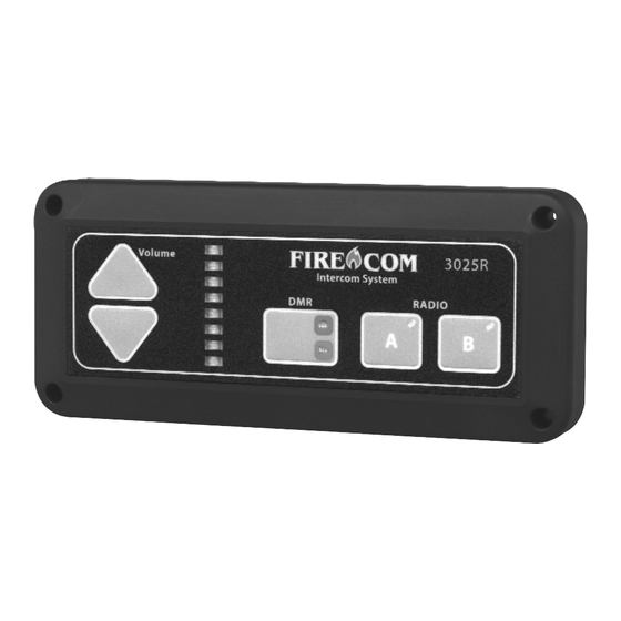
3025R•3020R•3015R•3010R
FIRE APPARATUS INTERCOM REMOTE HEAD
3025 REMOTE HEAD
I N S T A L L A T I O N & O P E R A T I O N M A N U A L
Previous
Page
Next
Page
1
2
3
4
5
Advertisement
Need help?
Do you have a question about the 3025R and is the answer not in the manual?
Ask a question
Questions and answers
Related Manuals for Firecom 3025R
Intercom System Firecom 3000C Installation & Operation Manual
Fire apparatus (40 pages)
Intercom System Firecom 3000A Installation & Operator's Manual
Fire apparatus intercom system (18 pages)
Intercom System Firecom 3010R Installation & Operation Manual
Fire apparatus intercom remote head (10 pages)
Intercom System Firecom 3010 Series Installation & Operation Manuals
(44 pages)
Intercom System Firecom 3000B Installation & Operator's Manual
Fire apparatus intercom system (18 pages)
Intercom System Firecom 4100 Operation Manual
Portable (13 pages)
Intercom System Firecom pantherC Series Operation Manual
(10 pages)
Intercom System Firecom 210 Installation & Operation Manual
Radio communication system (20 pages)
Intercom System Firecom panther CCS Operation Manual
(12 pages)
Intercom System Firecom 5000D Series Installation & Operation Manual
Digital intercoms & remote intercoms (36 pages)
Intercom System Firecom CONNECT Manual
(19 pages)
Intercom System Firecom 5000D Series Quick Reference
Digital intercom (2 pages)
This manual is also suitable for:
3020r
3015r
3010r
Print
Rename the bookmark
Delete bookmark?
Delete from my manuals?
Login
Sign In
OR
Sign in with Facebook
Sign in with Google
Upload manual
Upload from disk
Upload from URL


Need help?
Do you have a question about the 3025R and is the answer not in the manual?
Questions and answers