Table of Contents
Advertisement
Quick Links
Advertisement
Table of Contents

Subscribe to Our Youtube Channel
Related Manuals for Firecom 210


Summary of Contents for Firecom 210
- Page 1 MODEL 210 RADIO COMMUNICATION SYSTEM INSTALLATION & OPERATION MANUAL...
-
Page 3: Table Of Contents
TABLE OF CONTENTS Overview ................2 Features . -
Page 4: Overview
OVERVIEW Firecom’s 210 intercom is designed for use in rugged, demanding environments. The Firecom 210 enables clear communication between up to two occupants and a 2-way radio. It is ideal for mobile equipment with complex internal and external communication requirements and high-noise environments. When used with Firecom noise attenuating headsets, the system provides protection from hearing loss that occurs when exposed to high noise levels. -
Page 5: Features
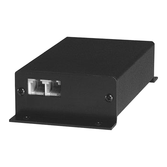
FEATURES Front View INTERCOM Modular Jacks Back View RADIO POWER Power Connector Radio Interface Jack Side View Receive Audio Adjust Transmit Audio Adjust Transmit Audio Gain Jump Intercom Audio Gain Jump Modular Jacks The modular jacks are the connection points for the CA cables leading from the intercom to the headset modules. A radio transmit priority “PR”... -
Page 6: Installation
INSTALLATION Mounting the Intercom Mount the intercom unit to a flat surface by drilling four mounting holes and installing the enclosed #6 fasteners. Mounting hole and intercom dimensions are shown below. The unit is designed for vehicle interiors and indoor use. -
Page 7: System Wiring
SYSTEM WIRING Overview Once the intercom is installed, the system is ready for wiring. Headset modules are connected to the intercom port using RJ-12 connectors and CA cables as shown in the figure below. See “CA Cable Routing” in the System Wiring section of this manual before wiring. -
Page 8: Power Connections
SYSTEM WIRING Power Connections Power is wired to the intercom using the power supply cable with in-line fuse (included). When routing the power cable, the in-line fuse should be easy to access. Warning Before making power connections, make sure the power source is turned off. Important Use a dedicated ground for the (-) power connection. -
Page 9: Daisy-Chaining Headset Modules
The CA cable from the intercom should always be plugged into the headset module on the “Firecom” label side. You will need to remove the plastic tab which covers the access hole to the auxiliary jack to add the CA cable to the next headset module. -
Page 10: Foot Switch (Optional)
Foot Switch (optional) A radio Push-to-Talk (PTT) foot switch option is available from Firecom when a headset radio PTT is not desired. The foot switch is installed to the headset module in a similar fashion as the headset module daisy-chain installation. -
Page 11: Settings
Transmit Audio Gain Jump Receive Audio Adjust Transmit Audio Adjust Several adjustments to the 210 intercom are required. When connecting to a mobile radio it will be necessary to make both transmit and receive audio adjustments. Warning These adjustments must be performed by a qualified radio technician. Failure to perform these adjustments may result in problems hearing or transmitting radio signals when using the intercom system. -
Page 12: Operation
Before testing the intercom, make sure the power supplied to the intercom is turned on. If a radio is connected to the intercom, confirm that it has power as well. To begin using the intercom, plug your Firecom headset into a headset module. For proper headset fitting instructions, as well as care and maintenance, see your headset manual. -
Page 13: Troubleshooting
TROUBLESHOOTING If the intercom system does not operate as expected, check the following items: • Check for power at the intercom and confirm that the fuse is not blown or the circuit breaker is not tripped. • Confirm that a dedicated ground is used for the intercom power and not a chassis ground. •... - Page 14 Tip: Substituting suspect components in the system may be helpful in tracking down problems. If a problem persists in a headset or intercom unit, contact Firecom for a Return Merchandise Authorization (RMA) number. Return the headset or intercom for replacement or repair.
-
Page 15: Options And Accessories
OPTIONS AND ACCESSORIES See www.firecom.com for options and accessories. SPECIFICATIONS Dimensions: L x H x W: 4.16 [106] x 2.75 [70] x 1.29 [33] inches [millimeters] Weight:: 5.9 oz (without cables) Power Requirements: Minimum: 9.5 VDC @ 83mA Maximum: 28.0 VDC @120mA Fuse: 2 amp See the headset manual for headset specifications. - Page 16 Appendix A - Wiring Diagrams PP-20 CA Cable Mobile Radio Interface Cable...
-
Page 17: Appendix B-Rj-12 Connector Assembly
Appendix B - RJ-12 Connector Assembly RJ Connector, 6 Position Plug Installation To install the RJ-12 connector plug onto the flat CA cable: 1. Using the cutter blade on the crimping tool (labeled A, in figure 1), cut the CA cable so the cut is clean and at a 90-degree angle to the side of the cable. -
Page 18: Warranty
WARRANTY Two-Year Limited Warranty to the Original Purchaser Sonetics Corporation warrants to the original purchaser of its products, that they will be free from defects in materials and workmanship, under normal and proper use, for the period of two years from date of purchase. Sonetics Corporation will repair or replace, at its option, any parts showing factory defects during this warranty period, subject to the following provisions. - Page 20 FIRECOM IS A DIVISION OF SONETICS CORPORATION 17600 SW 65th Ave, Lake Oswego, OR 97035 USA 800-527-0555 • service@firecom.com • firecom.com Copyright ©2019 Sonetics Corporation. All rights reserved. The information in this document is subject to change without notice. No part of this document may be reproduced in any form without prior written consent of Sonetics Corporation.
Need help?
Do you have a question about the 210 and is the answer not in the manual?
Questions and answers