
Subscribe to Our Youtube Channel
Related Manuals for Firecom 3000C


Summary of Contents for Firecom 3000C
-
Page 1: Intercom System
3000C FIRE APPARATUS INTERCOM SYSTEM 3000C INTERCOM I N S T A L L A T I O N & O P E R A T I O N M A N U A L REVISION D... -
Page 2: Table Of Contents
The 3000C Front Panel ........ -
Page 3: System Orientation
Figure 1 shows a typical system. Refer to this diagram for each component. INTERCOM The main control unit for the 3000C Intercom System which contains all the controls and interface circuitry for the intercom system. 2-WAY RADIO The existing 2-way radio in the apparatus. -
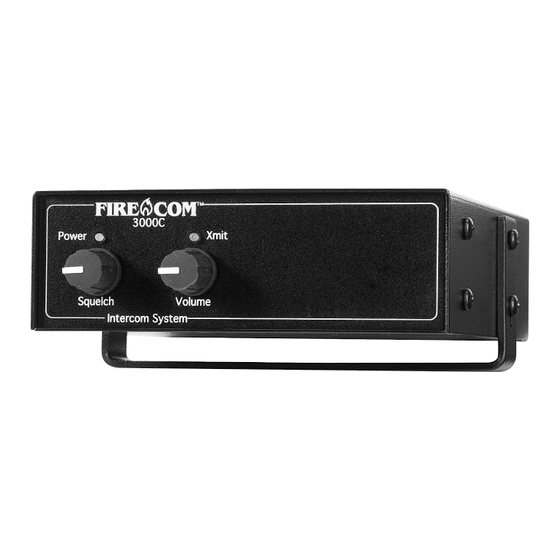
Page 4: The 3000C Front Panel
S Y S T E M O R I E N T A T I O N THE 3000C FRONT PANEL Figure 2 shows the Front Panel of the 3000C Intercom. Listed below are the different items on the Front Panel and what they control/signify. These controls are explained further in "Intercom Operation”... -
Page 5: The 3000C Rear Panel
MODULAR JACKS There are 6 modular jacks on the 3000C. These modular jacks are the connection points for the CA Cables leading from the Intercom Unit to the Headset Modules. All 6 jacks have intercom capabilities. Only the 3 jacks on the left (when viewed from the rear) are capable of transmitting on the radio (as indicated by the "TX"... -
Page 6: Installation Advisory
Careful attention should be paid to microphone ground references, wire splices, and wires that run near other high emission equipment, such as radios, antennas, antenna coax, strobes and computer cables. Contact your local Firecom Dealer if you have any questions regarding installations and wire connections. -
Page 7: Pre-Installation
System Orientation (page 1) and Installation (page 10) BEFORE installing the 3000C onto the apparatus. Taking a little time to plan the installation BEFORE installing the 3000C Intercom System, may prevent many installation errors which could result in improper system operation. -
Page 8: Headset Modules
P R E - I N S T A L L A T I O N HEADSET MODULES There are 2 different types of Headset Modules for the 3000C Intercom system (Figure 4). The HM-10 is the standard module and is designed for use inside the apparatus where it is protected from the elements. -
Page 9: Daisy-Chaining The Headset Modules
1 Radio-Transmit Headset into the Daisy-Chain at any one time. Improper Daisy-Chains in a system may result in operational problems and reduced system performance. If you have any questions regarding Daisy-Chains, contact your IMPORTANT local Firecom Dealer for more information. FIGURE 5: Daisy-Chained Label... -
Page 10: Routing The Ca Cables
Jack RADIO INTERFACE A universal Radio Interface Cable is supplied with the 3000C. This cable is a 9-wire, shield- ed cable which terminates with bare wires. These connections to the radio should be per- formed by a qualified radio technician. -
Page 11: Intercom Adjustments
MUST be performed for proper operation of the system. These adjustments are outlined on page 14 in this manual. These adjustments to the intercom MUST be performed by a qualified Radio Technician to ensure proper operation of the 2-way radio and 3000C Intercom System. IMPORTANT OPTIONAL FOOT SWITCH The optional Foot Switch (FS-1) is used in situations where the user cannot, or does not wish to, use the headset-mounted PTT. -
Page 12: Installation
I N S T A L L A T I O N Before installing the Firecom Series 3000C Intercom, make sure you have read AND UNDERSTOOD the ENTIRE installation procedure. You should also read the sections on IMPORTANT Pre-Installation (page 5) and System Orientation (page 1). If any item in the Installation... -
Page 13: Installing The Ca Cables
Jack in the HM-10 as shown in Figure 11. If the CA Cable is going from the Headset Module to the Intercom, it MUST be inserted into the Modular Jack on the same side of the HM-10 as the “Firecom“ IMPORTANT label. -
Page 14: Power & Ground Connections
21. Connect the red wire (from pin 2) to one end of the supplied in-line fuse holder. 22. Connect the other end of the fuse holder to the vehicles switched +12 VDC. The 3000C Series Intercom System is installed and ready for connection to the radio. FIGURE 14:... -
Page 15: Radio Connections
I N S T A L L A T I O N RADIO CONNECTIONS To ensure proper operation, the connection to the radio should be performed by a qualified Radio Technician. IMPORTANT 23. If you are using a radio-specific interface cable, follow the directions included with the interface cable, then proceed with step #26 in this installation procedure. -
Page 16: Intercom Adjustments
IMPORTANT radio signals when using the Intercom System. FIGURE 16: RECEIVE AUDIO ADJUSTMENT: The 3000C Adjustments 26. Turn the 2-way radio on, and adjust the radio volume to the normal volume level for use WITHOUT THE INTERCOM INSTALLED. Range Switch Assembly 27. -
Page 17: Auxiliary Input & Output
AUXILIARY INPUT & OUTPUT FIGURE 17: On the back of the 3000C, there are 2 jacks labeled "Aux In" and "Aux Out" (Figure 17). 3000C Rear Panel These jacks are 3.5mm mono (2 conductor) jacks. The auxiliary input signal will be mixed with the radio and the intercom audio. -
Page 18: System Test
S Y S T E M T E S T This procedure tests all functions of the 3000C Intercom System and should be used to test the system for proper operation after installation. In the event of a system failure, it may also be used to help identify and isolate the exact symptoms before troubleshooting a problem and to test the system after repair work has been performed. - Page 19 S Y S T E M T E S T TEST THE INTERCOM-ONLY HEADSETS 17. Connect an Intercom-Only Headset to an intercom-only station. 18. Adjust the headset for a comfortable fit and microphone position. 19. Press the black Push-To-Talk (PTT) button on the headset and verify intercom operation by listening to your own voice.
-
Page 20: Intercom Operation
Driver, Officer and Pump Panel positions. There are 2 models of Radio Transmit Headsets available for use with the 3000C Intercom System: the UH-10 and the FH-10. There is a RED Push-To-Talk (PTT) button located on... - Page 21 IMPORTANT communication. LEFT & RIGHT DRESS The Firecom headsets may be adjusted so the mic is on the right side (right dress) or left side (left dress). • Over-The-Head (FH) style headsets: Rotate the Mic Boom ONLY in an upward direction (Figure 19).
-
Page 22: Intercom Controls
I N T E R C O M O P E R A T I O N INTERCOM CONTROLS The 3000C Intercom Unit has two controls on the front panel which affect the intercom operation (Figure 22). VOLUME: The Volume Control is the master control for overall volume of the 3000C Intercom System. -
Page 23: Modular Plug Installation
M O D U L A R P L U G I N S T A L L A T I O N This section describes the installation of the RJ-12 Modular Plugs onto the flat CA Cable. Using the cutter blade on the crimping tool (labeled “A” in Figure 26), cut the flat CA Cable so the cut is clean and 90 degrees to the sides of the cable. -
Page 24: Service Information
S E R V I C E I N F O R M A T I O N The Firecom 3000C Intercom System, when installed properly, and adjusted according to specifications, will perform reliably and offer you the finest in hearing protection and enhanced communication. - Page 25 S E R V I C E I N F O R M A T I O N MODULAR CONNECTOR: The six conductor plugs on the ends of the CA Cables. These connectors plug into the Headset Modules and the Intercom Unit. Also referred to as a RJ-12 Modular Connector.
- Page 26 S E R V I C E I N F O R M A T I O N ALTERNATOR WHINE & OTHER DISTRACTING NOISES Because of the level of ambient noise present with the apparatus motor running, alternator whine and other noises may not be noticed in the communications systems until an inter- com is added.
- Page 27 Plug the headset into another good headset location. • If the headset fails to perform properly in the new location, the headset is faulty. Contact Firecom for a Return Authorization to return the headset for repair.
- Page 28 S E R V I C E I N F O R M A T I O N Unplug the CA Cable from the intercom unit and exchange intercom ports with a known good headset location. • If the headset location works properly, check the intercom port for bent or stuck pins which can be straightened.
-
Page 29: Advanced Troubleshooting
Make sure you read and understand THE ENTIRE procedure BEFORE attempting any of the troubleshooting steps in this section. If there are questions regarding this information, contact your local Firecom Dealer for more information BEFORE proceeding with the troubleshooting steps. - Page 30 Check to see if the headset is a model UH-10S headset. The UH-10S has 1 "slotted" ear dome without a speaker in it. This is normal operation for a UH-10S. The headset is faulty. Contact Firecom for a Return Authorization to return the headset for repair.
- Page 31 "Troubleshooting a Headset Location" (Page 25). If the headset location checks good, the fault must lie in the Intercom Unit. Contact Firecom for a Return Authorization to return the Intercom Unit for repair. G) THERE IS A LOUD SQUEAL IN THE INTERCOM SYSTEM WHEN THE INTERCOM VOLUME IS TURNED UP Check for an open mic too near the speakers of a headset.
- Page 32 A D V A N C E D T R O U B L E S H O O T I N G If no fault can be found, then the fault must lie in the Intercom Unit. Contact Firecom for a Return Authorization to return the Intercom Unit for repair. J) THE RADIO DOESN'T KEY Check the affected headset location for faulty connections or components.
- Page 33 N) INTERCOM VOLUME CONTROL HAS NO EFFECT Contact Firecom for a Return Authorization to return the Intercom Unit for repair. O) INTERCOM SQUELCH CONTROL HAS NO EFFECT Contact Firecom for a Return Authorization to return the Intercom Unit for repair.
-
Page 34: Wiring
W I R I N G D I A G R A M S & S C H E M A T I C S 5 Conductor Plug FIGURE 27: 5 Conductor Jack HM-10 Wiring NOT USED Pin 1 Pin 6 SPEAKER HI SPEAKER LO MIC HI... -
Page 35: Wiring
W I R I N G D I A G R A M S & S C H E M A T I C S FIGURE 28: PP-20 Wiring 5 Conductor Jack w/GND Ring* Not Connected SPEAKER HIGH SPEAKER LO MIC HIGH MIC LOW FIGURE 29:... -
Page 36: Specifications
S P E C I F I C A T I O N S HEADSETS: Sensitivity: ....104 dB re .0002 microbar @ 1000 Hz, 1 mW Frequency Response: . -
Page 37: Options & Accessories
O P T I O N S & A C C E S S O R I E S HEADSETS: All Firecom Headsets for the 3000C Intercom System are equipped with a noise-canceling electret condenser microphone on a solid, flexible boom, Glove Rugged™ plug, volume control, adjustable headstrap/headband and liquid foam ear seals. - Page 38 Part Number: 108-0025-00 HEADSET HANGER HOOKS: Rubber-coated, steel headset hanger hook. Part Number: 108-0676-00 HANDHELD RADIO INTERFACE: Works with all Firecom headsets. Contact your local Firecom Dealer for specific information regarding your particular handheld radios. HS-1: System Selector Switch. Part Number: 108-0677-10 MIC MUFFS (DOZEN): Replacement mic muffs with O-rings, sold only by the dozen.
-
Page 39: Warranty
No suit for breach of express or implied warranty may be brought after two years from date of purchase. FIRECOM is a division of Sonetics Corporation...
Need help?
Do you have a question about the 3000C and is the answer not in the manual?
Questions and answers