Sign In
Upload
Download
Table of Contents
Contents
Add to my manuals
Delete from my manuals
Share
URL of this page:
HTML Link:
Bookmark this page
Add
Manual will be automatically added to "My Manuals"
Print this page
×
Bookmark added
×
Added to my manuals
Manuals
Brands
Firecom Manuals
Intercom System
5000D Series
Installation & operation manual
Firecom 5000D Series Installation & Operation Manual
Digital intercoms & remote intercoms
Hide thumbs
Also See for 5000D Series
:
Quick reference
(2 pages)
1
2
Table Of Contents
3
4
5
6
7
8
9
10
11
12
13
14
15
16
17
18
19
20
21
22
23
24
25
26
27
28
29
30
31
32
33
34
35
36
page
of
36
Go
/
36
Contents
Table of Contents
Troubleshooting
Bookmarks
Table of Contents
Table of Contents
Digital Intercoms Overview
System Orientation
System Orientation
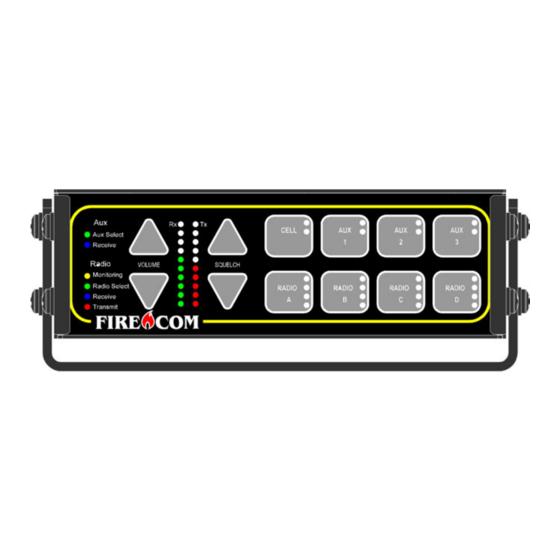
5000D Series Front Panel Controls
5000D Series Rear Panel
Pre-Installation
Installation
System Test
Intercom Operation
Programming Input and Output Device Gain
Modular Plug Installation
Troubleshooting
Advanced Troubleshooting
Wiring Diagram & Schematics
Wiring Diagram & Schematics
Specifications
Options & Accessories
Firecom Standard Limited Warranty
Advertisement
Quick Links
1
Table of Contents
2
Installation
3
Programming Input and Output Device Gain
4
Troubleshooting
5
Advanced Troubleshooting
6
Wiring Diagram & Schematics
Download this manual
5000D Series Digital Intercoms
5100D, 5200D, 5300D, 5400D Series Digital Intercoms & Remote Intercoms
Installation & Operation Manual
1
Table of
Contents
Previous
Page
Next
Page
1
2
3
4
5
Advertisement
Table of Contents
Troubleshooting
TROUBLESHOOTING
24
ADVANCED TROUBLESHOOTING
26
Need help?
Do you have a question about the 5000D Series and is the answer not in the manual?
Ask a question
Questions and answers
Subscribe to Our Youtube Channel
Related Manuals for Firecom 5000D Series
Intercom System Firecom 5000D Series Quick Reference
Digital intercom (2 pages)
Intercom System Firecom 5100D Series Installation & Operation Manual
Digital intercoms & remote intercoms (36 pages)
Intercom System Firecom 5200D Series Installation & Operation Manual
Digital intercoms & remote intercoms (36 pages)
Intercom System Firecom 4100 Operation Manual
Portable (13 pages)
Intercom System Firecom 3000C Installation & Operation Manual
Fire apparatus (40 pages)
Intercom System Firecom 3000A Installation & Operator's Manual
Fire apparatus intercom system (18 pages)
Intercom System Firecom 3025R Installation & Operation Manual
Fire apparatus intercom remote head (10 pages)
Intercom System Firecom pantherC Series Operation Manual
(10 pages)
Intercom System Firecom 210 Installation & Operation Manual
Radio communication system (20 pages)
Intercom System Firecom 3010 Series Installation & Operation Manuals
(44 pages)
Intercom System Firecom panther CCS Operation Manual
(12 pages)
Intercom System Firecom CONNECT Manual
(19 pages)
Intercom System Firecom 3000B Installation & Operator's Manual
Fire apparatus intercom system (18 pages)
This manual is also suitable for:
5400d series
5200d series
5100d series
5300d series
Table of Contents
Print
Rename the bookmark
Delete bookmark?
Delete from my manuals?
Login
Sign In
OR
Sign in with Facebook
Sign in with Google
Upload manual
Upload from disk
Upload from URL


Need help?
Do you have a question about the 5000D Series and is the answer not in the manual?
Questions and answers