BMW I Wallbox Installation Instructions Manual
Hide thumbs
Also See for I Wallbox:
- Installation instructions manual (44 pages) ,
- Installation instructions manual (56 pages) ,
- Instructions for use manual (24 pages)
Table of Contents
Advertisement
Advertisement
Table of Contents

Related Manuals for BMW I Wallbox


Summary of Contents for BMW I Wallbox
- Page 1 BMW i The Ultimate Driving Machine BMW i Wallbox Installation instructions...
- Page 3 BMW i Wallbox Installation instructions...
-
Page 5: Table Of Contents
BMW i Wallbox Installation instructions Content NOTES Safety instructions Intended use About this manual Scope of delivery Guarantee OVERVIEW Displays and controls REQUIREMENTS General requirements for selecting a location Requirements for electrical connection INSTALLATION Prerequisites for installation Recommended installation positions... - Page 6 Technical data Standards and guidelines DISPOSAL SOFTWARE UPDATE PRODUCT INFORMATION PAGE INDEX...
- Page 7 Munich, Germany www.bmw.com Original installation instructions Copyright ©2016 BMW AG Munich This documentation contains information protected by copyright. All rights are reserved, especially the right to copying and distribution. No part of the documentation may be reproduced or processed using electronic systems, copied, or distributed in any form whatsoever (by photocopying, scanning, or any other process) without the written agreement of Bayerische Motorenwerke Aktiengesellschaft.
- Page 8 This warning draws attention to the potential consequences of contact with electrostatically sensitive components. Note Refers to procedures which have no danger of creating injury. Note Your BMW dealer will be happy to support you in finding a qualified installation partner.
-
Page 9: Notes
NOTES Safety instructions Read the safety instructions carefully and examine the device, so that you become familiar with it, before you attempt to install operate or maintain it. WARNING Electrical danger! Installation, commissioning, maintenance and retrofitting of the Wallbox must be carried out by appropriately trained, qualified, and authorized electricians , who bear full responsibility for complying with the applicable standards and installation regulations. - Page 10 WARNING Grounding regulations This product must be grounded. If a malfunction or outage occurs, then grounding provides the electrical current with a path of least resistance, in order to reduce the risk of an electric shock. This product is equipped with a cable which has a device grounding conductor and a grounding plug.
-
Page 11: Intended Use
About this manual This manual and the functions described are valid for devices of the type: BMW i Wallbox This manual is intended exclusively for qualified personnel. These are persons who, on the basis of their specialist training, knowledge, and experience, as well as knowledge of the applicable standards, can assess the tasks assigned to them and recognize possible dangers. -
Page 12: Scope Of Delivery
Defects or damage caused because the product was not used as per the requirements in the BMW i Wallbox operating instructions. Costs and damage arising from repairs which were not carried out by a BMW i sales outlet or by a specialized electrician authorized by a contracted service workshop. -
Page 13: Overview
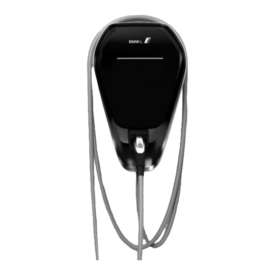
OVERVIEW Displays and controls Functions: Charging of electric or plug-in hybrid vehicles 1 Status LED 2 Holder for charger cable connector 3 Charger cable connector... -
Page 14: Requirements
REQUIREMENTS General requirements for selecting a location The Wallbox was designed for indoor and outdoor use. It is therefore necessary to make arrangements for the installation location and protection of the device. Take into account the locally applicable requirements for electrical installations, measures for fire prevention, and accident prevention regulations, as well as escape routes at the location. -
Page 15: Requirements For Electrical Connection
Requirements for electrical connection As delivered, the maximum charging current for the Wallbox is set to 32 A. Pre-installed connection cable As delivered, the Wallbox is provided with a pre-installed connection cable with a NEMA 6-50p plug which can be inserted into an appropriate socket. The following safety measure must be installed: Branch circuit breaker: max. -
Page 16: Installation
Recommended installation positions When selecting the installation position, please take into account the position of the charging connection on your vehicle and the usual direction of parking. Examples: BMW i3 BMW PHEV 1 Recommended installation position 2 Alternative installation position... -
Page 17: Necessary Installation Space
Necessary installation space The installation space specified below (hatched area) ensures convenient installation and operation of the Wallbox. If several Wallboxes are installed next to each other, then a separation of at least 200 mm (8") must be maintained between the Wallboxes. Note The installation height must be complied with, in order to fulfill the requirements for indoor and outdoor use. -
Page 18: Removing The Casing Cover
Removing the casing cover 1. On the underside of the Wallbox, push the two locking mechanisms 1 of the casing cover upwards. The casing cover should spring outwards a little at the bottom. 2. On the underside, swing the casing cover forwards a little 2. -
Page 19: Removing The Connector Panel Cover
Removing the connector panel cover Note It is necessary to remove the connector panel cover only if the setting of the DIP switches needs to be changed, or if the Wallbox is to be permanently connected to the power network. 1. -
Page 20: Installing The Wallbox
Installing the Wallbox The attachment material supplied is suitable for concrete, tiling, and wood (without the use of plugs). If the substructure is not one of the above, then a suitable type of attachment must be selected. Note If the substructure is not one of the above, then the attachment materials must be provided by the customer. - Page 21 Installation on cavity walls For installation on cavity walls, at least two attachment screws, e.g. 1 and 2, must be attached to one of the wall's supporting elements. For the other attachment screws, special cavity wall plugs must be used. Note When installing on a cavity wall, you must ensure specifically that the structure has...
-
Page 22: Connecting The Supply Line
Connecting the supply line As supplied, the Wallbox is equipped with a pre- installed connection cable (1). This can be connected into an appropriate socket, using a NEMA 6-50p plug. If required, the supply line can also be converted by a specialist into a permanent connection to an existing domestic installation, but the nationally applicable regulations must be complied with. -
Page 23: Electrics
ELECTRICS Connection overview (with open connector panel cover) DSW1 DIP switch for configuration X3 Diagnostics connection, RJ45 DSW2 DIP switch X4 Ethernet1 connection, LSA+ terminals T1 Service button X5 USB connection LED Status LED (internal) Shd Shield connection for Ethernet1 connection terminals X2 RS485 connection ATTENTION... -
Page 24: Settings
SETTINGS DIP switch settings Note Changes to the DIP switch settings take effect only after a restart of the Wallbox! To do this, press the Service button for 1 second, or switch the supply voltage off and back on. Note Switches which are not described here must be left in the OFF position. - Page 25 Maximum charging current (DSW1) The following DIP switches can be used only to set a maximum value for the charging current which is less than or equal to the operating current defined on the type plate. Current DIP switch Illustration DSW1.6 DSW1.7 DSW1.8...
-
Page 26: Commissioning
COMMISSIONING General commissioning process Switch on the supply voltage. 15-20 seconds after the self-test, the status LED (LED strip) must light up blue. Carry out the prescribed initial testing as per locally applicable guidelines and laws. Install the casing cover, see section Installing the casing cover. - Page 27 Casing marking 1. Tighten the four bolts until the casing markings at right and left on the connector panel cover close flush with the casing. 2. The connector panel cover must be correctly sealed by the casing. For self-tapping bolts, an increased torque application is required: 2.58 ft·lb.
-
Page 28: Installing The Casing Cover
Installing the casing cover Note This cover is not essential for the safe operation of the Wallbox. Attaching the casing cover 1. Attach the casing cover at the top, and ensure that the hooks of the casing cover are correctly inserted 1. -
Page 29: Miscellaneous
MISCELLANEOUS Dimensions Dimensions in millimeters... -
Page 30: Technical Data
Technical data Electrical data Cable feed: Surface or flush-mounted Connection cross-section: As per the branch circuit breaker Supply terminals: Connection line: - AWG (min.-max.): 24 – 6 Temperature rating for supply terminals: 105 °C (221 °F) Rated current (configurable connection values): 10 A, 13 A, 16 A, 20 A, 25 A, or 32 A 1-phase (3 lines) Mains voltage:... -
Page 31: Standards And Guidelines
Ambient conditions Operating temperature range -30 °C to +50 °C (-22 °F to 122 °F) without direct sunlight Temperature behavior: This is not a safety device, merely an operating function. The specified operating temperature range must be complied with. Within the specified operating temperature ranges, the device provides the charging current continuously. - Page 32 Recognized standards UL 2594 Electric vehicle supply equipment CSA C22.2 No. 280 NMX-J-677-ANCE UL 2231-1 Personnel protection systems for electric vehicle CSA C22.2 No. 281.1 (EV) NMX-J-668/1-ANCE Supply circuits: General requirements UL 2231-2 Personnel protection systems for electric vehicle CSA C22.2 No.281.2 (EV) NMX-J-668/2-ANCE Supply circuits: Particular requirements for...
-
Page 33: Disposal
DISPOSAL After correctly decommissioning the device, please have the device disposed of by Service or else in compliance with all currently applicable disposal regulations. Disposal information The symbol of the "crossed-out" waste bin means that electrical and electronic devices, including accessories, must be disposed of separately from general household garbage. -
Page 34: Software Update
“Configuration” section of the operating manual. The software can also be updated using the USB connection inside the device. Detailed instructions for the recommended procedure can be found on the BMW i Service page for charging products (https://charging.bmwgroup.com/web/wbdoc/). The latest software can be downloaded from the Internet at https://charging.bmwgroup.com/web/wbdoc/. -
Page 35: Product Information
PRODUCT INFORMATION PAGE This product is UL-certified. It complies with the applicable UL, CSA, and ANCE standards for North America, Canada, and Mexico. Further information at https://charging.bmwgroup.com/web/wbdoc/. FCC INFORMATION This device complies with part 15 of the FCC Rules. Operation is subject to the following two conditions: (1) This device may not cause harmful interference, and (2) this device must accept any interference received, including interference that may cause... - Page 36 This product is NOM-certified. MEXICO Operation is subject to the following two conditions: (1) This device may not cause harmful interference, and (2) this device must accept any interference received, including interference that may cause undesired operation.
-
Page 37: Index
INDEX About this manual................................. 11 Attaching the Wallbox..............................21 BMW i Wallbox overview............................13 Commissioning................................26 Connecting the supply line............................22 Connection overview (with open connector panel cover)................. 23 DIP switch settings............................... 24 Disposal.................................... 33 General requirements for selecting a location...................... 14 Imprint.................................... - Page 38 Technical data................................30...
- Page 40 Mehr über BMW www.bmw.de www.bmw.com Freude am Fahren 102469 IA BMW i Wallbox UL...
Need help?
Do you have a question about the I Wallbox and is the answer not in the manual?
Questions and answers