Table of Contents
Advertisement
Quick Links
Air-Conditioners
PMH-P 1, 1.6, 2BA
PUH-P · GAA
INSTALLATION MANUAL
E
For safe and correct use, please read this installation manual thoroughly before installing the air-conditioner unit.
INSTALLATIONSHANDBUCH
D
Zum sicheren und ordnungsgemäßen Gebrauch der Klimaanlage das Installationshandbuch gründlich durchlesen.
MANUEL D'INSTALLATION
F
Veuillez lire le manuel d'installation en entier avant d'installer ce climatiseur pour éviter tout accident et vous assurer d'une utilisation correcte.
INSTALLATIEHANDLEIDING
NL
Voor een veilig en juist gebruik moet u deze installatiehandleiding grondig doorlezen voordat u de airconditioner installeert.
MANUALE DI INSTALLAZIONE
I
Per un uso sicuro e corretto, leggere attentamente questo manuale di installazione prima di installare il condizionatore d'aria.
MANUAL DE INSTALACIÓN
ES
Para un uso seguro y correcto, lea detalladamente este manual de instalación antes de montar la unidad de aire acondicionado.
MANUAL DE INSTALAÇÃO
PR
Para segurança e utilização correctas, leia atentamente este manual de instalação antes de instalar a unidade de ar condicionado.
E°XEIPI¢IO O¢H°IøN E°KATA™TA™H™
GR
°È· ·ÛÊ¿ÏÂÈ· Î·È ÛˆÛÙ‹ ¯Ú‹ÛË, ·Ú·Î·Ï›ÛÙ ‰È·‚¿ÛÂÙ ÚÔÛ¯ÙÈο ·˘Ùfi ÙÔ ÂÁ¯ÂÈÚ›‰ÈÔ ÂÁηٿÛÙ·Û˘ ÚÈÓ ·Ú¯›ÛÂÙ ÙËÓ ÂÁηٿÛÙ·ÛË Ù˘ ÌÔÓ¿‰·˜ ÎÏÈÌ·ÙÈÛÌÔ‡.
MONTAJ ELK‹TABI
TR
Emniyetli ve do¤ru biçimde nas›l kullan›laca¤›n› ö¤renmek için lütfen klima cihaz›n› monte etmeden önce bu elkitab›n› dikkatle okuyunuz.
РУКОВОДСТВО ПО УСТАНОВКЕ
RU
Для осторожного и правильного использования прибора необходимо тщательно ознакомиться с данным руководством по установке до выполнения установки кондиционера.
FOR INSTALLER
FÜR INSTALLATEURE
POUR L'INSTALLATEUR
VOOR DE INSTALLATEUR
PER L'INSTALLATORE
PARA EL INSTALADOR
PARA O INSTALADOR
°π∞ ∞À∆√¡ ¶√À ∫∞¡∂π
∆∏¡ ∂°∫∞∆∞™∆∞™∏
MONTÖR ‹Ç‹N
ДЛЯ УСТАНОВИТЕЛЯ
ON/OFF
TEMP.
Advertisement
Table of Contents

Related Manuals for Mitsubishi Electric Mr. SLIM PMH-P 1BA Series


Summary of Contents for Mitsubishi Electric Mr. SLIM PMH-P 1BA Series
- Page 1 Air-Conditioners PMH-P 1, 1.6, 2BA PUH-P · GAA FOR INSTALLER FÜR INSTALLATEURE POUR L’INSTALLATEUR VOOR DE INSTALLATEUR PER L’INSTALLATORE PARA EL INSTALADOR PARA O INSTALADOR °π∞ ∞À∆√¡ ¶√À ∫∞¡∂π ∆∏¡ ∂°∫∞∆∞™∆∞™∏ MONTÖR ‹Ç‹N ДЛЯ УСТАНОВИТЕЛЯ ON/OFF TEMP. INSTALLATION MANUAL For safe and correct use, please read this installation manual thoroughly before installing the air-conditioner unit. INSTALLATIONSHANDBUCH Zum sicheren und ordnungsgemäßen Gebrauch der Klimaanlage das Installationshandbuch gründlich durchlesen.
-
Page 2: Table Of Contents
Contents Contents Inhaltsverzeichnis Index Inhoud Indice 1. Safety precautions ................... 4 2. Installation location ................12 3. Installing the indoor unit ................. 16 4. Installing the outdoor unit ............... 34 5. Installing the refrigerant piping ............... 38 6. Drainage piping work ................52 7. - Page 3 Contenido Índice ¶ÂÚȯfiÌÂÓ· ‹çindekiler 中 Содержание 1. Medidas de Seguridad ................5 1. Precauções de Segurança ..............5 2. Lugar en que se instalará ..............13 2. Localização da instalação ..............13 3. Instalación de la unidad interior ............. 17 3.
-
Page 4: Consignes De Sécurité
1. Safety precautions 1. Sicherheitsvorkehrungen 1. Consignes de sécurité 1. Veiligheidsvoorschriften 1. Misure di sicurezza s Before installing the unit, make sure you read all the “Safety precau- tions”. s This equipment may not be applicable to EN60555-2:1987/EN61000-3- 2:1995+A1:1998+A2:1998 and/or EN60555-3:1987+A1:1991/EN61000-3- 3:1995. -
Page 5: Medidas De Seguridad
1. Medidas de Seguridad 1. Precauções de Segurança 1. ¶ÚÔÊ˘Ï·ÎÙÈο ª¤ÙÚ· ∞ÛÊ·Ï›·˜ 1. Güvenlik Önlemleri 中 1. Меры предосторожности s Antes de instalar la unidad, asegúrese de haber leído el capítulo de s s s s s Antes de instalar a unidade, leia atentamente as “Precauções de segu- “Medidas de seguridad”. - Page 6 1. Safety precautions 1. Sicherheitsvorkehrungen 1. Consignes de sécurité 1. Veiligheidsvoorschriften 1. Misure di sicurezza : Indicates an action that must be avoided. : Indicates that important instructions must be followed. : Indicates a part which must be grounded. : Indicates that caution should be taken with rotating parts. : Indicates that the main switch must be turned off before servicing.
- Page 7 1. Medidas de Seguridad 1. Precauções de Segurança 1. ¶ÚÔÊ˘Ï·ÎÙÈο ª¤ÙÚ· ∞ÛÊ·Ï›·˜ 1. Güvenlik Önlemleri 中 1. Меры предосторожности : Indica una acción que debe evitarse. : Indica uma acção a evitar. : Indica que deben seguirse unas instrucciones importantes. : Indica a existência de instruções importantes a seguir.
- Page 8 • Install the unit at a place that can withstand its weight. • Use the specified cables for wiring. • Use only accessories authorized by Mitsubishi Electric and ask the dealer or an authorized technician to install them. • Do not touch the heat exchanger fins.
- Page 9 • Utilice los cables especificados para la instalación eléctrica. • Utilize os cabos eléctricos indicados. • Utilice sólo accesorios autorizados por Mitsubishi Electric y pida a su distri- • Utilize só acessórios autorizados pela Mitsubishi Electric e peça ao seu dis- buidor o a una empresa autorizada que se los instale.
- Page 10 1. Safety precautions 1. Sicherheitsvorkehrungen 1. Consignes de sécurité 1. Veiligheidsvoorschriften 1. Misure di sicurezza Caution: • When the room humidity exceeds 80% or when the drain pipe is clogged, water may drip from the indoor unit. Do not install the indoor unit where such dripping could cause damage.
- Page 11 1. Medidas de Seguridad 1. Precauções de Segurança 1. ¶ÚÔÊ˘Ï·ÎÙÈο ª¤ÙÚ· ∞ÛÊ·Ï›·˜ 1. Güvenlik Önlemleri 中 1. Меры предосторожности Cuidado: Cuidado: • Cuando la humedad de la habitación supere el 80%, o cuando el tubo de • Se a humidade da peça exceder 80% ou o tubo de drenagem estiver entupido, drenaje esté...
-
Page 12: Emplacement Pour L'installation
2. Installation location 2. Aufstellort 2. Emplacement pour l’installation 2. Plaats 2. Luogo in cui installare 2.1. Refrigerant pipe s Check that the difference between the heights of the indoor and outdoor units, the length of refrigerant pipe, and the number of bends in the pipe are within the limits shown below. -
Page 13: Lugar En Que Se Instalará
2. Lugar en que se instalará 2. Localização da instalação 2. ÃÒÚÔ˜ ÂÁηٿÛÙ·Û˘ 2. Montaj yeri 中 2. Место установки 2.1. Tubería de refrigerante 2.1. Tubo de refrigerante s Compruebe que la diferencia de altura entre las unidades interior y exte- s Verifique se a diferença entre as alturas das unidades interior e exterior, o rior, la longitud del tubo de refrigerante y la cantidad de codos en la tubería comprimento da tubagem de refrigeração e o número de curvas na tubagem... - Page 14 2. Installation location 2. Aufstellort 2. Emplacement pour l’installation 2. Plaats 2. Luogo in cui installare 2.2. Outline dimensions (Outdoor unit) (mm) Models P1, 1.6 330+20 P2, 2.5, 3 330+20 330+20 1260 P5, 6 1050 330+20 1260 2.3. Ventilation and service space 1 When installing a single outdoor unit 2 When installing many outdoor units ∗...
- Page 15 2. Lugar en que se instalará 2. Localização da instalação 2. ÃÒÚÔ˜ ÂÁηٿÛÙ·Û˘ 2. Montaj yeri 中 2. Место установки 2.2. Dimensiones exteriores (Unidad exterior) 2.2. Dimensões globais (Unidade exterior) (mm) (mm) Modelos Modelos P1, 1.6 330+20 P1, 1.6 330+20 P2, 2.5, 3 330+20 P2, 2.5, 3...
-
Page 16: Installation De L'appareil Intérieur
3. Installing the indoor unit 3. Anbringung der Innenanlage 3. Installation de l’appareil intérieur 3. Het binnenapparaat installeren 3. Installazione della sezione interna The indoor unit should be supplied with the following spare parts and accessories (contained in the inside of the intake grille). Accessory name Q’ty Washer... -
Page 17: Instalación De La Unidad Interior
3. Instalación de la unidad interior 3. Instalação da unidade interior 3. ∂ÁηٿÛÙ·ÛË Ù˘ ÂÛˆÙÂÚÈ΋˜ ÌÔÓ¿‰·˜ 3. ‹ç ünitenin montaj› 中 3. Установка внутреннего прибора La unidad interior debe ir acompañada de las siguientes piezas de repuesto y acce- A unidade interior deve ter as seguintes peças sobresselentes e acessórios (no sorios (estos componentes deben encontrarse en el interior de la rejilla de admi- interior da grelha de admissão). - Page 18 3. Installing the indoor unit 3. Anbringung der Innenanlage 3. Installation de l’appareil intérieur 3. Het binnenapparaat installeren 3. Installazione della sezione interna 3.1. Service space • The dimensions of ceiling opening can be regulated within the range shown in following diagram;...
- Page 19 3. Instalación de la unidad interior 3. Instalação da unidade interior 3. ∂ÁηٿÛÙ·ÛË Ù˘ ÂÛˆÙÂÚÈ΋˜ ÌÔÓ¿‰·˜ 3. ‹ç ünitenin montaj› 中 3. Установка внутреннего прибора 3.1. Espacio de servicio 3.1. Espaço de manutenção • Las dimensiones de la apertura en el techo se pueden regular dentro de la gama •...
- Page 20 3. Installing the indoor unit 3. Anbringung der Innenanlage 3. Installation de l’appareil intérieur 3. Het binnenapparaat installeren 3. Installazione della sezione interna 3.2. Ceiling openings and suspension bolt installation locations • Make an opening in the ceiling 430 mm × 960 mm in size. This functions as a check window and will be needed later during servicing.
- Page 21 3. Instalación de la unidad interior 3. Instalação da unidade interior 3. ∂ÁηٿÛÙ·ÛË Ù˘ ÂÛˆÙÂÚÈ΋˜ ÌÔÓ¿‰·˜ 3. ‹ç ünitenin montaj› 中 3. Установка внутреннего прибора 3.2. Apertura del techo y ubicación de los tornillos de 3.2. Localizações das aberturas no tecto e da instala- suspensión ção dos parafusos de suspensão •...
- Page 22 3. Installing the indoor unit 3. Anbringung der Innenanlage 3. Installation de l’appareil intérieur 3. Het binnenapparaat installeren 3. Installazione della sezione interna • Using the installation template (top of the package) and the gauge (supplied as an accessory with the grille), make an opening in the ceiling so that the main unit can be installed as shown in the diagram.
- Page 23 3. Instalación de la unidad interior 3. Instalação da unidade interior 3. ∂ÁηٿÛÙ·ÛË Ù˘ ÂÛˆÙÂÚÈ΋˜ ÌÔÓ¿‰·˜ 3. ‹ç ünitenin montaj› 中 3. Установка внутреннего прибора • Mediante la plantilla de instalación (parte superior del paquete) y el calibre (sumi- • Utilizando o modelo de instalação (topo da embalagem) e o medidor (fornecido nistrado como un accesorio junto a la rejilla), realice una apertura en el techo de como acessório com a grelha), faça uma abertura no tecto para que a unidade forma que la unidad principal se pueda instalar tal y como se indica en el diagrama...
- Page 24 3. Installing the indoor unit 3. Anbringung der Innenanlage 3. Installation de l’appareil intérieur 3. Het binnenapparaat installeren 3. Installazione della sezione interna 1 Wooden structures • Use tie beams (single storied houses) or second floor beams (two story houses) as reinforcing members.
- Page 25 3. Instalación de la unidad interior 3. Instalação da unidade interior 3. ∂ÁηٿÛÙ·ÛË Ù˘ ÂÛˆÙÂÚÈ΋˜ ÌÔÓ¿‰·˜ 3. ‹ç ünitenin montaj› 中 3. Установка внутреннего прибора 1 Estruturas de madeira 1 Estructuras de madera • Utilize travessas (casas de um andar) ou vigas no segundo andar (casas de dois •...
- Page 26 3. Installing the indoor unit 3. Anbringung der Innenanlage 3. Installation de l’appareil intérieur 3. Het binnenapparaat installeren 3. Installazione della sezione interna 3.3. Unit suspension procedures Procure 3/8" bolts or M10 bolts locally. • Adjust the length of the bolt’s protrusion from the ceiling surface beforehand. *1.
- Page 27 3. Instalación de la unidad interior 3. Instalação da unidade interior 3. ∂ÁηٿÛÙ·ÛË Ù˘ ÂÛˆÙÂÚÈ΋˜ ÌÔÓ¿‰·˜ 3. ‹ç ünitenin montaj› 中 3. Установка внутреннего прибора 3.3. Procedimientos de suspensión de la unidad 3.3. Processos de suspensão da unidade Adquiera localmente pernos de 3/8" o pernos M10 Obtenha os parafusos com 3/8"...
- Page 28 3. Installing the indoor unit 3. Anbringung der Innenanlage 3. Installation de l’appareil intérieur 3. Het binnenapparaat installeren 3. Installazione della sezione interna Check the pitch of the suspension bolt. (340 mm × 811 mm) 1. Thread washers 1 2 (supplied) and their nuts (procured locally) onto the sus- pension bolt in advance.
- Page 29 3. Instalación de la unidad interior 3. Instalação da unidade interior 3. ∂ÁηٿÛÙ·ÛË Ù˘ ÂÛˆÙÂÚÈ΋˜ ÌÔÓ¿‰·˜ 3. ‹ç ünitenin montaj› 中 3. Установка внутреннего прибора Compruebe el paso del perno de suspensión. (340 mm × 811 mm) Verifique o passo do parafuso de suspensão (340 mm × 811 mm) 1.
- Page 30 3. Installing the indoor unit 3. Anbringung der Innenanlage 3. Installation de l’appareil intérieur 3. Het binnenapparaat installeren 3. Installazione della sezione interna 4. Check that the four corners are all level, using a spirit level or clear plastic tubing with water in it.
- Page 31 3. Instalación de la unidad interior 3. Instalação da unidade interior 3. ∂ÁηٿÛÙ·ÛË Ù˘ ÂÛˆÙÂÚÈ΋˜ ÌÔÓ¿‰·˜ 3. ‹ç ünitenin montaj› 中 3. Установка внутреннего прибора 4. Compruebe que las cuatro esquinas estén niveladas mediante un nivel de burbu- 4. Verifique se os quatro cantos estão todos nivelados, usando um nível de bolha ja o un tubo de plástico sin obstrucciones con agua en su interior.
- Page 32 3. Installing the indoor unit 3. Anbringung der Innenanlage 3. Installation de l’appareil intérieur 3. Het binnenapparaat installeren 3. Installazione della sezione interna 3.4. Fresh air intake hole At the time of installation, use the hole (knock out) located at the positions shown in following diagram, as and when required.
- Page 33 3. Instalación de la unidad interior 3. Instalação da unidade interior 3. ∂ÁηٿÛÙ·ÛË Ù˘ ÂÛˆÙÂÚÈ΋˜ ÌÔÓ¿‰·˜ 3. ‹ç ünitenin montaj› 中 3. Установка внутреннего прибора 3.4. Orificio de entrada de aire puro 3.4. Abertura de entrada de ar fresco En el momento de la instalación, utilice el orificio (agujero ciego) situado en las No momento da instalação, use a abertura (knock out) localizada nas posições mos- posiciones indicadas en el siguiente diagrama cuando sea necesario.
-
Page 34: Installation De L'appareil Extérieur
4. Installing the outdoor unit 4. Einbau der Außenanlage 4. Installation de l’appareil extérieur 4. Het buitenapparaat installeren 4. Installazione della sezione esterna 4.1. Refrigerant and drainage piping locations A Drain pipe (Use PVC pipe O.D. ø26) B Ceiling panel (underside) C Refrigerant pipe (gas) D Refrigerant pipe (liquid) E Electrical box... -
Page 35: Instalación De La Unidad Exterior
4. Instalación de la unidad exterior 4. Instalação da unidade exterior 4. ∂ÁηٿÛÙ·ÛË Ù˘ Â͈ÙÂÚÈ΋˜ ÌÔÓ¿‰·˜ 4. D›fl ünitenin monte edilmesi 中 4. Установка наружного прибора 4.1. Ubicación de los tubos de refrigerante y drenaje 4.1. Localizações das tubagens de refrigerante e dre- A Tubería de drenaje (Utilizar tubo de PVC D.E. - Page 36 4. Installing the outdoor unit 4. Einbau der Außenanlage 4. Installation de l’appareil extérieur 4. Het buitenapparaat installeren 4. Installazione della sezione esterna • Be sure to install the unit in a sturdy, level surface to prevent rattling noises during operation.
- Page 37 4. Instalación de la unidad exterior 4. Instalação da unidade exterior 4. ∂ÁηٿÛÙ·ÛË Ù˘ Â͈ÙÂÚÈ΋˜ ÌÔÓ¿‰·˜ 4. D›fl ünitenin monte edilmesi 中 4. Установка наружного прибора • Cerciórese de instalar la unidad en una superficie robusta y nivelada para evitar •...
-
Page 38: Installation De La Tuyauterie Du Réfrigérant
5. Installing the refrigerant piping 5. Installation der Kältemittelrohrleitung 5. Installation de la tuyauterie du réfrigérant 5. Installeren van de koelstofleidingen 5. Installazione della tubazione del refrigerante 5.1. Precautions for devices that use R407C refriger- • Do not use the existing refrigerant piping. •... -
Page 39: Instalación De Los Tubos Del Refrigerante
5. Instalación de los tubos del refrigerante 5. Instalação da tubagem do refrigerante 5. ∂ÁηٿÛÙ·ÛË Ù˘ ۈϋӈÛ˘ „˘ÎÙÈÎÔ‡ ˘ÁÚÔ‡ 5. So¤utucu borular›n›n monte edilmesi 中 5. Прокладка труб хладагента 5.1. Precauciones para aparatos que utilizan refrige- 5.1. Precauções com dispositivos que utilizem o refri- rante R407C gerante R407C •... - Page 40 5. Installing the refrigerant piping 5. Installation der Kältemittelrohrleitung 5. Installation de la tuyauterie du réfrigérant 5. Installeren van de koelstofleidingen 5. Installazione della tubazione del refrigerante 5.2. Indoor unit 45°±2° • When commercially available copper pipes are used, wrap liquid and gas pipes with commercially available insulation materials (heat-resistant to 100 °C or more, thickness of 12 mm or more).
- Page 41 5. Instalación de los tubos del refrigerante 5. Instalação da tubagem do refrigerante 5. ∂ÁηٿÛÙ·ÛË Ù˘ ۈϋӈÛ˘ „˘ÎÙÈÎÔ‡ ˘ÁÚÔ‡ 5. So¤utucu borular›n›n monte edilmesi 中 5. Прокладка труб хладагента 5.2. Unidad interior 5.2. Unidade interior • Si se utilizan tubos de cobre convencionales, envuelva los tubos de gas y líquido •...
- Page 42 5. Installing the refrigerant piping 5. Installation der Kältemittelrohrleitung 5. Installation de la tuyauterie du réfrigérant 5. Installeren van de koelstofleidingen 5. Installazione della tubazione del refrigerante • When commercially available copper pipes are used, wrap liquid and gas pipes with commercially available insulation materials (heat-resistant to 100°C or more, thickness of 12 mm or more).
- Page 43 5. Instalación de los tubos del refrigerante 5. Instalação da tubagem do refrigerante 5. ∂ÁηٿÛÙ·ÛË Ù˘ ۈϋӈÛ˘ „˘ÎÙÈÎÔ‡ ˘ÁÚÔ‡ 5. So¤utucu borular›n›n monte edilmesi 中 5. Прокладка труб хладагента • Si se utilizan tubos de cobre convencionales, envuelva los tubos de gas y líquido •...
- Page 44 5. Installing the refrigerant piping 5. Installation der Kältemittelrohrleitung 5. Installation de la tuyauterie du réfrigérant 5. Installeren van de koelstofleidingen 5. Installazione della tubazione del refrigerante 5.3. Refrigerant piping 1) Indoor unit Installing procedures 1. Remove the flare nuts and caps from the indoor unit. 2.
- Page 45 5. Instalación de los tubos del refrigerante 5. Instalação da tubagem do refrigerante 5. ∂ÁηٿÛÙ·ÛË Ù˘ ۈϋӈÛ˘ „˘ÎÙÈÎÔ‡ ˘ÁÚÔ‡ 5. So¤utucu borular›n›n monte edilmesi 中 5. Прокладка труб хладагента 5.3. Tubos de refrigerante 5.3. Tubagem de refrigerante 1) Unidad interior 1) Unidade interior Procedimientos de instalación Instruções de instalação...
- Page 46 5. Installing the refrigerant piping 5. Installation der Kältemittelrohrleitung 5. Installation de la tuyauterie du réfrigérant 5. Installeren van de koelstofleidingen 5. Installazione della tubazione del refrigerante • After connecting the refrigerant piping to the indoor unit, be sure to test the pipe connections for gas leakage with nitrogen gas.
- Page 47 5. Instalación de los tubos del refrigerante 5. Instalação da tubagem do refrigerante 5. ∂ÁηٿÛÙ·ÛË Ù˘ ۈϋӈÛ˘ „˘ÎÙÈÎÔ‡ ˘ÁÚÔ‡ 5. So¤utucu borular›n›n monte edilmesi 中 5. Прокладка труб хладагента • Después de haber conectado los tubos de refrigerante a la unidad interior, realice •...
- Page 48 5. Installing the refrigerant piping 5. Installation der Kältemittelrohrleitung 5. Installation de la tuyauterie du réfrigérant 5. Installeren van de koelstofleidingen 5. Installazione della tubazione del refrigerante (1) Gas side (2) Liquid side 3 Release the vacuum inside of the service port mentioned above by completely opening the stop valves of the outdoor unit.
- Page 49 5. Instalación de los tubos del refrigerante 5. Instalação da tubagem do refrigerante 5. ∂ÁηٿÛÙ·ÛË Ù˘ ۈϋӈÛ˘ „˘ÎÙÈÎÔ‡ ˘ÁÚÔ‡ 5. So¤utucu borular›n›n monte edilmesi 中 5. Прокладка труб хладагента 3 Elimine el vacío del interior del puerto de servicio mencionado anteriormente 3 Libere o vácuo de dentro da porta de manutenção mencionada acima, abrindo abriendo completamente las válvulas de parada de la unidad exterior.
- Page 50 5. Installing the refrigerant piping 5. Installation der Kältemittelrohrleitung 5. Installation de la tuyauterie du réfrigérant 5. Installeren van de koelstofleidingen 5. Installazione della tubazione del refrigerante 5.4. Addition of refrigerant Refrigerant charge: • The liquid refrigerant should be charged using the low pressure charge plug in the service panel.
- Page 51 5. Instalación de los tubos del refrigerante 5. Instalação da tubagem do refrigerante 5. ∂ÁηٿÛÙ·ÛË Ù˘ ۈϋӈÛ˘ „˘ÎÙÈÎÔ‡ ˘ÁÚÔ‡ 5. So¤utucu borular›n›n monte edilmesi 中 5. Прокладка труб хладагента 5.4. Añadido de refrigerante 5.4. Adição de refrigerante Carga de refrigerante: Carregamento de refrigerante: •...
-
Page 52: Mise En Place Du Tuyau D'écoulement
6. Drainage piping work 6. Verrohrung der Dränage 6. Mise en place du tuyau d’écoulement 6. Installatie van Draineerbuizen 6. Installazione della tubazione di drenaggio 6.1. Drainage piping work Max. 20m • Use O. D. ø26 PVC TUBE for drain piping and provide 1/100 or more downward 0.75–1.5m slope. -
Page 53: Tubería De Drenaje
6. Tubería de drenaje 6. Trabalho de tubagem de drenagem 6. ∂ÚÁ·Û›Â˜ ™ˆÏËÓÒÛÂˆÓ ∞Ô¯¤Ù¢Û˘ 6. Drenaj Tesisat› ‹flleri 中 6. Дренажные трубы 6.1. Tubería de drenaje 6.1. Trabalho de tubagem de drenagem • Utilice tubo de PVC de ø26 para el tubo de drenaje y prevea una pendiente de •... - Page 54 6. Drainage piping work 6. Verrohrung der Dränage 6. Mise en place du tuyau d’écoulement 6. Installatie van Draineerbuizen 6. Installazione della tubazione di drenaggio In cases of upward drainage • The largest dimension possible for the vertical section at B is 60 cm from the lower surface of the ceiling.
- Page 55 6. Tubería de drenaje 6. Trabalho de tubagem de drenagem 6. ∂ÚÁ·Û›Â˜ ™ˆÏËÓÒÛÂˆÓ ∞Ô¯¤Ù¢Û˘ 6. Drenaj Tesisat› ‹flleri 中 6. Дренажные трубы En caso de desagüe ascendente Em casos de drenagem da parte de cima • La mayor dimensión posible de la sección vertical en el punto B es de 60cm •...
-
Page 56: Installations Électriques
7. Electrical work 7. Elektroarbeiten 7. Installations électriques 7. Elektrische aansluitingen 7. Collegamenti elettrici 7.1. Precautions For Electric heater • The compressor will not operate unless the power supply phase connection is correct. • Grounding protection with a no-fuse breaker (earth leakage breaker [ELB]) is usu- ally installed for D. -
Page 57: Trabajo Eléctrico
7. Trabajo eléctrico 7. Trabalho de electricidade 7. ∏ÏÂÎÙÚÈΤ˜ ÂÚÁ·Û›Â˜ 7. Elektrik iflleri 中 7. Электрические работы 7.1. Precauciones 7.1. Precauções • El compresor no funcionará si la fase de alimentación de corriente no está correc- • O compressor só funcionará se a ligação da fase da fonte de alimentação for tamente conectada. - Page 58 7. Electrical work 7. Elektroarbeiten 7. Installations électriques 7. Elektrische aansluitingen 7. Collegamenti elettrici 7.2. Electric wiring * Make sure all electrical wiring is complete before installing the cover panel. 1. Remove the cover from the address board (two bolts). 2.
- Page 59 7. Trabajo eléctrico 7. Trabalho de electricidade 7. ∏ÏÂÎÙÚÈΤ˜ ÂÚÁ·Û›Â˜ 7. Elektrik iflleri 中 7. Электрические работы 7.2. Cableado eléctrico 7.2. Cablagem eléctrica * Asegúrese de que todo el cableado eléctrico esté completo antes de instalar el * Certifique-se de que toda a instalação eléctrica está completa antes de instalar o panel de cubierta.
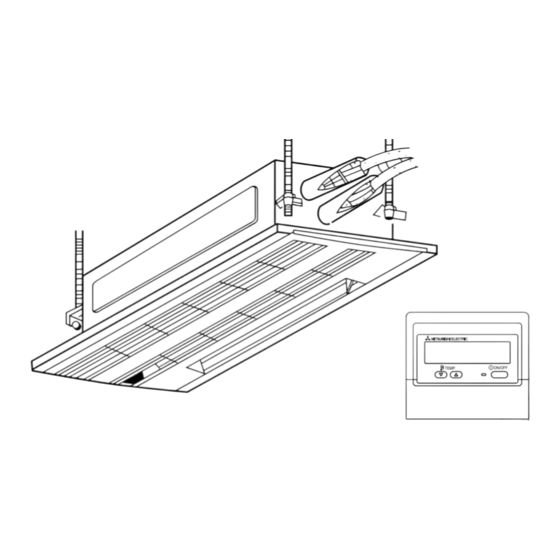
- Page 60 7. Electrical work 7. Elektroarbeiten 7. Installations électriques 7. Elektrische aansluitingen 7. Collegamenti elettrici 7.3. Remote controller For wired remote controller 1) Installing procedures (1) Select an installing position for the remote controller. The temperature sensors are located on both remote controller and indoor unit. s Procure the following parts locally: Two piece switch box Thin copper conduit tube...
- Page 61 7. Trabajo eléctrico 7. Trabalho de electricidade 7. ∏ÏÂÎÙÚÈΤ˜ ÂÚÁ·Û›Â˜ 7. Elektrik iflleri 中 7. Электрические работы 7.3. Control remoto 7.3. Controlo remoto Para el controlador remoto cableado Para controlo remoto com fio 1) Procedimientos de instalación 1) Instruções de instalação (1) Seleccione una posición adecuada para el control remoto.
- Page 62 7. Electrical work 7. Elektroarbeiten 7. Installations électriques 7. Elektrische aansluitingen 7. Collegamenti elettrici (2) Seal the service entrance for the remote controller cord with putty to prevent possible invasion of dew drops, water, cockroaches or worms. A For installation in the switch box: B For direct installation on the wall select one of the following: •...
- Page 63 7. Trabajo eléctrico 7. Trabalho de electricidade 7. ∏ÏÂÎÙÚÈΤ˜ ÂÚÁ·Û›Â˜ 7. Elektrik iflleri 中 7. Электрические работы (2) Selle la entrada del cable del control remoto con masilla para evitar que puedan (2) Vede a entrada de serviço do fio do controlo remoto com betume para evitar a entrar gotas de rocío, agua, cucarachas o gusanos.
- Page 64 7. Electrical work 7. Elektroarbeiten 7. Installations électriques 7. Elektrische aansluitingen 7. Collegamenti elettrici 2) Connecting procedures 1 Connect the remote controller cord to the terminal block. A To TB5 on the indoor unit B TB6 (No polarity) 2 Set the dip switch No.1 shown below when using two remote controller’s for the same group.
- Page 65 7. Trabajo eléctrico 7. Trabalho de electricidade 7. ∏ÏÂÎÙÚÈΤ˜ ÂÚÁ·Û›Â˜ 7. Elektrik iflleri 中 7. Электрические работы 2) Procedimientos de conexión 2) Instruções de instalação 1 Conecte el cable del control remoto en el bloque de terminales. 1 Ligue o fio do controlo remoto ao bloco terminal. A Al terminal TB5 de la unidad interior A Ao TB5 na unidade interior B TB6 (Sin polaridad)
- Page 66 7. Electrical work 7. Elektroarbeiten 7. Installations électriques 7. Elektrische aansluitingen 7. Collegamenti elettrici <SW No. 2> SW contents Main When remote controller power turned on ON/OFF Normally on/Timer mode on When you want to return to the timer mode when the power is restored Comment after a power failure when a Program timer is connected, select “Timer mode”.
- Page 67 7. Trabajo eléctrico 7. Trabalho de electricidade 7. ∏ÏÂÎÙÚÈΤ˜ ÂÚÁ·Û›Â˜ 7. Elektrik iflleri 中 7. Электрические работы <SW No 2> <SW “nº 2”> contenidos del SW Funções principais dos Cuando el suministro de energía del control remoto está encendido Quando o controlo remoto estiver ligado Principal comutadores SW ENCENDIDO/APAGADO...
- Page 68 7. Electrical work 7. Elektroarbeiten 7. Installations électriques 7. Elektrische aansluitingen 7. Collegamenti elettrici 7.4. Function settings ⁄ Mode number ⁄ Refrigerant address ⁄ Setting number ⁄ Unit number Changing the power voltage setting • Be sure to change the power voltage setting depending on the voltage used. 1 Go to the function setting mode.
- Page 69 7. Trabajo eléctrico 7. Trabalho de electricidade 7. ∏ÏÂÎÙÚÈΤ˜ ÂÚÁ·Û›Â˜ 7. Elektrik iflleri 中 7. Электрические работы 7.4. Ajuste de funciones 7.4. Ajustes de função ⁄ Número de modo ⁄ Dirección de refrigerante ⁄ Número do modo ⁄ Endereço do refrigerante ⁄...
- Page 70 7. Electrical work 7. Elektroarbeiten 7. Installations électriques 7. Elektrische aansluitingen 7. Collegamenti elettrici 6 Press the F buttons to set the mode number (1) to 04. 7 Press the G button and the current set setting number (2) will flash. Use the F button to switch the setting number in response to the power supply voltage to be used.
- Page 71 7. Trabajo eléctrico 7. Trabalho de electricidade 7. ∏ÏÂÎÙÚÈΤ˜ ÂÚÁ·Û›Â˜ 7. Elektrik iflleri 中 7. Электрические работы 6 Presione los botones F para ajustar el número de modo (1) a 04. 6 Pressione as teclas F para ajustar o número de memória (1) a 04. 7 Pulse el botón G;...
- Page 72 7. Electrical work 1 1 1 1 1 PLH/PLA- PLH/PLA- PCH/PCA- PKH/PKA- PKH/PKA- PSH/PSA- 2 Mode no. 3 Setting no. PMH-P·BA P·AA(H) P·KA(H) P·GA(H) P·GAL(H) P·FAL(H) P·GA(H) – – – – – – – – – – – – – –...
- Page 73 7. Elektroarbeiten 7. Installations électriques Andere Funktionswahlen Tabelle 1: Standardeinstellung Anlage Nr. 00 wählen 2Betriebsart Nr. 3Einstellung Nr. Einstellung Betriebsart Einstellungen Automatische Wiederherstellung nach Netzstromausfall Nicht verfügbar Verfügbar Erkennung der Innentemperatur Betriebsdurchschnitt der Innenanlage Einstellung durch Fernbedienung der Innenanlage Interner Sensor der Fernbedienung LOSSNAY-Verbindung Nicht unterstützt Unterstützt (Innenanlage nicht mit Außen-Lufteinlaß...
- Page 74 7. Elektrische aansluitingen 7. Collegamenti elettrici Overige functieselecties Tabel 1: Begininstellingen Selecteer eenheidnummer 00 2Modusnummer 3Instellingsnummer Modus Instellingen Instelling Automatisch herstel van stroomuitval Niet beschikbaar Beschikbaar Binnentemperatuurdetectie Binnenapparaat gemiddelde werking Instellen met afstandsbediening van binnenapparaat Interne sensor van afstandsbediening LOSSNAY-verbinding Niet ondersteund Ondersteund (binnenapparaat is niet voorzien van buitenluchttoevoer) Ondersteund (binnenapparaat is voorzien van buitenluchttoevoer)
- Page 75 7. Trabajo eléctrico 7. Trabalho de electricidade Selección de otras funciones Tabla 1: ajuste inicial Seleccione el número de unidad 00 2Núm. de modo 3Núm. de ajuste Modo Ajustes Ajuste Recuperación automática de fallo de alimentación No disponible Disponible Detección de la temperatura de la sala Media de funcionamiento de la unidad interior Ajustada por el control remoto de la unidad interior Sensor interno del control remoto...
- Page 76 7. ∏ÏÂÎÙÚÈΤ˜ ÂÚÁ·Û›Â˜ 7. Elektrik iflleri ÕÏϘ ÂÈϤÍÈ̘ ÏÂÈÙÔ˘ÚÁ›Â˜ ¶›Ó·Î·˜ 1: ∞Ú¯È΋ Ú‡ıÌÈÛË ∂ÈϤÍÙ ÙÔ ÓÔ‡ÌÂÚÔ Ù˘ ÌÔÓ¿‰·˜ 00 2∞Ú. ÏÂÈÙÔ˘ÚÁ›·˜ 3∞Ú. ƒ˘ıÌÈÛ˘ §ÂÈÙÔ˘ÚÁ›· ƒ˘ıÌ›ÛÂȘ ƒ‡ıÌÈÛË ∞˘ÙfiÌ·ÙË Â·Ó·ÊÔÚ¿ ÌÂÙ¿ ·fi ‰È·ÎÔ‹ Ú‡̷ÙÔ˜ ªË ‰È·ı¤ÛÈÌË ¢È·ı¤ÛÈÌË ∞Ó›¯Ó¢ÛË ÂÛˆÙÂÚÈ΋ ıÂÚÌÔÎÚ·Û›·˜ ª¤ÛË ÏÂÈÙÔ˘ÚÁ›· ÂÛˆÙÂÚÈ΋˜ ÌÔÓ¿‰·˜ ƒ˘ıÌ›˙ÂÙ·È...
- Page 77 中 7. Электрические работы Другие выборы функций Таблица 1: Первоначальная настройка Выберите номер прибора 00 Режим Установки 2Номер режима 3Номер установки установка Автоматическое восстановление после сбоя питания Отсутствует Имеется Определение температуры в помещении Средняя величина при работе внутреннего прибора Устанавливается с пульта дистанционного управления внутреннего прибора Внутренний...
- Page 78 7. Electrical work 7. Elektroarbeiten 7.5. Field electrical wiring (Power wiring specifications) Models (Outdoor unit) P1.6, 2, 2.5V P3, 4V P1.6, 2, 2.5, 3, 4Y P5, 6Y Indoor unit power supply ~/N (single), 50Hz, 220 - 230 - 240V Outdoor unit Phase ~/N (Single) 3N ~ (3ph)
- Page 79 7. Installations électriques 7. Elektrische aansluitingen 7.5. Câblage des champs électriques (Spécifications du câblage des circuits d’alimentation) Modèles (Appareil extérieur) P1.6, 2, 2.5V P3, 4V P1.6, 2, 2.5, 3, 4Y P5, 6Y Alimentation de l’appareil intérieur ~/N (Monophasé), 50Hz, 220 - 230 - 240V Appareil extérieur Phase ~/N (Monophasé)
- Page 80 7. Collegamenti elettrici 7. Trabajo eléctrico 7.5. Collegamenti elettrici locali (Specifiche dei cablaggi dell’alimentazione) Modelli (Sezione esterna) P1.6, 2, 2.5V P3, 4V P1.6, 2, 2.5, 3, 4Y P5, 6Y Alimentazione sezione interna ~/N (Monofase), 50Hz, 220 - 230 - 240V Sezione esterna Fase ~/N (Monofase)
- Page 81 7. Trabalho de electricidade 7. ∏ÏÂÎÙÚÈΤ˜ ÂÚÁ·Û›Â˜ 7.5. Cablagem eléctrica (Especificações da cablagem eléctrica) Modelos (Unidade exterior) P1.6, 2, 2.5V P3, 4V P1.6, 2, 2.5, 3, 4Y P5, 6Y Corrente da unidade interior ~/N (Monofásica), 50Hz, 220 - 230 - 240V Unidade exterior Fase ~/N (Monofásica)
- Page 82 7. Elektrik iflleri 中 7.5. Alan elektrik kablo ba¤lant›lar› (Elektrik kablo ba¤lant› spesifikasyonlar›) Modeller (D›fl ünite) P1.6, 2, 2.5V P3, 4V P1.6, 2, 2.5, 3, 4Y P5, 6Y ‹ç ünite güç kayna¤› ~/N (Tek), 50Hz, 220 - 240V D›fl ünite ~/N (Tek) 3N ~ (3 Faz) Güç...
- Page 83 7. Электрические работы 7.5. Электропроводка на месте монтажа (Описание проводки электропитания) Модели (Наружный прибор) P1.6, 2, 2.5V P3, 4V P1.6, 2, 2.5, 3, 4Y P5, 6Y Электропитание внутреннего прибора ~/N (однофазный), 50Гц, 220-230-240В Наружный прибор Фаза ~/N (однофазный) 3N ~ (трёхфазный) Электропитание...
-
Page 84: Marche D'essai
8. Test run 8. Testlauf 8. Marche d’essai 8. Proefdraaien 8. Prova di funzionamento 8.1. Before test run s After completing installation and the wiring and piping of the indoor and outdoor units, check for refrigerant leakage, looseness in the power supply or control wiring, and wrong polarity. -
Page 85: Prueba De Funcionamiento
8. Prueba de funcionamiento 8. Ensaio 8. ¢ÔÎÈÌ·ÛÙÈ΋ ÏÂÈÙÔ˘ÚÁ›· 8. Çal›flma testi 中 8. Выполнение испытания 8.1. Antes de realizar las pruebas 8.1. Antes do ensaio s Después de la instalación de tubos y cables en las unidades interior y exterior, s Após a instalação, a cablagem e a tubagem das unidades interior e exterior compruebe que no haya escapes de refrigerante, aflojamiento en la fuente de ali- ficam completas. - Page 86 8. Test run 8. Testlauf 8. Marche d’essai 8. Proefdraaien 8. Prova di funzionamento Measure an impedance between the power supply terminal block on the outdoor unit and the ground with a 500 V Megger and check that it is equal to or greater than 1.0 MΩ.
- Page 87 8. Prueba de funcionamiento 8. Ensaio 8. ¢ÔÎÈÌ·ÛÙÈ΋ ÏÂÈÙÔ˘ÚÁ›· 8. Çal›flma testi 中 8. Выполнение испытания Mida la impedancia entre el bloque de terminales de la fuente de alimentación de la Meça a impedância entre o bloco terminal da fonte de alimentação na unidade unidad exterior y el suelo con un megaóhmetro de 500V y compruebe que sea exterior e no solo com um meghómetro de 500 V e verifique se é...
- Page 88 8. Test run 8. Testlauf 8. Marche d’essai 8. Proefdraaien 8. Prova di funzionamento Outdoor Unit 1) PUH Type SW4-1 Cooling operation SW4-2 SW4-1 Heating operation SW4-2 2) PU Type SW4-1 Cooling operation SW4-2 ON or OFF * After performing the test run, set SW4-1 to OFF. Outdoor controller board <SW4>...
- Page 89 8. Prueba de funcionamiento 8. Ensaio 8. ¢ÔÎÈÌ·ÛÙÈ΋ ÏÂÈÙÔ˘ÚÁ›· 8. Çal›flma testi 中 8. Выполнение испытания Unidad exterior Unidade exterior 1) Tipo PUH 1) Tipo PUH SW4-1 SW4-1 ON (ligado) Funcionamiento del enfriamiento Operação de refrigeração SW4-2 SW4-2 OFF (desligado) SW4-1 SW4-1 Funcionamiento del de la calefacción...
- Page 90 8. Test run 8. Testlauf Refrigerant address Example CENTRALLY CONTROLLED 1Hr. ON OFF ˚C CHECK CLOCK FILTER ˚C CHECK MODE STAND BY INDOOR UNIT ERROR CODE FUNCTION NOT AVAILABLE DEFROST ADDRESS NO OA UNIT ADDRESS NO CHECK IC : Indoor unit Check code TEMP.
- Page 91 8. Marche d’essai 8. Proefdraaien 8. Prova di funzionamento • Pour une description détaillée de chacun des codes de vérification, consulter le tableau suivant. 1 Code de vérification 2 Tonalité 3 Voyant OPE Symptôme Un seul bip × 1 Allumé pendant une seconde × 1 Erreur de détecteur d’aspiration Un seul bip ×...
- Page 92 8. Prueba de funcionamiento 8. Ensaio 8. ¢ÔÎÈÌ·ÛÙÈ΋ ÏÂÈÙÔ˘ÚÁ›· • Para acceder a la descripción de cada uno de los códigos, consulte la tabla siguiente. 1 Código de 2 Sonido del zumbador 3 LED OPE Síntoma comprobación Encendido durante 1 seg. × 1 Error del sensor de entrada 1 sonido simple Encendido durante 1 seg.
- Page 93 8. Çal›flma testi 中 8. Выполнение испытания • Her kontrol kodunun tan›m› için afla¤›daki tabloya bak›n. 1 Kontrol kodu 2 Alarm sesi 3 OPE LED Belirti Girifl sensör hatas› 1 kere tek bip 1 kere 1 saniye yanar Boru sensör hatas› 2 kere tek bip 2 kere 1 saniye yanar Drenaj sensörü...
- Page 94 8. Test run 8. Testlauf • If the unit cannot be operated properly after the above test run has been performed, refer to the following table to remove the cause. Symptom Cause Wired remote controller LED 1, 2 (PCB in outdoor unit) •...
- Page 95 8. Marche d’essai 8. Proefdraaien • Si vous ne parvenez pas à faire fonctionner l’appareil correctement après avoir mené à bien le test d’essai indiqué ci-dessus, consulter le tableau suivant pour en trouver la cause éventuelle. Symptôme Cause Télécommande filaire Témoin 1, 2 (circuit de l’appareil extérieur) Pendant environ 2 LED 1 et 2 sont allumés, LED 2 s’éteint, puis...
- Page 96 8. Prova di funzionamento 8. Prueba de funcionamiento • Qualora non sia possibile far funzionare l’unità correttamente dopo aver eseguito la prova di funzionamento di cui sopra, fare riferimento alla tabella sottostante per eliminare la causa della disfunzione. Sintomo Motivo Comando a distanza con filo LED 1, 2 (scheda a circuiti stampati della sezione interna) LED 1 e LED 2 sono accesi, quindi LED 2 si...
- Page 97 8. Ensaio 8. ¢ÔÎÈÌ·ÛÙÈ΋ ÏÂÈÙÔ˘ÚÁ›· • Se não for possível utilizar correctamente a unidade após o teste anterior ter sido levado a cabo, consulte o quadro que se segue para eliminar a causa do problema. Sintoma Causa Controlo remoto com fio LED 1, 2 (placa de circuito impresso na unidade exterior) Durante cerca de 2 Depois do LED 1, 2 acende, LED 2 é...
- Page 98 8. Çal›flma testi 中 • Yukar›daki test çal›flt›rmas› yap›ld›ktan sonra ünite gerekti¤i gibi çal›flt›r›lamazsa, nedenini ortadan kald›rmak için afla¤›daki tablo bak›n›z. Belirti Nedeni Kablolu Uzaktan Kumanda LED 1, 2 (d›fl ünitedeki PCB) Elektrik flalterinin • Sistemin çal›flmaya bafllama süreci nedeniyle, elektrik LED 1 ve 2 yan›yor, LED 2 sönüyor, sonra aç›lmas›ndan sonra flalterinin aç›lmas›ndan sonra 2 dakika kadar uzaktan...
- Page 99 8. Выполнение испытания • Если прибор не работает должным образом после проведения пробного прогона, устраните неисправность, обратившись к нижеприведенной таблице. Симптом Причина Проводной пульт дистанционного управления СИД 1, 2 (печатная плата на наружном приборе) В течение • В течение приблизительно 2 минут после включения питания После...
-
Page 100: Contrôle Du Système
9. System control 9. Kontrolle des Systems 9. Contrôle du système 9. Het systeem controleren 9. Controllo del sistema E Refrigerant address = 00 9.1. Wiring the transmission wire SW 1 - 3 ~ 6 A Outdoor unit E Standard 1:1 (Refrigerant address = 00) B Indoor unit F Simultaneous twin (Refrigerant address = 01) C Master remote controller... -
Page 101: Sistema De Control
9. Sistema de control 9. Controlo do sistema 9. ŒÏÂÁ¯Ô˜ Û˘ÛÙ‹Ì·ÙÔ˜ 9. Sistem kontrolü 中 9. Управление системой 9.1. Cableado de transmisión 9.1. Cablagem do fio de transmissão A Unidad exterior E Estándar 1:1 (Dirección de refrigerante = 00) A Unidade exterior E Padrão 1:1 (Endereço de refrigerante = 00) B Unidad interior F Doble simultáneo (Dirección de refrigerante = 01) -
Page 102: Installer La Grille
10. Installing the grille 10. Anbringung des Gitters 10. Installer la grille 10. Het rooster installeren 10. Installazione della griglia 10.1. Checking the contents • This kit contains the following parts. Accessory name Q’ty Remark Grille M5 × 0.8 × 16 Screw 4 ×... -
Page 103: Instalación De La Rejilla
10. Instalación de la rejilla 10. Instalação da grelha 10. ¶Ò˜ ÙÔÔıÂÙÔ‡ÓÙ·È ÔÈ ÁÚ›ÏȘ 10. Izgaran›n tak›lmas› 中 10. Установка вентиляционной решетки 10.1. Comprobación de los contenidos 10.1. Verificação do conteúdo • Este kit contiene las siguientes piezas. • Este kit contém as seguintes peças. Nombre accesorio Cant. - Page 104 10. Installing the grille 10. Anbringung des Gitters 10. Installer la grille 10. Het rooster installeren 10. Installazione della griglia Fig. 3 10.3. Installing the grille • Open the intake grille by pressing on the place marked Push, and remove the air filter.
- Page 105 10. Instalación de la rejilla 10. Instalação da grelha 10. ¶Ò˜ ÙÔÔıÂÙÔ‡ÓÙ·È ÔÈ ÁÚ›ÏȘ 10. Izgaran›n tak›lmas› 中 10. Установка вентиляционной решетки 10.3. Instalación de la rejilla 10.3. Instalação da grelha • Abra la rejilla interior presionando en el lugar marcado mediante PUSH y extraiga •...
- Page 106 10. Installing the grille 10. Anbringung des Gitters 10. Installer la grille 10. Het rooster installeren 10. Installazione della griglia Fig. 4 • Adjust the front panel so that it fits properly in the angle between the ceiling and the wall, and install the securing bolts 2 (supplied with this grille) in their four places at left and right, leaving them slightly loose.
- Page 107 10. Instalación de la rejilla 10. Instalação da grelha 10. ¶Ò˜ ÙÔÔıÂÙÔ‡ÓÙ·È ÔÈ ÁÚ›ÏȘ 10. Izgaran›n tak›lmas› 中 10. Установка вентиляционной решетки • Ajuste el panel frontal de modo que encaje adecuadamente en el ángulo entre el • Ajuste o painel dianteiro de modo a que este encaixe devidamente entre o tecto e techo y la pared e instale los pernos de fijación 2 (suministrados con esta rejilla) o muro, monte os parafusos de segurança 2 (fornecido com esta grelha) nas en sus cuatro ubicaciones respectivas a izquierda y derecha, dejándolos ligera-...
- Page 108 10. Installing the grille 10. Anbringung des Gitters 10. Installer la grille 10. Het rooster installeren 10. Installazione della griglia Fig. 5 10.4. Checks after installing • Check that there are no gaps between the indoor unit and the front panel, and between the front panel and the ceiling surface.
- Page 109 10. Instalación de la rejilla 10. Instalação da grelha 10. ¶Ò˜ ÙÔÔıÂÙÔ‡ÓÙ·È ÔÈ ÁÚ›ÏȘ 10. Izgaran›n tak›lmas› 中 10. Установка вентиляционной решетки 10.4. Comprobaciones a realizar después de la insta- 10.4. Verificações depois da instalação lación • Verifique se não existem folgas entre a unidade interna e o painel dianteiro, e entre o painel dianteiro e a superfície do tecto.
- Page 110 This product is designed and intended for use in the residential, commercial and light-industrial environment. • Low Voltage Directive 73/23/EEC The product at hand is • Electromagnetic Compatibility Directive 89/ based on the following EU regulations: 336/EEC • Machinery Directive 98/37/EC Please be sure to put the contact address/telephone number on this manual before handing it to the customer.
Need help?
Do you have a question about the Mr. SLIM PMH-P 1BA Series and is the answer not in the manual?
Questions and answers