Table of Contents
Advertisement
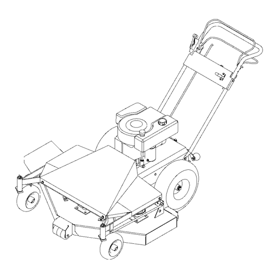
OWNER'S
MANUAL
MODEL NO.
WB80042F
Read and follow all Safety
Rules and Instructions
before operating this
equipment.
Rev. 12.18.00
1602 CORPORATE DRIVE, P.O. BOX 67, WARRENSBURG, MISSOURI 64093
Manufacturing quality lawn care equipment since 1945
ONWB842
Visit us at: www.swisherinc.com
Assembly
Operation
Service and Adjustment
Repair Parts
PHONE (660) 747-8183 FAX (660) 747-8650
Made In The
US A
Advertisement
Table of Contents

Summary of Contents for Swisher WB80042F
-
Page 1: Service And Adjustment
OWNER’S MANUAL MODEL NO. WB80042F Read and follow all Safety Rules and Instructions before operating this equipment. Rev. 12.18.00 1602 CORPORATE DRIVE, P.O. BOX 67, WARRENSBURG, MISSOURI 64093 PHONE (660) 747-8183 FAX (660) 747-8650 Manufacturing quality lawn care equipment since 1945 ONWB842 Visit us at: www.swisherinc.com... -
Page 2: Limited Warranty
1-800-222-8183. The model number, serial number, date of purchase, and the name of the authorized Swisher dealer from whom you purchased the mower will be needed before any warranty claim can be processed. -
Page 3: Safety Instructions
SAFETY INSTRUCTIONS This Safety Alert Symbol indicates important messages in this manual. When you see this symbol, carefully read the message that follows and be alert to the possibility of personal injury. Read this manual completely. This machine is capable of amputating hands and feet, and throwing objects. - Page 4 Refer to provided instructions for proper operation and installation of accessories. Use only accessories and parts approved by Swisher Mower and Machine Co. Inc. Never tamper with safety devices. Check their proper operation regularly. Stop and inspect the equipment if you strike an object.
-
Page 5: Safety And Operational Decals
SAFETY AND OPERATIONAL DECALS Replace decal immediately if damaged. Order by part number from Swisher Mower and Machine Co. Inc. OD36 – DEFLECTOR DECAL OD30 – WARNING DECAL OD55 – DANGER DECAL OD43 – FLYING DEBRIS DECAL OD29 – SPINNING BLADE DECAL... -
Page 6: Slope Operation
OPERATING YOUR NEW CUTTER The operation of any cutter can encounter foreign objects to be thrown into the eyes, resulting in severe eye damage. Always wear certified safety glasses or wide-vision safety goggles for over spectacles before staring any cutting machine and while operating such a machine. - Page 7 BLADE ENGAGE An “OPERATOR PRESENCE” bail and a “BLADE ENGAGE” latch together control engaging the mowers blades. The bail must be engaged before activating the latch. Releasing the “OPERATOR PRESENCE” bail will disengage both the blade and the “BLADE ENGAGE” latch. STARTING THE ENGINE See engine manufacturer’s instructions for the type and...
- Page 8 BACKING UP Disengage blades by releasing “OPERATOR PRESENCE” bail. Engine will stop if blades are not disengaged. Check behind you for safety. Move transaxle into “REVERSE” position. Activate “GROUND CONTROL” bail. Avoid sudden acceleration by slowly squeezing the bail control. TRANSPORTING Disengage blades.
-
Page 9: Cutter Maintenance
GENERAL RECOMMENDATIONS The warranty on this cutter does not cover items that have been subjected to operator abuse or negligence. To receive full value from the warranty, operator must maintain unit as instructed in this manual. Some adjustments will need to be made periodically to maintain your unit properly. All adjustments in the service and adjustments section of this manual should be checked at least once each season. -
Page 10: Service And Adjustments
SERVICE AND ADJUSTMENTS Stop engine, let all moving parts come to a complete stop. Disconnect spark plug. BLADE SPINDLE BELT BLADE SPINDLE BELT REPLACEMENT REMOVAL Stop engine, let all moving parts come to a complete stop. Disconnect spark plug. Remove belt cover. Remove Blade Drive Belt. - Page 11 WHEEL DRIVE BELT REPLACEMENT REMOVAL Stop engine, let all moving parts come to a complete stop. Disconnect spark plug. Remove belt cover. Remove Blade Drive Belt, (See “Blade Drive Belt replacement”) Locate belt guide for wheel drive belt and loosen. Remove wheel drive belt.
-
Page 13: Replacement Parts
When ordering painted parts, please indicate with corresponding letters: C = Red Parts; TK = Textured Black Parts (ex. 4207TK, 4237C) Item # Description Motor Base Wire Link Link Spring 5/16-18 Serrated Flange Nut 5/16-18 x 21/2 Grade 5 Bolt Shift Linkage Blade Driver Housing Brake Spring... - Page 14 When ordering painted parts, please indicate with corresponding letters: C = Red Parts; TK = Textured Black Parts (ex. 4207TK, 4237C) Item # Description Tension Spring 1/2 x 1 9/16 Shoulder Bolt 5/16 SAE Washer 3/8-16 Grade 2 Nut 5/16-18 Nylock Nut Tension Idler Kit Blade Engage Pulley Blade Drive Belt...
- Page 15 REPLACEMENT PARTS When ordering painted parts, please indicate with corresponding letters: C = Red Parts; TK = Textured Black Parts (ex. 4207TK, 4237C)
- Page 16 All cutter parts listed herein may be ordered directly from Swisher Mower & Machine Co. Inc. or your nearest Swisher dealer. All engine parts may be ordered from the nearest dealer of the...


Need help?
Do you have a question about the WB80042F and is the answer not in the manual?
Questions and answers