Table of Contents
Troubleshooting

Related Manuals for Mindray DPM 3


Summary of Contents for Mindray DPM 3
- Page 3 Intellectual Property Statement Mindray DS USA, Inc. (hereinafter called Mindray DS) owns the intellectual property rights to this product and this manual. This manual may refer to information protected by copyrights or patents and does not convey any license under the copyright and the patent rights of Mindray DS, nor the rights of others.
- Page 4 FOR YOUR NOTES...
- Page 5 Preface Manual Purpose This manual provides detailed information about the assembling, dissembling, testing and troubleshooting of the equipment to support effective troubleshooting and repair. It is not intended to be a comprehensive, in-depth explanation of the product architecture or technical implementation.
- Page 6 FOR YOUR NOTES...
-
Page 7: Table Of Contents
Contents 1 Safety ..........................1-1 1.1 Safety Information ......................1-1 1.1.1 Warnings......................1-2 1.1.2 Cautions ......................1-2 1.1.3 Notes ........................1-2 1.2 Equipment Symbols ......................1-3 2 Theory of Operation ......................2-1 2.1 Introduction........................2-1 2.2 System Structure ......................2-1 2.3 Hardware Structure ...................... - Page 8 4.5 Troubleshooting Guide....................4-2 4.5.1 Power On/Off Failures ..................4-2 4.5.2 Display Failure ....................4-3 4.5.3 LED Digital Display & Indication Lamp Failure..........4-3 4.5.4 Alarm Problems....................4-3 4.5.5 Button Failure..................... 4-4 4.5.6 Recorder Failures ....................4-4 4.5.7 Interface Failures....................4-5 4.5.8 Power Supply Failures ..................
-
Page 9: Safety
Safety 1.1 Safety Information WARNING Indicates a potential hazard or unsafe practice that, if not avoided, could result in death or serious injury. CAUTION Indicates a potential hazard or unsafe practice that, if not avoided, could result in minor personal injury or product/property damage. NOTE Provides application tips or other useful information to ensure better maintenance operation. -
Page 10: Warnings
1.1.1 Warnings WARNING Disassembly and repair of this product should be conducted by Mindray DS authorized personnel only. To avoid explosion hazard, do not use the equipment in the presence of flammable anesthetics, vapors or liquids. Follow the applicable waste control regulations to dispose of the package material and keep it out of children’s reach. -
Page 11: Equipment Symbols
1.2 Equipment Symbols Attention (Consulting this Up button manual). Power On/Off Confirm button Alternating current (AC) Down button Battery indicator Pulse Rate (PR) Type applied part. Neonate Defibrillator-proof NIBP start/stop button Pediatric Patient Information Adult Main menu Equipotential grounding Set alarms Nurse Call connector Display Tabular Trends/Pleth RS-232 connector... - Page 12 FOR YOUR NOTES...
-
Page 13: Theory Of Operation
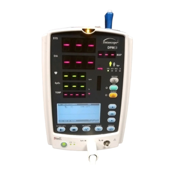
Theory of Operation 2.1 Introduction The monitor is intended for monitoring the patient’s vital signs including non-invasive blood pressure (NIBP), pulse oxygen saturation (SpO ) and pulse rate (PR) for single adult, paediatric and neonatal patient. It is also designed to monitor the temperature Temp) for single adult and paediatric patient. - Page 14 The system’s PCBAs are connected as shown below:...
-
Page 15: Hardware Structure
Power board VS-800 Mindray SpO2 module does not require the isolation power board. The core of the system is the main board which provides power supply for all parameter modules. The parameter modules directly communicate with the main board, and the measurements and status of all modules are processed by the main board and then displayed on the key&display board. -
Page 16: Main Board
2.3.1 Main Board The main board provides resources and supports for the overall system. It controls LCD, LED, keyboard, speaker and recorder. It also enables to communicate with parameter modules and connectors. 2.3.1.1 Principle Diagram Watchdog E 2 PROM Ethernet RTL8201 Nurse Call Serial port 0... -
Page 17: Power Board
2.3.2 Power Board The power board converts the input power (AC mains or battery) to different working voltages for other boards; it also has the function of charging battery. 2.3.2.1 Principle Diagram 16.8V OVP&OCP Rectifier output Rectifer & DC/DC input Flyback &... -
Page 18: Key&Displays Board
2.3.3 Key&displays Board The key&displays board provides the user’s interface. The LCD module, 7-segment digital display, LED indication lamp and keys are integrated on the board. 2.3.3.1 Principle Diagram LCD signal FSTN LCD module LED&KEY CPLD 3.3V Start-up disable circuit detection 3.3V matrix... -
Page 19: Parameter Boards
2.3.4 Parameter Boards 2.3.4.1 SpO2 Module The principle diagram of SpO2 module is shown below: /RST Isolated Serial WATCHDOG In/Output Port HOST 4KV Isolated DRAM +12V Power Supply DRIVE DAC +3.3V FLASH LED DRIVE CIRCUITRY SENSOR CONVERTER GAIN CONTROL OFFSET DAC CIRCUITRY PROGRAMMABLE GAIN OFFSET... - Page 20 2.3.4.2 NIBP Module The principle diagram of NIBP module is shown below: PRESSURE PRESSURE SIGNAL OVER SENSOR AMPLIFIED PRESSURE CUFF CIRCUITS PROTECT PROTECT CIRCUIT PROTECT ASYNCHRONOUS WATCHDO SERIAL COMMUNICATION PRESSURE PRESSURE SIGNAL PRESSURE SIGNAL SENSOR AMPLIFIED CONVERTER CIRCUITS MOTOR CONTROL Windpipe FEEDBACK SIGNAL PUMP AND...
-
Page 21: Recorder
2.3.4.3 Temp Module The principle diagram of Temp module is shown below: Normally, the sensor used for measuring temperature is a thermistor. The resistance of a given thermistor is nonlinearly relative to the temperature. Thus, the resistance of a thermistor can be conversed into temperature. By applying given field current to the thermistor, its resistance can be easily obtained by measuring the voltage on the thermistor. - Page 22 The monitor’s serial port is defined as follows: Definition DPM 3_TX DPM 3_RX VCC(5VDC) Basic settings of the bar code scanner are listed in the table below: Bar code scanner Factory default Host Parameters Baud Rate 9600 9600 Data Bits Stop Bits Calibration bit Handshaking...
- Page 23 Beeper Volume Trigger Mode Scan Data Transmission Format Disable Parameter Scanning 2-11...
- Page 24 FOR YOUR NOTES 2-12...
-
Page 25: Testing And Maintenance
Testing and Maintenance 3.1 Introduction To ensure the monitor always functions normally, qualified service personnel should perform regular inspection, maintenance and test. This chapter provides a checklist of the testing procedures for the monitor with recommended test equipment and frequency. The service personnel should perform the testing and maintenance procedures as required and use appropriate test equipment. -
Page 26: Recommended Frequency
3.1.1 Recommended Frequency Check/Maintenance Item Frequency Visual test When first installed or after reinstalled. Power on test 1. When first installed or after reinstalled. 2. Following any maintenance or the replacement of any main unit parts. NIBP tests Accuracy test 1. -
Page 27: Power-On Test
3.3 Power-On Test This test is to verify that the monitor can power up correctly. The test is passed if the monitor starts up by following this procedure: Insert the lead-acid batteries or lithium battery in the battery compartment and connect the monitor to the AC mains;... - Page 28 Before inflating the metal vessel, the reading of the manometer should be 0. If not, disconnect the airway and reconnect it until the readings is 0. Press the MENU key; select [MAINTAIN >>]→[NIBP CALIBRATE] to start NIBP calibration. Compare the manometer values with the displayed values. The difference should be no greater than ±3mmHg (±0.4kPa).
-
Page 29: Spo 2 Test
3.3.2 SpO Test Tool Required: SpO2 simulator. For the monitor equipped with Mindray DS SpO2 module, BIO-TEK Index-2 SpO2 simulator is recommended. For the monitor equipped with Nellcor SpO2 module, SRC-MAX SpO2 simulator is recommended. For the monitor equipped with Masimo SpO2 module, BIO-TEK Index-2 SpO2 simulator is recommended. -
Page 30: Temp Test
Manufacturer SpO sensor PR (bpm) 96%±3% (without motion) LNCS-NeoPt-L, LNCS Neo-L 96%±3% 80±3 bpm (with motion) (without motion) Masimo 80±5 bpm 96%±2% LNCS Inf-L , LNCS-Pdt, (with motion) (without motion) LNCS-Adtx ,LNCS DC-I,LNCS DC-I 96%±3% (with motion) MAX-A, MAX-P, MAX-I, 96%±2% DS-100A, OXI-A/N (Adult), OXI-P/I, Nellcor... -
Page 31: Nurse Call Performance Test
3.4 Nurse Call Performance Test Tools required: Multimeter Connect the nurse call cable to the analog output connector. Trigger a psychological alarm or a technical alarm. Select [NURSE CALL>>] in the [MAINTAIN] menu. In the [NURSE CALL] menu, select [ALM LEV] and [ALM TYPE]; set [CONTACT TYPE] to [NORMAL OPEN]. -
Page 32: Electrical Safety Tests
3.6 Electrical Safety Tests WARNING Electrical safety tests are a proven means of verifying the electrical safety of the monitor. They are intended for determining potential electrical hazards. Failure to find out these hazards timely may cause personnel injury. Commercialy available test equipment such as safety analyzer can be used for electrical safety tests. -
Page 33: Enclosure Leakage Current Test
Connection of the equipments is shown below: Tools required: Safety analyzer Isolation transformer 3.6.1 Enclosure Leakage Current Test Connect the 601 safety analyzer to an AC power supply (264V, 60 Hz). Connect SUM terminal of the applied part connection apparatus to RA input terminal of 601 safety analyzer, another terminal to the applied part of EUT. -
Page 34: Earth Leakage Current Test
3.6.2 Earth Leakage Current Test Connect the 601 safety analyzer to an AC power supply (264V, 60 Hz). Connect the SUM terminal of the applied part connection apparatus to RA input terminal of 601 safety analyzer, another terminal to the applied part of EUT. Connect the EUT to the 601 analyzer’s auxiliary output connector by using a power cord. -
Page 35: Recorder Check
Bar code recognition configuration Multiligual library General configurations (including passwords, company logo) System functional configuration FPGA program Parameter module programs: SpO2 module (Mindray DS), NIBP module and Temp module. Please refer to help and instructions for program upgrade for details. 3-11... - Page 36 CAUTION Disconnect the monitor from the patient and make sure the important date are saved before upgrade. Do not shut down or power off the equipment when upgrading the bootstrap program. Otherwsie, it may cause the equipemnt to break down. Programs upgrade should be performed by qualified service personnel only.
-
Page 37: Troubleshooting
Troubleshooting 4.1 Introduction In this chapter, monitor problems are listed along with possible causes and recommended corrective actions. Refer to the tables to check the monitor, identify and eliminate the troubles. The troubles we list here are frequently arisen difficulties and the actions were recommended can correct most problems, but not all of them. -
Page 38: Technical Alarm Check
4.4 Technical Alarm Check Check whether technical alarm message is displayed on the monitor before troubleshooting. If an alarm message is presented, eliminate the technical alarm first and troubleshoot in accordance with the following instructions. For further information on technical alarm message, possible cause and corrective action, please refer to the monitor’s Operation Manual. -
Page 39: Display Failure
4.5.2 Display Failure Symptoms Possible Cause Corrective Actions The display is Cables defective or 1. Check whether cables from the display to the black or blank, but poorly connected main board are correctly connected. the monitor still 2. Check whether cables and connectors are works correctly. -
Page 40: Button Failure
Symptoms Possible Cause Corrective Actions No alarm sound is Audio alarm Select [MENU] → [MAINTAIN>>] → [USER issued but alarm disabled MAINTAIN >>] → enter the required password. In lamp lights the pop-up menu, set the [MIN ALARM VOL] to a properly value other than zero. -
Page 41: Interface Failures
Symptoms Possible Cause Corrective Action Poor print quality Paper roll not Stop the recorder and re-install the paper roll or paper not properly installed feeding properly Dirty thermal print 1. Check the thermal print head and the paper roller head for foreign matter. - Page 42 Symptoms Possible Cause Corrective Action Battery unable to be Battery damaged Replace battery and recharge the replacement recharged battery. If the replacement battery can be recharged, the original one fails. Cable defective or 1. Check whether the cable between battery poorly connected interface board and the power module is properly connected...
-
Page 43: Network Related Problems
4.5.9 Network related problems Symptoms Possible Cause Corrective Actions The monitor cannot be No connection to LAN 1. Confirm whether the cables and connected to the CMS. connectors are in good condition and whether the network is correctly connected. 2. Check whether the hub or switch facilities is correctly configured Frequent dropouts and Improper LAN cable... -
Page 44: Bar Code Scanner Failures
4.5.11 Bar Code Scanner Failures Symptoms Possible Cause Corrective Actions Bar code scanner does Bar code scanner not Select [MAINTAIN >>] → [USER not work powered on MAINTAIN >>] → enter required user password; set [BARCODE POWER] to [ON] in the pop-up menu to switch on the bar code scanner. -
Page 45: Spo2 Measurement Failure
4.5.13 SpO2 Measurement Failure Symptoms Possible Cause Corrective Actions Unable to measure SpO2 sensor failure Replace the SpO2 sensor. SpO2 Cables defective Check whether the cable between SpO2 module and the main board is in good condition. SpO2 module failure Replace SpO2 module. - Page 46 FOR YOUR NOTES 4-10...
-
Page 47: Repair And Disassembly
Repair and Disassembly 5.1 Tools During disassembly and replacement, the following tools may be required: Philips screwdrivers Wire cutters Sharp nose pliers M6 spanner 5.2 Preparation for Disassembly Before disassembling the monitor, stop monitoring the patients, turn off the monitor and disconnect all the accessories and peripheral devices. -
Page 48: Disassembly
5.3 Disassembly 5.3.1 Separating the Front and Rear Half of the Monitor If the monitor is configured with Temp module, Unscrew the two M3×6 crosshead screws with a screwdriver as shown in the figure below. Disconnect the wires from the PCBA as shown in the figure below. Unscrew the four M3×20 crosshead screws with a screwdriver(102) as shown in the figure below. - Page 49 If the device is not equipped with a Temp module, Unscrew the four M3×20 crosshead screws directly with a screwdriver(102) as shown in the figure below. NOTE When separating the front and the rear part, use screwdriver(102) instead of screwdriver (107) to unscrew the four M3×20 crosshead screws. Release the clips on the front and rear housings;...
-
Page 50: Disassembling The Front Housing Assembly
NOTE Exercise care when separating the front and the rear housings. Be sure not to damage the cables and connectors. 5.3.2 Disassembling the Front Housing Assembly Unscrew the six M3×6 crosshead screws with a screwdriver and remove the button board. Unscrew the four M3×8 crosshead screws with a screwdriver;... - Page 51 Unscrew the three M3×6 crosshead screws with a screwdriver and take out the SpO rack. Unscrew the M3×6 screw with a screwdriver and take out the SpO module. Mindray DS SpO Masimo SpO module Nellcor SpO module module Unscrew the plastic nut and take out the SpO...
-
Page 52: Removing The Main Rack Assembly
5.3.3 Removing the Main Rack Assembly Unscrew the two M3×6 crosshead screws with a screwdriver and take out the recorder by unclenching the clips. Remove the cables from the recorder and unscrew the M3×6 crosshead screw with a screw driver. Unscrew the five M3×6 crosshead screws with a screwdriver and take out the main rack assembly. -
Page 53: Disassembling Nibp Module
Provided that the device is configured with a Temp module, unscrew the three PT3×8 tapping screws with a screwdriver and then remove the Temp module. 5.3.4 Disassembling NIBP Module Cut the cable tie with a wire cutter Unscrew the three M3×6 crosshead screws with a screwdriver and take out the NIBP rack. -
Page 54: Removing The Main Board
Unscrew the four M3×6 crosshead screws with a screwdriver and take out the NIBP module. 5.3.5 Removing the Main Board Disconnect all the cables connecting the main board and then take out the main board by unscrewing the four M3×6 crosshead screws with a screwdriver. 5.3.6 Removing the Power Board Pull out the cables that connect the power board and remove the power board by unscrewing the three M3×6 crosshead screws with a screwdriver. -
Page 55: Removing The Battery Assembly
5.3.7 Removing the Battery Assembly If the monitor is equipped with the lead-acid battery assembly, unscrew the four M3×8 crosshead screws with a screwdriver. If the monitor is equipped with the lithium battery assembly, unscrew the three M3×6 crosshead screws with a screwdriver. 5.3.8 Removing the Fan and Speaker Cut the cable ties on the fan, speaker and the main rack;... -
Page 56: Removing The Power Socket
5.3.9 Removing the Power Socket Remove the nut securing the grounding post with a spanner and take out the grounding terminal of the power socket. Unscrew the two M3×8 crosshead screws with a screwdriver and remove the power socket. 5.3.10 Removing the Temp Module Remove the Temp probe assembly first. - Page 57 Unscrew the two M3×6 cross head screws with a screwdriver and take out the cover plate. Unscrew the four M3×6 crosshead screws with a screwdriver and remove the Temp module main board. 5-11...
-
Page 58: Removing The Spo 2 Module
5.3.11 Removing the SpO Module Mindray DS SpO module needs not be removed. For Masimo SpO module, remove the isolation power board by unscrewing the three M3 nuts with sharp nose pliers; unscrew the three M3×6 crosshead screws with a screwdriver;... -
Page 59: Parts
Parts 6.1 Main Unit Exploded View Parts List Description 6006-30-39446 Front housing assembly Main rack assembly (for lead-acid batteries) 6006-30-39405 6006-30-39586 Rear housing assembly (with Temp module) M04-000505--- Screw M3×20 M04-004012--- Crosshead screw M3×6... -
Page 60: Main Rack Assembly (For Lead-Acid Batteries)
6.2 Main Rack Assembly (For Lead-acid Batteries) Exploded View... - Page 61 Parts List Description 6006-20-39367 Main rack (for lead-acid batteries) 6006-30-39448 Lead-acid battery assembly M04-004015--- Crosshead screw M3×8 6006-20-39385 Speaker and cables 6006-20-39379 Speaker spacer 6006-20-39464 Power board insulating plate M04-004012--- Crosshead screw M3×6 6006-30-39478 Power board for lead-acid battery M04-000106--- Bolt M3×7+8-6 M04-011002--- M3 nut with spring washer...
-
Page 62: Main Rack Assembly (For Lithium Battery)
6.3 Main Rack Assembly (For Lithium Battery) Exploded View... - Page 63 Parts List Description 6006-20-39416 Main rack (for lithium battery) 6006-30-39449 Lithium battery assembly M04-004012 Crosshead screw M3×6 6006-20-39385 Speaker and cables 6006-20-39379 Speaker spacer 6006-20-39464 Power board insulating sheet M04-011002--- M3 nut with spring washer 6006-30-39393 Power board for lithium battery M04-000106--- Bolt M3×7+8-6 0000-10-10996...
-
Page 64: Front Housing Assembly
6.4 Front housing Assembly Exploded View Parts List Description 6006-20-39358 Front housing 6006-20-39520 Waterproof seal 6006-20-39372 Key pad 6006-20-39431 Key pad fixer M04-021000--- Flat washer 6006-20-39488 Dust proof strip 2 6006-20-39482 LED shade 6006-30-39584 Key pad 6006-30-39471 SpO2 module kit (Masimo) M04-004012--- Crosshead screw M04-011002---... -
Page 65: Rear Housing Assembly
Description 6006-20-39376 Battery door link 6006-20-39359 Battery door M04-003905--- Tapping screw PT3×6 M04-021024--- Flat washer 0010-20-12194 NIBP connector for main unit 047-000214-00 Front housing overlay (with Temp module) 6006-20-39361 Alarm LED cover 6.5 Rear Housing Assembly Exploded View Parts List Description 6006-20-39351 Rear housing... -
Page 66: Lithium Battery Charger Assembly
Description M04-003105--- Tapping screw PT3×8 M04-021024--- Flat washer 6006-20-39350 Handle cover M04-004012--- Crosshead screw M3×6 TR6C-30-16670 TR60-C recorder 6.6 Lithium Battery Charger Assembly Exploded View Parts List Description 6006-20-39417 Lithium battery mounting rack 6006-30-39427 Lithium battery receptacle board M04-030030--- Bolt M3×12 9201-20-36038 Spring M04-000605---... -
Page 67: Lead-Acid Battery Assembly
6.7 Lead-acid Battery Assembly Exploded View Parts List Description 6006-20-39419 Lead-acid battery mounting rack 8002-20-36151 Spring 8002-20-36152 Battery charging flexible support 8002-20-36154 Battery contact M07-00043S--- Switch M04-004015--- Screw M3×8 9000-20-07286 Spring M04-011002--- M3 nut with spring washer M04-051060--- Tapping screw M2.0×8 M04-021000--- Flat washer... -
Page 68: Masimo Spo 2 Board Assembly
6.8 MASIMO SpO Board Assembly Exploded View Parts List Description DA8K-20-14524 insulating plate for SpO2 isolation power board M90-000002--- Insulation washer M04-000301--- Stainless steel nut, GB6170-M3 0010-30-12095 Masimo M7 isolation power board 0010-10-12275 Masimo M7 board(Masimo kit) M04-000104--- Spring washer M04-000106--- Bolt M3×7 6006-20-39366... -
Page 69: Temp Assembly
6.9 Temp Assembly Exploded View Parts List Description 6006-20-39363-51 Temp module housing 1 M04-003905--- Tapping screw PT3×6 6006-20-39364 Temp module housing 2 M04-002505--- Screw M3×6 6006-20-39569 Temp module waterproof pad M04-002505--- Crosshead screw M3×6 M09A-30-62103 Temp main board assembly 6006-20-39365 Temp probe cover pack support 6006-20-39377 Temp probe well... - Page 72 P/N: 046-000179-00 (2.0)
Need help?
Do you have a question about the DPM 3 and is the answer not in the manual?
Questions and answers