Table of Contents
Advertisement
Quick Links
Advertisement
Table of Contents

Related Manuals for Chauvin Arnoux C.A 10141


Summary of Contents for Chauvin Arnoux C.A 10141
- Page 1 GB - User’s manual C.A 10141 Conductivity meter...
- Page 2 The product is declared recyclable following an analysis of the life cycle in accordance with standard ISO 14040. Chauvin Arnoux has adopted an Eco-Design approach in order to design this appliance. Analysis of the complete life- cycle has enabled us to control and optimize the effects of the product on the environment. In particular this appliance exceeds regulation requirements with respect to recycling and reuse.
-
Page 3: Table Of Contents
1.2. Accessories ..................................5 1.3. Replacement parts ................................. 5 1.4. Inserting the batteries ..............................6 2. PRESENTATION OF THE INSTRUMENT ..........................7 2.1. C.A 10141 ..................................7 2.2. Functions of the instrument ............................8 2.3. Keypad ................................... 8 2.4. Display .................................... 9 2.5. -
Page 4: First Use
ÉTAT DE LIVRAISON After sales and calibration department e-mail: info@manumesure.fr WEB : www.manumesure.com Le conductimètre C.A 10141 est livré dans une mallette de www.chauvin-arnoux.com transport avec : Une cellule de conductivité avec sonde de température intégrée XCP4ST1. ATTESTATION DE CONFORMITE Quatre piles alcaline AA ou LR6. -
Page 5: Accessories
1.2. ACCESSORIES „ One adapter DIN male to BNC female (for the cell) and „ One adapter, DIN male to S7 female (for the cell) and female female jack (for a PT1000 temperature probe). The cable jack (for a PT1000 temperature probe). The cable is 1m long. is 10cm long. -
Page 6: Inserting The Batteries
1.4. INSERTING THE BATTERIES „ Turn the instrument over. „ Press the locking tab and lift off the battery compartment cover. „ Remove the rubber plug. „ Insert the 4 batteries provided, with the polarities as shown. Put the rubber plug back in place. Push it in correctly. Place the two front ends before pushing in the central part. -
Page 7: Presentation Of The Instrument
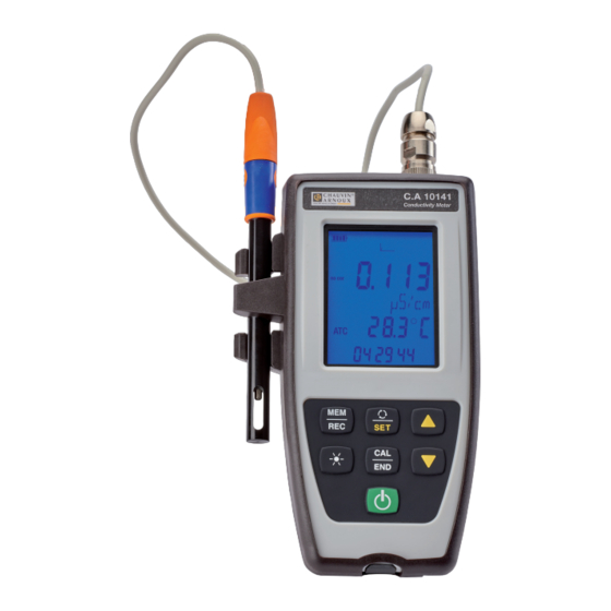
2. PRESENTATION OF THE INSTRUMENT 2.1. C.A 10141 Cable. Tight 8-point connector. Clamping ring. C.A 10141 Conductivity cell. Conductivity Meter Backlit LCD display unit. Keypad with 6 keys. Protecting sheath. On/Off key. Wrist strap. Type B micro USB connector protected by a cap. -
Page 8: Functions Of The Instrument
2.2. FUNCTIONS OF THE INSTRUMENT The C.A 10141 is a conductivity meter in a watertight housing. It is used to measure conductivity, resistivity, TDS (total dissolved solids), salinity, and temperature. This instrument is easy to use. It has extensive stand-alone capabilities and can be used: „... -
Page 9: Display
2.4. DISPLAY MEM FULL SET COR. REF TEMP TDS Display of the measurement. no cor cor lin cor f(T) Display of the unit. CAL SET Display of the temperature. Ref 20°C Ref 25°C Display of the time. Indicates the battery voltage level. When the symbol is empty, the batteries must be replaced. -
Page 10: Setting The Time
2.5. SETTING THE TIME The time of your instrument is set using the Data Logger Transfer software. Refer to §4.4.2 2.6. PROP To make reading easier, the instrument can be set on its prop. -
Page 11: Use In Stand-Alone Mode
3. USE IN STAND-ALONE MODE „ The instrument can operate in two modes: „ the stand-alone mode described in this section, „ the record mode, in which it is controlled by a PC. This mode is described in the next section. To ensure proper operation of the instrument, always leave the cell connected and the cap on the USB connector. - Page 12 „ Long-press the SET key. „ Choose the temperature unit (°C or °F) using the ▲ and ▼ keys. TEMP > 2s „ Press the SET key and use the ▲ and ▼ keys to set the A long press scrolls the values faster. temperature correction.
- Page 13 3.2.2. CHOICE OF STANDARD SOLUTION The C.A 10141 is calibrated for conductivity. The calibration is done at one point. Choose the solution that lies in the range of interest to you. Conductivity at 25°C Conductivity 147 µS/cm 1408 µS/cm 12.85 mS/cm Resistivity 6.8 kΩ.cm...
- Page 14 The instrument displays the conductivity measurement along with the measured temperature, the reference temperature, and the time. ATC = Automatic Temperature Compensation. cor lin Ref 20°C 3.2.3. CALIBRATION PROCEDURE Calibration serves to determine the constant of the conductivity cell. In order to avoid the influence of the temperature, do the calibration at the temperature at which you will be making measurements. „...
- Page 15 „ Confirm the set by pressing the CAL key. „ Choose the calibration set by long presses on the ▲ and ▼ keys. The instrument displays the measured conductivity and the temperature. cor lin CAL SET CAL SET Ref 20°C It performs the conductivity measurement and indicates its progress.
-
Page 16: Conductivity Measurement
3.2.4. RESTORE THE INITIAL CALIBRATION Press the CAL key, then the MEM key. If you do not want to restore the initial calibration, choose no before pressing the CAL key. Otherwise, choose YES and press the CAL key. The cell coefficient returns to 1.000. 3.3. - Page 17 3.3.1. USING ANOTHER CONDUCTIVITY CELL The cell provided with the instrument has an integrated temperature probe. If you use another cell, one without an integrated temperature sensor, you must measure the temperature of the solution. Use a four-pole cell suited to the medium to be measured. The instrument indicates that the temperature can be modified by displaying MTC next to the temperature MTC = Manual Temperature Compensation.
-
Page 18: Resistivity Measurement
3.4. RESISTIVITY MEASUREMENT Resistivity is the reciprocal of conductivity. You must first calibrate the cell for conductivity and parameterize the measurements (in particular the temperature correction and the reference temperature) before making resistivity measurements. „ Long-press the key to switch the instrument on. „... -
Page 19: Tds Measurement
3.5. TDS MEASUREMENT The TDS (Total Dissolved Solids) measurement is used to estimate the level of dissolved solids in a solution. You must first calibrate the cell for conductivity and parameterize the measurements (in particular the temperature correction, the reference temperature, and the TDS factor) before making TDS measurements. „... -
Page 20: Recording The Measurements
3.7. RECORDING THE MEASUREMENTS „ A short press on the MEM key records the measurement with the date and time. The MEM symbol is displayed briefly. It is not possible to record a single/an isolated measurement when/while the instrument is (already?) recording. „... -
Page 21: Use In Recording Mode
4. USE IN RECORDING MODE The instrument can operate in two modes: „ the stand-alone mode described in the previous section, „ the record mode, in which it is controlled by a PC. This mode is described below. 4.1. CONNECTION The instrument communicates by a USB link, using the USB to micro USB cord provided. - Page 22 The instrument is treated as a USB key. Clicking Open the folder and display the files gives you access to its content. This content includes the Set.csv file. You can open this file in a spreadsheet and modify it: „ add or remove a calibration set „...
-
Page 23: Data Logger Transfer Software
4.4. DATA LOGGER TRANSFER SOFTWARE Once the instrument is connected to the PC, open the Data Logger Transfer software. For context-sensitive information about the use of the Data Logger Transfer software, refer to the Help menu. 4.4.1. CONNECTING THE INSTRUMENT „... - Page 24 4.4.4. PROGRAMMED RECORDING SESSIONS By clicking , you can program a recording session. Assign a name to the recording session. Then enter a starting date and time and an ending date and time or a duration. The maximum duration of a recording session depends on the memory available. Choose a sampling period.
- Page 25 4.4.9. FORMATTING THE MEMORY OF THE INSTRUMENT The internal memory of the instrument is already formatted. But if there is a problem (if it becomes impossible to read or to write), it may be necessary to reformat it (in Windows). In this case, all of the data will be lost.
-
Page 26: Technical Characteristics
5. TECHNICAL CHARACTERISTICS 5.1. REFERENCE CONDITIONS Quantity of influence Reference values Temperature 23 ± 3 °C Relative humidity 45% to 75% Battery supply voltage 4 to 6.4 V USB supply voltage 5 V ± 5% Electric field < 1 V/m Magnetic field <... - Page 27 Intrinsic uncertainty of the instrument < 0.4°C < 0.7°F alone without the cell 5.2.6. INFLUENCE OF TEMPERATURE Influence of temperature (from -10°C to 55°C at 50% RH) on the C.A 10141. Type of measurement Typical influence Maximum influence Conductivity measurement > 0.2 µS/cm 0.25%/10°C...
-
Page 28: Memory
5.3. MEMORY The size of the flash memory containing the records is 8 MB. This capacity makes it possible to record 100,000 measurements. Each measurement is recorded with the date and time. 5.4. USB Protocol: USB Mass Storage Maximum transmission speed: 12 Mbit/s Type B micro-USB connector 5.5. -
Page 29: Environmental Conditions
5.6. ENVIRONMENTAL CONDITIONS Instrument for indoor and outdoor use. Altitude < 2000m, and 10,000m in storage. Pollution degree °C -30 -20 1 = Range of reference. 2 = Range of use. 3 = Range for storage ( with neither primary nor rechargeable batteries . Except conductivity cell and standard solutions... -
Page 30: Maintenance
6. MAINTENANCE Except for the batteries, the instrument contains no parts that can be replaced by personnel who have not been specially trained and accredited. Any unauthorized repair or replacement of a part by an “equivalent” may grave- ly impair safety. 6.1. -
Page 31: Replacement Of Batteries
See you on our site: www.chauvin-arnoux.com Then go to “Support”, then “Download our software”, then “C.A 10141”. Updating the embedded software may reset the configuration and cause the loss of the recorded data. As a precaution, save the data in memory to a PC before updating the embedded software. - Page 32 Embedded software update procedure „ Download the .bin file from our web site, then press and hold the MEM key and switch the instrument on by pressing the key. The instrument displays BOOT. > 2s „ Release the keys and the instrument displays COPY, indicating that it is ready to receive the new software. „...
- Page 33 „ Copy the .bin file to the instrument as if were a USB key. „ When the copying is done, press the MEM key and the instrument displays LOAD, indicating that the software is being installed. „ When installation is done, the instrument displays PASS or FAIL according to whether or not the operation succeeded. If installation fails, download the software again and repeat the procedure.
-
Page 34: Warranty
7. WARRANTY Except as otherwise stated, our warranty is valid for 24 months starting from the date on which the equipment was sold. Extract from our General Conditions of Sale provided on request. The warranty does not apply in the following cases: „... -
Page 35: Appendix 1: Nonlinear Temperature Correction Of The Conductivity
8. APPENDIX 1: NONLINEAR TEMPERATURE CORRECTION OF THE CONDUCTIVITY The nonlinear correction concerns natural water: underground water, surface water, drinking water, and sewage. It is defined by ISO/DIN standard 7888, between 0 and 35.9°C. It is especially useful for low conductivity values. The table below indicates the nonlinear correction, f25, applied to refer the conductivity measured at a temperature T to the 25°C reference temperature. -
Page 36: Appendix 2: Salinity Calculation
9. APPENDIX 2: SALINITY CALCULATION Practical salinity Sp, referred to 15°C, is defined by UNESCO using the PSS-78 equation, for a temperature of the solution ranging from -2 to +35°C and a pressure close to one standard atmosphere: − ∑ ∑... - Page 38 FRANCE INTERNATIONAL Chauvin Arnoux Group Chauvin Arnoux Group 190, rue Championnet Tél : +33 1 44 85 44 38 75876 PARIS Cedex 18 Fax : +33 1 46 27 95 69 Tél : +33 1 44 85 44 85 Our international contacts Fax : +33 1 46 27 73 89 info@chauvin-arnoux.com...
Need help?
Do you have a question about the C.A 10141 and is the answer not in the manual?
Questions and answers