Table of Contents
Advertisement
Quick Links
Advertisement
Table of Contents

Related Manuals for Chauvin Arnoux CA 10141E


Summary of Contents for Chauvin Arnoux CA 10141E
- Page 1 EN - User’s manual CA 10141E Conductivity meter...
- Page 2 The product is declared recyclable following an analysis of the life cycle in accordance with standard ISO 14040. Chauvin Arnoux has adopted an Eco-Design approach in order to design this appliance. Analysis of the complete life- cycle has enabled us to control and optimize the effects of the product on the environment. In particular this appliance exceeds regulation requirements with respect to recycling and reuse.
-
Page 3: Table Of Contents
1.2. Accessories ..................................4 1.3. Replacement parts ................................. 4 1.4. Inserting the batteries ..............................5 2. PRESENTATION OF THE INSTRUMENT ..........................6 2.1. CA 10141E ..................................6 2.2. Terminal strip .................................. 6 2.3. Functions of the instrument ............................7 2.4. Keypad ................................... 7 2.5. -
Page 4: First Use
1. FIRST USE 1.1. DELIVERY CONDITION The CA 10141E conductivity meter is delivered in a cardboard with: ■ one protective sheath fitted on the instrument, ■ four AA or LR6 alkaline batteries, ■ one mains-USB adapter, ■ one USB to micro USB cable, ■... -
Page 5: Inserting The Batteries
1.4. INSERTING THE BATTERIES ■ Turn the instrument over. ■ Press the locking tab and lift off the battery compartment cover. ■ Remove the rubber plug. ■ Insert the 4 batteries provided, with the polarities as shown. ■ Put the rubber plug back in place. ■... -
Page 6: Presentation Of The Instrument
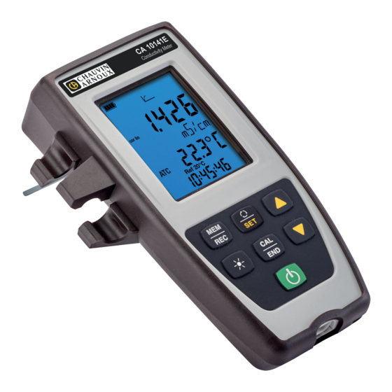
2. PRESENTATION OF THE INSTRUMENT 2.1. CA 10141E Terminal strip. CA 10141E Conductivity Meter Backlit LCD display unit. Keypad with 6 keys. Protecting sheath. On/Off key. Type B micro USB connector protected by a cap. 2.2. TERMINAL STRIP One BNC socket for the measuring probe. -
Page 7: Functions Of The Instrument
2.3. FUNCTIONS OF THE INSTRUMENT The CA 10141E is a conductivity meter designed for use in the laboratory. It is used to measure conductivity, resistivity, TDS (total dissolved solids), salinity, and temperature. It also provides the measurement value and temperature value in the form of a voltage on the analogue output. -
Page 8: Display
2.5. DISPLAY MEM FULL SET COR. REF TEMP TDS Display of the measurement. no cor cor lin cor f(T) Display of the unit. CAL SET Display of the temperature. Ref 20°C Ref 25°C Display of the time. Indicates the battery voltage level. When the symbol is empty, the batteries must be replaced. -
Page 9: Setting The Time
2.6. SETTING THE TIME The time of your instrument is set using the Data Logger Transfer software. Refer to §4.4.2 2.7. PROP To make reading easier, the instrument can be set on its prop. -
Page 10: Use In Stand-Alone Mode
3. USE IN STAND-ALONE MODE ■ The instrument can operate in two modes: ■ the stand-alone mode described in this section, ■ the record mode, in which it is controlled by a PC. This mode is described in the next section. To ensure proper operation of the instrument, always leave the cell connected and the cap on the USB connector. - Page 11 ■ Long-press the SET key. ■ Choose the temperature unit (°C or °F) using the ▲ and ▼ keys. TEMP > 2s ■ Press the SET key and use the ▲ and ▼ keys to set the A long press scrolls the values faster. temperature correction.
- Page 12 3.1.2. CHOICE OF STANDARD SOLUTION The CA 10141E is calibrated for conductivity. The calibration is done at one point. Choose the solution that lies in the range of interest to you. Conductivity at 25°C Conductivity 147 µS/cm 1408 µS/cm 12.85 mS/cm Resistivity 6.8 kΩ.cm...
- Page 13 To measure the temperature, you can: ■ Connect the temperature sensor to the jack socket on the ■ Plunge the thermometer directly in the solution and perform instrument and immerse it in the solution. manual temperature correction (see § 3.2.1). The instrument displays the conductivity measurement and the temperature measured, the reference temperature and the time.
- Page 14 3.1.3. CALIBRATION PROCEDURE Calibration serves to determine the constant of the conductivity cell. In order to avoid the influence of the temperature, do the calibration at the temperature at which you will be making measurements. ■ With the instrument set to conductivity measurement, press the CAL key.
- Page 15 Do not withdraw the cell from the solution until the measurement is over. To abort the calibration of the cell, long-press the END key before the end of the measurement. Otherwise, when the measurement is over, the new calibration is applied. ■...
-
Page 16: Conductivity Measurement
3.2. CONDUCTIVITY MEASUREMENT When the calibration is over, the cell is ready to make measurements. Use a cell suited to the medium to be measured. Between measurements, the cell must be rinsed, then dried. For each measurement, wait for the measurement to stabilize and for the temperature to be correctly established. Conductivity is the capacity of a solution to conduct electric current. -
Page 17: Resistivity Measurement
You must then correct the temperature displayed, using the ▲ and ▼ keys, so that it is equal to the measured temperature of the solution. The instrument corrects the response of the cell as a function of the temperature. To calibrate the cell, always correct the temperature first. 3.3. -
Page 18: Tds Measurement
3.4. TDS MEASUREMENT The TDS (Total Dissolved Solids) measurement is used to estimate the level of dissolved solids in a solution. You must first calibrate the cell for conductivity and parameterize the measurements (in particular the temperature correction, the reference temperature, and the TDS factor) before making TDS measurements. ■... -
Page 19: Recording The Measurements
To see the records, you must use a PC and install the Data Logger Transfer software (see § 4). 3.7. ANALOGUE OUTPUTS The CA 10141E is equipped with 2 analogue outputs (3 x 4 mm banana sockets- red, black and yellow) which supply continuously a voltage proportional to the measurement value and a voltage proportional to the temperature. - Page 20 This configuration is defined in the SetAnalogOutput_Conduc.txt and SetAnalogOutput_T.txt files. To access it, connect the instrument to a PC using the USB / micro-USB cable. The PC “sees” the instrument as a USB drive, so you can read its contents. Use a text editor to open the SetAnalogOutput_Conduc.txt file to see its default contents: SET OUTPUT_0V_CONDUC SET OUTPUT_5V_CONDUC...
-
Page 21: Errors
Er.20: Calibration error. The file defining the set of calibration solutions is missing. Download it from our web site: www.chauvin-arnoux.com Click on the “Support” tab, then search on the name of your instrument “CA 10141E”. Copy the file to the memory of the instrument connected to the PC via USB. -
Page 22: Use In Recording Mode
4. USE IN RECORDING MODE The instrument can operate in two modes: ■ the stand-alone mode described in the previous section, ■ the record mode, in which it is controlled by a PC. This mode is described below. 4.1. CONNECTION The instrument communicates by a USB link, using the USB to micro USB cord provided. - Page 23 This content includes the Set.txt file. You can open this file in a text editor and modify it: ■ add or remove a calibration set ■ modify a calibration set by adding, removing, or modifying standard solutions. Do not change the structure of the file. Number of calibration sets.
-
Page 24: Data Logger Transfer Software
4.4. DATA LOGGER TRANSFER SOFTWARE Once the instrument is connected to the PC, open the Data Logger Transfer software. For context-sensitive information about the use of the Data Logger Transfer software, refer to the Help menu. 4.4.1. CONNECTING THE INSTRUMENT ■... - Page 25 4.4.4. PROGRAMMED RECORDING SESSIONS By clicking , you can program a recording session. Assign a name to the recording session. Then enter a starting date and time and an ending date and time or a duration. The maximum duration of a recording session depends on the memory available. Choose a sampling period.
-
Page 26: Other Software
In this case, all of the data will be lost. 4.5. OTHER SOFTWARE The CA 10141E can be used with the Regressi software via the Heito C320 instrument’s communication protocol and with the Graph2D software via the Heito MPC350 instrument’s communication protocol. -
Page 27: Technical Specifications
5. TECHNICAL SPECIFICATIONS 5.1. REFERENCE CONDITIONS Quantity of influence Reference values Temperature 23 ± 3 °C Relative humidity 45 to 60%RH Battery supply voltage 4 to 6.4 V USB supply voltage 5 V ± 5% Electric field < 1 V/m Magnetic field <... - Page 28 5.2.3. TDS MEASUREMENTS Specified measurement range 0.001 to 4.999 mg/l 5.00 to 49.99 mg/l 50.0 to 499.9 mg/l Resolution (R) 1 µg/l 10 µg/l 100 µg/l Intrinsic uncertainty ± 0.5% L ± R * Specified measurement range 500 to 4999 mg/l 5.00 to 49.99 g/l 50.0 to 200.0 g/l Resolution (R)
-
Page 29: Memory
5.2.8. INFLUENCE OF HUMIDITY Influence of humidity (from 25 to 90% RH at 25°C) on the instrument. Type of measurement Maximum influence ± 1% si < 5.0 µS/cm Conductivity measurement ± 0,25% si < 50.0 mS/cm ± 1% si ≥ 50.0 mS/cm Temperature measurement ±... -
Page 30: Environmental Conditions
The instrument can also be powered via a USB-micro USB cord, connected either to a PC or to a wall outlet via a mains adapter. symbol is displayed in this case. > 110 VAC < 240 VAC 50 / 60 Hz Connecting the external USB supply does not recharge the storage batteries. -
Page 31: Mechanical Characteristics
5.7. MECHANICAL CHARACTERISTICS Dimensions (L x W x D) 211 x 127 x 54mm with the sheath Dimensions (L x W x D) 206 x 97 x 49mm without the sheath Mass of the instrument approximately 600 g including the batteries Mass of batteries approximately 100 g Inrush protection... -
Page 32: Maintenance
6. MAINTENANCE Except for the batteries, the instrument contains no parts that can be replaced by personnel who have not been specially trained and accredited. Any unauthorized repair or replacement of a part by an “equivalent” may gravely impair safety. 6.1. -
Page 33: Calibration Log
See you on our site: www.chauvin-arnoux.com Then go to “Support”, then “Download our software”, then “CA 10141E”. Updating the embedded software may reset the configuration and cause the loss of the recorded data. As a precaution, save the data in memory to a PC before updating the embedded software. - Page 34 ■ Connect the instrument to your PC using the USB cord provided. ■ Copy the .bin file to the instrument as if were a USB key. ■ When the copying is done, press the MEM key and the instrument displays LOAD, indicating that the software is being installed. ■...
-
Page 35: Warranty
7. WARRANTY Except as otherwise stated, our warranty is valid for 24 months starting from the date on which the equipment was sold. The extract from our General Conditions of Sale is available on our website. www.chauvin-arnoux.com/en/general-terms-of-sale The warranty does not apply in the following cases: ■... -
Page 36: Appendix 1: Nonlinear Temperature Correction Of The Conductivity
8. APPENDIX 1: NONLINEAR TEMPERATURE CORRECTION OF THE CONDUCTIVITY The nonlinear correction concerns natural water: underground water, surface water, drinking water, and sewage. It is defined by ISO/DIN standard 7888, between 0 and 35.9°C. It is especially useful for low conductivity values. The table below indicates the nonlinear correction, f , applied to refer the conductivity measured at a temperature T to the 25°C reference temperature. -
Page 37: Appendix 2: Salinity Calculation
9. APPENDIX 2: SALINITY CALCULATION Practical salinity Sp, referred to 15°C, is defined by UNESCO using the PSS-78 equation, for a temperature of the solution ranging from -2 to +35°C and a pressure close to one standard atmosphere: − ∑ ∑... - Page 38 FRANCE INTERNATIONAL Chauvin Arnoux Chauvin Arnoux 12-16 rue Sarah Bernhardt Tél : +33 1 44 85 44 38 92600 Asnières-sur-Seine Fax : +33 1 46 27 95 69 Tél : +33 1 44 85 44 85 Our international contacts Fax : +33 1 46 27 73 89 info@chauvin-arnoux.com...
Need help?
Do you have a question about the CA 10141E and is the answer not in the manual?
Questions and answers