Table of Contents
Advertisement
Quick Links
SA-441-10 Installation and Operating Instructions
DUAL REMOTE SIREN AMPLIFIER
O
O
F
N
F
DUAL
INSTALLATION AND OPERATING
Carson is a trademark of Carson Manufacturing Company, Inc.
Sound Hazard - Sound level from siren speaker (>120dBA @ 10 feet) may cause hearing damage.
Do not operate siren without adequate hearing protection for you and anyone in immediate vicinity.
(Ref. OSHA 1910.95 for occupational noise exposure guidelines)
CP5203A
Carson Manufacturing Co., Inc.
5451 North Rural Street
Indianapolis, IN 46220
Phone: (888) 577-6877
www.carsonsirens.com
SA-441-10F
RADIO
HRN/TT
MAN
WAIL
YELP
PHASR/W-Y
INSTRUCTIONS
Fax: (317) 254-2667
PA
SIREN
VOL
SA-441
ON
POWER
Page 1 of 16
11/1/19
Advertisement
Table of Contents

Related Manuals for Carson SA-441-10F


Summary of Contents for Carson SA-441-10F
- Page 1 INSTALLATION AND OPERATING INSTRUCTIONS Carson is a trademark of Carson Manufacturing Company, Inc. Sound Hazard - Sound level from siren speaker (>120dBA @ 10 feet) may cause hearing damage. Do not operate siren without adequate hearing protection for you and anyone in immediate vicinity.
-
Page 2: Table Of Contents
Page 2 of 16 SA-441-10 Installation and Operating Instructions TABLE OF CONTENTS SPECIFICATIONS ..................3 NOTICE ......................3 GENERAL DESCRIPTION ................4 INSTALLATION ....................5 SAFETY PRECAUTIONS ................5 UNPACKING ....................5 OPTION SWITCHES .................. 6 MOUNTING – Amplifier ................7 MOUNTING –... -
Page 3: Specifications
Carson Manufacturing Co., Inc. makes no warranty of any kind with regard to this manual, including, but not limited to, the implied warranties of merchantability and fitness for a particular purpose. -
Page 4: General Description
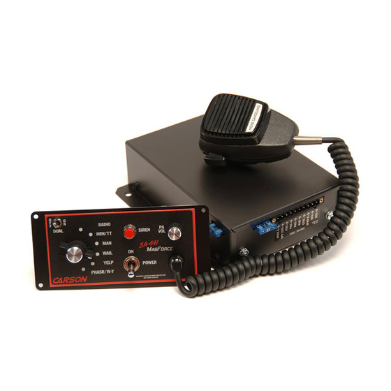
Page 4 of 16 SA-441-10 Installation and Operating Instructions GENERAL DESCRIPTION The SA-441 Dual Siren Amplifier is a premium unit designed for dual 100W speaker use. The control head is only 1 inch deep and can be installed in minimum clearance areas. Connection between the control head and amplifier is via a single lead wire with common ground. -
Page 5: Installation
SA-441-10 Installation and Operating Instructions Page 5 of 16 INSTALLATION Proper installation of the unit is essential for years of safe, reliable operation. Please read all instruc- tion before installing the unit. Failure to follow these instructions can cause serious damage to the unit or vehicle and may void warranties. -
Page 6: Option Switches
Page 6 of 16 SA-441-10 Installation and Operating Instructions OPTION SWITCHES An 8-position DIP switch on the remote amplifier may be changed to select various options. Option Switches On Remote Amp Option Switches Default Setting Shown (Switch 6 is ON) SW-1 Two-Tone - Turn this switch on to replace Phaser tone with Two-Tone. -
Page 7: Mounting - Amplifier
SA-441-10 Installation and Operating Instructions Page 7 of 16 MOUNTING – Amplifier Select a location for the amplifier in an area such as the driver compartment firewall, under a seat, etc. Mounting the amplifier in the engine compartment or in an area directly exposed to weather is not recommended. -
Page 8: Electrical Connections - Amplifier
Page 8 of 16 SA-441-10 Installation and Operating Instructions ELECTRICAL CONNECTIONS - Amplifier Electrical connections to the amplifier are made using a terminal block plug located on the amplifier. A label on the unit identifies each terminal function. You should install the plug on the unit before wiring. If the unit needs service the plug can be easily removed without unwiring. -
Page 9: Electrical Connections Continued
SA-441-10 Installation and Operating Instructions Page 9 of 16 ELECTRICAL CONNECTIONS CONTINUED HORN RLY Horn Vehicle Momentary +VDC Auxiliary Input Circuit Horn SPST Connection Switch -VDC Examples Splice +VDC May need to Added add diode Aux input is SPDT -VDC (10mA current) activated with Switch... -
Page 10: Operation
Page 10 of 16 SA-441-10 Installation and Operating Instructions OPERATION Sound Hazard - Sound level from siren speaker (>120dBA @ 10 feet) may cause hearing damage. Do not operate siren without adequate hearing protection for you and anyone in immediate vicinity. (Ref. -
Page 11: Microphone (Pa Override)
SA-441-10 Installation and Operating Instructions Page 11 of 16 MICROPHONE (PA Override) The noise-canceling microphone is used for public address operation and overrides any function when the push-to-talk button on the side of the microphone is pressed. PA VOL This control adjusts the PA volume. With the vehicle parked, set the PA vol- ume to the maximum level with no feedback (squeal). -
Page 12: Service
Page 12 of 16 SA-441-10 Installation and Operating Instructions SERVICE This unit is designed to provide years of reliable service under even the worst conditions. Many times there may appear to be a problem with the unit when the true problem is in the speaker(s) or improper installation. -
Page 13: Parts And Accessories
SA-441-10 Installation and Operating Instructions Page 13 of 16 PARTS and ACCESSORIES The following parts and accessories are available from Carson Manufacturing Company, Inc.: Part Description CP5018 Button, Switch Cap Red (for Siren pushbutton) CP4732 Control, 1K Vertical Trimmer (Amplifier) -
Page 14: Return
SA-441-10 Installation and Operating Instructions RETURN If you have any questions concerning this or any other Carson product, please contact our Technical Service Department at (888) 577-6877. Many issues can be handled over the phone. We can also be reached via e-mail at service@carsonsirens.com If a product must be returned for any reason, please contact our Technical Service Department to obtain a Returned Merchandise Authorization number (RMA#) before you ship the product to Carson. -
Page 15: Control Head Installation Template
CONTROL HEAD INSTALLATION TEMPLATE 6-1/4” 5-7/8” 5-1/4” 1/2” 2-1/2” This inner area to be removed. 2-5/8” 2-7/8” 1/8” CAUTION: Please note that top and bottom edges only provide 1/8” overlap. Cut carefully. - Page 16 Page 16 of 16 SA-441-10 Installation and Operating Instructions BLANK PAGE 11/1/19 CP5203A...
Need help?
Do you have a question about the SA-441-10F and is the answer not in the manual?
Questions and answers