Table of Contents
Advertisement
Quick Links
E
S
INPUT LEVEL dB
(
)
POWER
-24
-12
0
+6
0
-6
+9
UNiK A
OUT
-20
+12
IN
-20
∞
dB
+15
MAIN LINK
SPLITTER
MAIN INPUT LEVEL
MAIN OUTPUT LEVEL
I N
T
R
C T
S
U S E R
I N S T R U C T I O N S
This booklet contains important information concerning the proper and safe operation of your new amplifier.
R
OUTPUT LEVEL dB
(
)
INPUT OUTPUT LEVEL dB
(
)
INPUT OUTPUT LEVEL dB
1
-24
-12
0
+6
-24
-18
-12
-6
0
+6
+12
+18
-24
-18
0
0
SPLITTER
SPLITTER
-6
+9
-6
+9
MIXER
MIXER
+12
-20
+12
-20
∞
∞
dB
+15
dB
+15
LEFT
RIGHT
SPLIT/MIX
SPLIT/MIX
MIXER
BALANCE/PAN
LEVEL
U I
N
S
(
)
INPUT OUTPUT LEVEL dB
(
)
2
3
-12
-6
0
+6
+12
+18
-24
-18
-12
-6
0
+6
+12
+18
0
0
SPLITTER
-6
+9
-6
+9
MIXER
+12
-20
+12
∞
∞
+15
LEFT
RIGHT
+15
LEFT
RIGHT
dB
dB
SPLIT/MIX
BALANCE/PAN
BALANCE/PAN
LEVEL
LEVEL
O
UNiK A
P R O F E S S I O N A L A U D I O
MX-880
INPUT OUTPUT LEVEL dB
(
)
INPUT OUTPUT LEVEL dB
(
)
4
-24
-18
-12
-6
0
+6
+12
+18
-24
-18
-12
-6
0
+6
+12
0
0
SPLITTER
SPLITTER
-6
+9
-6
+9
MIXER
MIXER
-20
+12
-20
+12
∞
∞
+15
LEFT
RIGHT
+15
LEFT
dB
dB
SPLIT/MIX
SPLIT/MIX
BALANCE/PAN
BALANCE/PAN
LEVEL
LEVEL
INPUT OUTPUT LEVEL dB
(
)
5
6
+18
-24
-18
-12
-6
0
+6
+12
+18
0
MX-880
SPLITTER
-6
+9
PRO
8-CHANNEL
SPLITTER / MIXER
MIXER
-20
+12
∞
RIGHT
+15
LEFT
RIGHT
dB
SPLIT/MIX
BALANCE/PAN
LEVEL
i i i i
Advertisement
Table of Contents

Related Manuals for Unika MX-880


Summary of Contents for Unika MX-880
- Page 1 UNiK A P R O F E S S I O N A L A U D I O MX-880 INPUT LEVEL dB OUTPUT LEVEL dB INPUT OUTPUT LEVEL dB INPUT OUTPUT LEVEL dB INPUT OUTPUT LEVEL dB INPUT OUTPUT LEVEL dB...
-
Page 2: Detailed Safety Instructions
UNiKA MX-880 SAFETY INSTRUCTIONS Http://www/unika.com.tw CAUTION This symbol, wherever it appears, alerts RISK OF ELECTRIC SHOCK you to the presence of uninsulated DO NOT OPEN dangerous voltage inside the enclosure - voltage that may be sufficient to constitute a risk of shock. - Page 3 Ultra-wide bandwidth from 2 Hz to 200 kHz for “open” sound The MX-880 offers 6 mono inputs, 6 mono outputs, 2 main inputs and 2 main outputs A Main Link switch allows you to route the Main Input to the Main Output to link several units ...
- Page 4 Sleeve= converted into studio levels (+4 dBu), and vice versa. Ground/Shield Ground/Shield 1.1 Typical applications The MX-880 is one of the most flexible systems of its type. The following applications can be realized: Ring Sleeve Sleeve 2 IN/8 OUT splitter, 8 IN/2 OUT mixer, 6 IN/6 OUT matching amplifier or any other combination.
-
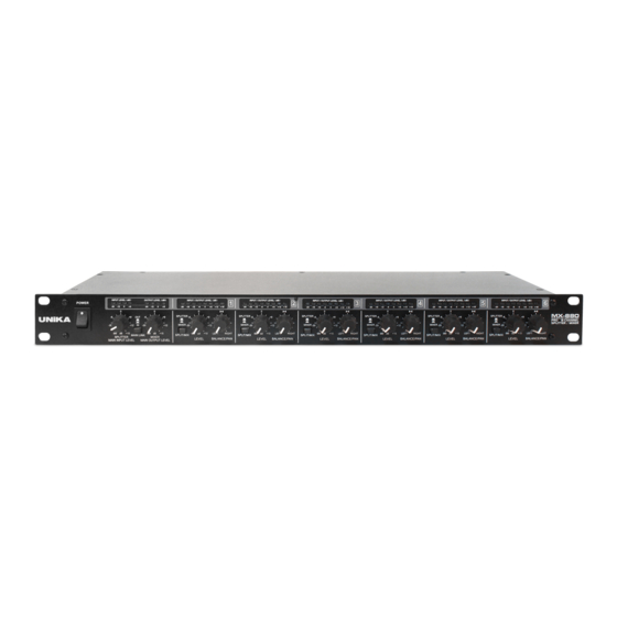
Page 5: The Front Panel Control Elements
Fig. 2: MX-880 front panel The Unika MX-880 has six identical channels. Each channel is equipped with two rotary controls, one button and eight LEDs. Moreover there is a main section with two rotary controls, one button and eight LEDs. - Page 6 (or a combination of both). MAIN INPUTS. These are the main audio inputs of your MX-880, available as balanced XLR connectors. They may feed the mono outputs of all channels which are operated in SPLIT mode.
-
Page 7: Block Diagram
Applications Specifications 3.BLOCK DIAGRAM Fig. 3.1: Block diagram of the Unika MX-880 MAIN Section Both main inputs interface via the MAIN INPUT LEVEL control with the input bus as well as with the main outputs. The MAIN OUTPUT LEVEL control determines the output level of the signals which are summed by the second bus (i.e., the output bus) and are subsequently routed to the main outputs. -
Page 8: Application As A Mixer
In this mode, the individual signal sources are connected to the mono inputs on the UNIKA MX-880. Each channel has a LEVEL knob to control the amount of its signal relative to others in the main section. - Page 9 In this mode, the output signal from the mixer is applied to the main inputs of the UNIKA MX-880. If the SPLIT/MIX switches are set to “SPLIT”, the mono outputs of the respective channels provide either the left or the right main signal.
-
Page 10: Application As A Matching Amplifier
Fig. 4.3: Block diagram of the MATCHING AMPLIFIER function The Unika MX-880 can also be used as a multiple matching amplifier. The task of a matching amplifier is to convert the level of a signal source into another level. For instance, a CDR or MD recorder with home recording level (-10 dBV) can be raised to studio level (+4 dBu). - Page 11 UNiKA MX-880 Http://www/unika.com.tw Specifications Introduction C o n t r o l e l e m e n t s Block Diagram Applications 5.SPECIFICATIONS AUDIO INPUTS Connectors XLR and 1/4" TRS Type RF filtered, servo-balanced input Impedance 50 kOhms balanced, 25 kOhms unbalanced...
- Page 12 UNiK A P R O F E S S I O N A L A U D I O...
Need help?
Do you have a question about the MX-880 and is the answer not in the manual?
Questions and answers