Table of Contents
Advertisement
Quick Links
Advertisement
Table of Contents

Summary of Contents for Renogy DCC-1212 Series
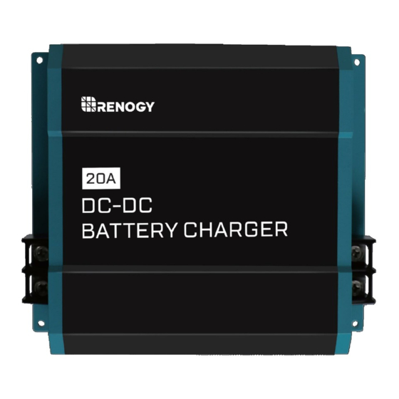
- Page 1 DC-DC On Board Battery Charger DCC1212-20-40...
- Page 2 Charger. Do NOT operate the battery charger until you have read and understood the contents of this manual. Renogy recommends that the charger be installed by a qualified professional. The following symbols are used throughout the manual to indicate potentially dangerous conditions or important safety information.
-
Page 3: Product Overview
Product overview Identification of Parts Alternator / Starter Battery Input Side Output / House Battery Side... - Page 4 Positive (+) Output Terminal for House Battery Output (-) Negative (-) Output Terminal for House Battery Package Includes DCDC Battery Charger Manual Please Note: Please Note: You will find the most up to date manual at www.renogy.com under the download section.
-
Page 5: Installation
Sensor measures temperature at the battery, allowing the DC- DC charger to use this data for accurate temperature compensation and charge voltage adjustment. Improve your battery charging system with a Renogy Temperature Sensor. No temperature compensation when charging lithium battery. - Page 6 When selecting a location for the DCDC, make sure that the unit is as close as possible to the battery you will be charging (auxiliary battery). The charger may be mounted on the cabin of the vehicle, along a chassis rail, the inner guard of a vehicle, behind the grille or headlight or even on the side of the radiator.
- Page 7 Figure 2 Cable Cross Section *The following is a reference and may not cover all the unique applications that may exist. Consult your installer for further questions. Important Note: When the battery charger is sending full amps, the input side will experience a higher draw.
- Page 8 Connecting the Battery Charger The DCDC will not turn on without a D+ ignition cable. When connected, the DCDC will turn on when the ignition is on. This means that even if your engine is not on, the starter battery will immediately be used to power the DCDC and start charging the house battery.
- Page 9 Important Note: The Alternator will not be connected directly to the input of the DCDC. The alternator must be connected to the starter battery and from this connection there will be a bus connection to the input of the DCDC. See Figure 3 Figure 3 Figure 4 3.
-
Page 10: Operation
Caution: The DCDC will turn on when the ignition is on. This means that even if your engine is not on, the starter battery will immediately be used to power the DCDC and start charging the house battery. It is recommended to have the vehicle completely on. IMPORTANT: A D+ ignition cable is required to turn the unit on. - Page 11 Setting Battery Charger Please Note: The battery charger is for lithium-iron phosphate battery types with a built in BMS system. Do not use the device under any circumstances to charge other types of batteries (ex. NiCd, NiMH, etc.). WARNING: Danger of Explosion! *Note: Check the charging requirements from the battery manufacturer before charging your battery with this unit.
- Page 12 SW5 ON If SW5 is set to ON, then you will follow the lead acid charging profiles in the following charts. SW1/SW2 will determine the desired absorption voltage and SW3/SW4 will determine the desired float voltage. *Please note that the charging profile will automatically bulk before approaching the user-defined absorption and float stage.
- Page 13 SW5 OFF Please Note: The battery charger is for lithium-iron phosphate battery types with a built in BMS system. Do not use the device under any circumstances to charge other types of batteries (ex. NiCd, NiMH, etc.). If SW5 is set to OFF, then you will follow the lithium-iron phosphate charging profiles in the following charts.
- Page 14 Although the LC terminal is in the output side, this will be connected to the INPUT Alternator/Starter Battery common positive.
- Page 15 The manufacturer accepts no liability for damage in the following cases: • Faulty assembly or connection • Damage to the product resulting from mechanical influences and excess voltage • Alterations to the product without expressed permission from the manufacturer • Use for purposes other than those described in the operating manual...
- Page 16 Do not open the device. You risk exposing yourself to an electric shock by doing this. If you have detailed questions about the battery charger, please contact our customer support (addresses on the back of the instruction manual). Behavior Troubleshoot Steps Green LED not turning on, 1.
-
Page 17: Protective Function
Protection Function / Fixes LED is Red, what do I do? Protective Function Potential Fixes Over-Voltage Protection; 1. Use a multi-meter to check the voltage of the battery bank to Under-Voltage Protection confirm whether the starter battery or house battery is above specification (16V) or below the specification (8V) 2. -
Page 18: Technical Specifications
Technical Specifications DCC-1212-20 DCC-1212-40 DCC-1212-60 Transformation 12VDC -> 12VDC Nominal Input Voltage 12 VDC Input Voltage Range 8V ~ 16VDC Rated Charging Current Charging Voltage 13.2V – 14.7V, depending on DIP Switch Range Max Rated Output 250W 500W 750W Power Residual ripple of <... - Page 19 Protective Function Specifications @ Input High-Voltage, low-voltage, reverse polarity, high- temperature, short-circuit Low Voltage cut-out Low-voltage restart High-voltage shutdown High-voltage restart 15.5V...


Need help?
Do you have a question about the DCC-1212 Series and is the answer not in the manual?
Questions and answers