
Related Manuals for Renogy PWM1020CC-DB


Summary of Contents for Renogy PWM1020CC-DB
- Page 1 Duo Battery Charge Controller RENOGY 10A | 20A Pulse Width Modulation Solar Charge Controller Manual 2775 E. Philadelphia St., Ontario CA 91761 1-800-330-8678...
-
Page 2: Important Safety Instructions
There are no serviceable parts for this controller. Do disassemble or attempt to repair the controller. Disconnect the solar module and fuse/breakers near to battery before installing or adjusting the PWM1020CC-DB. Install external fuses/breakers as required. allow water to enter the controller. -
Page 3: Battery Safety
Battery Safety Use only sealed lead-acid, flooded, or gel batteries which must be deep cycle. Explosive battery gases may be present while charging. Be certain there is enough ventilation to release the gases. Be careful when working with large lead acid batteries. Wear eye protection and have fresh water available in case there is contact with the battery acid. -
Page 4: Table Of Contents
Table of Contents General Information ............................5 Optional Components ............................ 6 Identification of Parts ............................. 7 Installation ................................8 Operation ................................13 Troubleshooting ............................. 15 Maintenance ..............................15 Fusing ................................... 15 Technical Specifications ........................... 16 Dimensions ................................ 17 Wiring Diagrams ............................. 18... -
Page 5: General Information
General Information The Renogy PWM1020CC-DB features dual battery charging capability making it great for RVs, caravans, and boats. With its advanced PWM charging technology, your batteries will be protected from discharging and over-charging. This controller is specifically designed for mobile off-grid applications supporting 12V deep cycle battery varieties such as sealed lead acid, gel, and flooded. -
Page 6: Optional Components
Optional Components *The PWM10A/20A-Dual Battery charge controller is shipped by itself, without any additional components. Optional components that require a separate purchase: Remote Temperature Sensor (TS-R): Measures the temperature at the battery and uses this data for very accurate temperature compensation. -
Page 7: Identification Of Parts
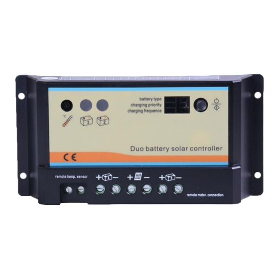
Identification of Parts Figure 3 Key Parts 1. Local Temp. Sensor—Measures ambient temperature. Battery regulation is adjusted accordingly. 2. Batt #1 status LED—Provides charging & battery status and errors 3. Batt #2 status LED—Provides charging & battery status and errors 4. -
Page 8: Installation
There should be at least 100mm of clearance above and below the controller to allow for cooling. If mounted in an enclosure, ventilation is highly recommended. WARNING: Risk of explosion! Never install the PWM1020CC-DB in a sealed enclose with flooded batteries! Do not install in a confined area where battery gas can accumulate. Step 1:... - Page 9 Wiring Recommended tools to have before installation: Flathead Screwdriver Multi-Meter WARNING: Connect battery terminal wires to the charge controller FIRST then connect the solar panel(s) to the charge controller. NEVER connect solar panel to charge controller before the battery. CAUTION: Do not over-torque or over tighten the screw terminals.
- Page 10 Battery Connect Battery 1: Refer to Figure 4, Connect the negative terminal of Battery 1 to the negative terminal of the charge controller under the Battery 1 logo. Then connect the positive terminal of Battery 1 to the positive terminal of the charge controller under the Battery 1 logo. Connect Battery 2: Repeat the process described in last step for Battery 2.
- Page 11 Solar Panels Connect the solar panel(s): Connect the negative PV lead of the solar panel to the negative terminal of the charge controller under the solar array logo. Then connect the positive lead of solar to the positive terminal of the charge controller under the solar array logo. Make sure the solar module(s) voltage and current do not exceed the ratings of the charge controller.
- Page 12 Temperature Sensor (if applicable) Connect the Remote Temperature Sensor (Optional): If you purchased the remote temperature for your batteries, you can connect it in the remote temperature terminals depicted in Figure 4. If you are not planning on using this sensor, you can skip this step. Note: When the RTS is not present, the controller will calculate the data from the local temperature sensor.
-
Page 13: Operation
Operation Battery Type To select the battery type press the SET button on the controller a few times until the “Battery Type” LED lights up. Press the setting button again and hold it for 5 seconds until the digits start flashing. Press the setting button again to choose the battery type as described in Table 1. - Page 14 Number PWM Charging Frequency 25 Hz (pre-set) 50 HZ 100 HZ Table 3 Charging frequency settings Battery #1 Status LED Indicator Battery #2 Status LED Indicator Figure 5 Charge controller LED indicators Battery Indicators The LED indicator shown in Figure 5-2 will turn on whenever sunlight is available for battery charging.
-
Page 15: Troubleshooting
Troubleshooting Check all connections to ensure they are secure and clean Check polarity of the battery connection and make sure the battery generates at least 6V Ensure the solar panels are exposed to sufficient light – ideally position them to face the sun directly ... -
Page 16: Technical Specifications
Fuse from Solar Panel(s) to Controller Ex. 200W; 2 X 100 W panels Series: Total Amperage = I = 5.75A * 1.56 Fuse = minimum of 5.75A * 1.56 = 8.97A = 9A fuse Parallel Total Amperage = I = (5.75A + 5.75A) * 1.56 Fuse = minimum of 11.5 * 1.56 = 17.94 = 18A fuse Technical Specifications Charge Controller... -
Page 17: Dimensions
Dimensions Note: All dimensions are in inches... -
Page 18: Wiring Diagrams
Wiring Diagrams 100W Wiring Diagram 1. Solar Panel 2. Fuse 3. Adapter Kit 4. Charge Controller (10A/20A), 5. Tray Cable 6. Battery Bank (12V) - Page 19 200W Wiring Diagram—Series 24V Battery Bank 1. Solar Panels 2. Fuse 3. Adapter Kit 4. Charge Controller (10A/20A), 5. Tray Cable 6. Battery Bank (24V)
- Page 20 200W Wiring Diagram—Parallel 12V Battery Bank 1. Solar Panels 2. MC4 Branch Connectors 3. Fuse 4. Adapter Kit 5. Charge Controller (20A) 6. Tray Cable 7. Battery Bank (12V)
- Page 21 300W Wiring Diagram—Parallel 24V Battery Bank 1. Solar Panels 2. MC4 Branch Connectors 3. Fuse 4. Adapter Kit 5. Charge Controller (20A) 6. Tray Cable 7. Battery Bank (24V) Updated: July 30, 2015...
Need help?
Do you have a question about the PWM1020CC-DB and is the answer not in the manual?
Questions and answers