
Related Manuals for Audiotec Fischer Match M 5DSP MK2 micro


Summary of Contents for Audiotec Fischer Match M 5DSP MK2 micro
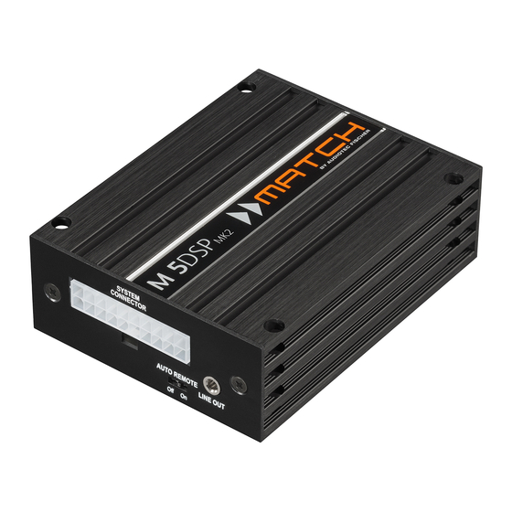
- Page 1 M 5DSP micro 5-Kanal Miniatur-Verstärker mit integriertem DSP 5-Channel miniature amplifier with integrated DSP...
-
Page 2: Herzlichen Glückwunsch
Viel Freude an diesem Produkt wünscht Ihnen das profitieren Sie als Kunde direkt von unserer mehr Team von als 30-jährigen Erfahrung in der Forschung und Entwicklung von Audiokomponenten. AUDIOTEC FISCHER Allgemeine Hinweise Allgemeines zum Einbau von MATCH-Kompo- auch in der doppelten Wandverkleidung verbergen nenten können. -
Page 3: Anschluss- Und Bedienelemente
Anschluss- und Bedienelemente System Connector Line Out Anschluss für den MATCH Kabelbaum. Stereo-Vorverstärkerausgang Verwenden Sie ausschließlich ein MATCH schluss weiterer Verstärker. Zum Einschalten Original-Anschlusskabel, um den Verstärker dieser Verstärker muss der Remote-Ausgang mit dem Autoradio zu verbinden. (Remote Out) verwendet werden. Auto Remote Dient zum Aktivieren bzw. -
Page 4: Subwoofer Output
Inbetriebnahme und Funktionen 1 System Connector schlusskabel zum Anschluss weiterer Verstärker zu Diese Buchse dient zum Anschluss des mitgeliefer- verwenden. ten Kabelbaums. Verwenden Sie zur Verbindung 4 Subwoofer Output des MATCH M 5DSP MK2 mit dem Originalradio ausschließlich den mitgelieferten Kabelbaum oder Diese Buchse dient zum Anschluss eines passiven eine Alternative aus dem MATCH Zubehörpro- MATCH Plug &... -
Page 5: Status Led
an. Wenn Sie längere Distanzen zu überbrü- wiedergeben, bis ein neues Sound Setup einge- cken haben, verwenden Sie bitte eine aktive spielt wurde. USB-Verlängerung mit integriertem Repeater 7 Remote In / Out oder das optional erhältliche WIFI CONTROL Interface. Remote In: Der Remote-Eingang dient zum Ein- 3. -
Page 6: Control Input
Inbetriebnahme und Funktionen 9 Optical Input Control Input Optischer Eingang im SPDIF-Format für den An- Dieser Multifunktionsanschluss dient zum An- schluss an Signalquellen mit digitalem Ausgang. schluss von MATCH Zubehörprodukten, wie bei- Die „Sampling Rate“ dieses Eingangs muss zwi- spielsweise einer Fernbedienung mit deren Hilfe schen 12 - 96 kHz liegen. - Page 7 Umschaltung der Leistungsmodi HighPower- / MidPower-Modus Im folgenden Abschnitt nun die wichtigsten Schritte zur Aktivierung des „HighPower“-Modus: Die M 5DSP MK2 verfügt über zwei Leistungsmodi, 1. Schließen Sie den Verstärker mit dem bei- den „HighPower“-Modus für maximale Performance “MidPower”-Modus reduzierter liegenden USB-Kabel an den Computer an.
- Page 8 Einbau und Installation Abb. 1: Pinbelegung System Connector SYSTEM CONNECTOR AUTO REMOTE LINE OUT Highlevel-Lautsprechereingang hinten links (-) Highlevel-Lautsprechereingang hinten links (+) Highlevel-Lautsprechereingang vorne links (-) Highlevel-Lautsprechereingang vorne links (+) Highlevel-Lautsprechereingang vorne rechts (-) Highlevel-Lautsprechereingang vorne rechts (+) Highlevel-Lautsprechereingang hinten rechts (-) Highlevel-Lautsprechereingang hinten rechts (+) Lautsprecherausgang hinten rechts (-) Lautsprecherausgang hinten rechts (+)
- Page 9 Der MATCH M 5DSP MK2 Verstärker wird wie darf 4 Ohm nicht unterschreiten, da sonst die nachfolgend beschrieben an das Autoradio Schutzschaltung des Verstärkers aktiviert wird. angeschlossen. Achtung: Für die Durchführung der nachfolgenden 3. Anschluss einer digitalen Signalquelle Schritte werden Spezialwerkzeuge und Fachwis- Sofern Sie über eine Signalquelle mit op- sen benötigt.
- Page 10 Einbau und Installation len wir einen Querschnitt von min. 6 mm². 2. Anschließend verbinden Sie den 2-poligen Das Massekabel (schwarz / gleicher Quer- Molex Stecker des Subwooferkabels mit dem schnitt wie das +12 V Kabel) muss an einem Subwoofer Output des Verstärkers. blanken, von Lackresten befreiten Massepunkt des Kfz-Chassis oder direkt an dem Minuspol der Autobatterie angeschlossen werden.
- Page 11 Anschluss mit Hilfe des PP-ISO Kabels Um die Installation des M 5DSP MK2 an ein Werks- 4a. Stromversorgung über den Kabelbaum des oder Nachrüstradio deutlich zu vereinfachen, Fahrzeugs: kann der Verstärker auch mit Hilfe eines optional Die Stromversorgung des Verstärkers wird über erhältlichen PP-ISO Kabels (2,2 m Version - den PP-ISO Kabelbaum direkt vom Originalka- Art.
- Page 12 Anschluss mit Hilfe des PP-ISO Kabels kabels an das Bordnetz muss die Autobat- Hinweis: MOST-Bus terie abgeklemmt werden. Das +12 V Strom- Bei einigen Fahrzeugen kann es notwendig sein, die kabel (gelb Abb. 4 / min. 4 mm²) ist am Lichtleiterverbindung aus dem Original-Radioan- Pluspol der Batterie anzuschließen.
- Page 13 Abb. 4: Direkte Stromversorgung – Voraussetzung für Betrieb im „HighPower“-Modus Diese Seite des Kabelbaums wird direkt an die Batterie angeschlossen. Dafür werden die dafür vorgesehenen Steckverbinder des Kabelbaums getrennt. Gelbe Leitung: +12 Volt Leitung zum Anschluss an den Pluspol der Autobatterie. Schwarze Leitung: Masse-Leitung zum Anschluss an den Minuspol der Autobatterie oder zum An- schluss an einen Massepunkt des Kfz-Chassis.
- Page 14 Konfigurationshinweise für die DSP-Soundeffekte Der MATCH M 5DSP MK2 Verstärker bietet ein- zigartige DSP-Sound effekte wie das „Augmen- ted Bass Processing“, den „StageXpander“, den „ RealCenter“ und mehr. Um in den Genuss der DSP-Soundeffekte zu kom- men, müssen in der DSP PC-Tool Software Einstel- lungen im IO- und FX-Menü...
- Page 15 Signalrouting F & G: 5. Abschließend legen Sie noch durch Setzen eines Hakens fest, auf welchen Ausgangskanal bzw. welche Ausgangskanäle sich das Bass Processing auswirken soll. 3. Wiederholen Sie das Routing für alle genutzten Routing-Matrizen. 4. Wechseln Sie nun in das FX-Menü und aktivie- ren den gewünschten Soundeffekt durch Setzen eines Hakens.
-
Page 16: Technische Daten
Technische Daten Ausgangsleistung RMS / Max. - @ 4 Ohm (Front / Rear Kanäle) ........4 x 60 / 120 Watt (HighPower-Modus) 4 x 35 / 70 Watt (MidPower-Modus) - Subwooferausgang an 4 Ohm……………………………1 x 90 / 180 Watt (High- & MidPower-Modus) - Subwooferausgang an 2 Ohm……………………………1 x 160 / 320 Watt (High- &... -
Page 17: General Instructions
MATCH M 5DSP MK2. Thanks to more than 30 years of experience in research and development of audio products this amplifier sets new standards in the range of digital Yours, amplifiers. AUDIOTEC FISCHER General instructions General instructions connecting General installation instructions for MATCH... - Page 18 Connectors and control units System Connector Line Out Connector for the MATCH cable harness. Stereo pre-amp output for connecting ex- Make sure that you only use the original ca- ternal amplifiers. Make sure that the remote ble that comes with the amplifier to connect output (Remote Out) is used to turn on these the M 5DSP MK2 with your car radio.
-
Page 19: Usb Input
Initial start-up and functions 1 System Connector or center speaker. Use only the enclosed subwoof- Please use this terminal only in combination with er cable for connecting a speaker. When using a the cable harness that is included in delivery or an subwoofer, we strongly recommend to connect the appropriate cable from the MATCH accessories M 5DSP MK2 directly to a 12 Volt source. -
Page 20: Initial Start-Up And Functions
Initial start-up and functions 8 Status LED ume of you car radio to minimum position during first start-up. Additionally no device should be con- The Status LED indicates the operating mode of the nected to the Line Out until general settings in the amplifier and of the DSP memory. - Page 21 Unique Features of the M 5DSP MK2 ACO – Advanced 32 Bit CoProcessor Smart highlevel input ADEP.3 The MATCH M 5DSP MK2 amplifier incorporates Modern, factory-installed car radios incorporate so- an extraordinary powerful 32 Bit CoProcessor of phisticated possibilities of diagnosing the connect- ed speakers.
-
Page 22: Switching Between The Two Power Modes
Switching between the two power modes HighPower / MidPower mode In the following the most important steps how to ac- tivate the “HighPower” mode are described: The M 5DSP MK2 has two power modes – the 1. Connect the amplifier to your computer using “HighPower”... -
Page 23: Installation
Installation Fig. 1: Pin configuration of the system connector SYSTEM CONNECTOR AUTO REMOTE LINE OUT Highlevel loudspeaker input rear left (-) Highlevel loudspeaker input rear left (+) Highlevel loudspeaker input front left (-) Highlevel loudspeaker input front left (+) Highlevel loudspeaker input front right (-) Highlevel loudspeaker input front right (+) Highlevel loudspeaker input rear right (-) Highlevel loudspeaker input rear right (+) - Page 24 Installation The MATCH M 5DSP MK2 must be connected to standard configuration MATCH the head unit (car radio) as follows: M 5DSP MK2 automatically activates the digital input if a digital audio signal is detected. This Caution: Carrying out the following steps will re- function can be deactivated via the DSP PC- quire special tools and technical knowledge.
- Page 25 i.e. an area which has been cleaned of all paint Connecting a conventional passive subwoofer residues. or center speaker: 1. Disconnect the ASIA plug connection of the 5. Connecting the remote input subwoofer cable (C). The remote input (Remote In) has to be con- nected to the remote output of the signal source if the signal source which is connected to the highlevel inputs is not activating the “automatic...
-
Page 26: Installation With Pp-Iso Cable
Installation with PP-ISO cable To simplify installation to an OEM or aftermarket first. If fuse rating is lower than 20 A then we radio the M 5DSP MK2 can also be connected strongly recommend option 4b. Note: Depending on the vehicle type the con- using the optional PP-ISO cable (2.2 m version, nections for switched (ACC+) positive ter- art. - Page 27 You can now reconnect the car battery. If one the original car radio connector and insert it into of the cable extensions PP-EC 11, PP-EC 25 the car radio connector of the MATCH cable har- ness which has a dedicated recess for this. or PP-EC 40 will be used, the separate power supply has to be connected to the extension cable.
- Page 28 Installation with PP-ISO cable Fig. 4: Direct power supply – requirement for operating in “HighPower” mode This side of the cable harness will be directly connected to the car´s battery. Therefore you have to separate intended cable joints of the harness. Yellow wire: +12 Volts wire for connecting the M 5DSP MK2 to the positive terminal of the car´s battery.
- Page 29 Configuration notes for the DSP sound effects The MATCH M 5DSP MK2 offers unique DSP Configuration of the Front Processing with its sound effects like “Augmented Bass Processing”, functions StageXpander and ClarityXpander “ StageXpander”, “RealCenter” and many more. In Normally, the settings of the StageXpander and order to enjoy the DSP sound effects, specific set- Front ClarityXpander only affect the output channels tings have to be made in the IO and FX menu of the...
- Page 30 Configuration notes for the DSP sound effects 5. Finally, determine the output channel / output channels on which the Augmented Bass Pro- cessing should be applied by placing a tick. ACO platform features Beside the unique DSP sound effects the ACO plat- internal memory locations, the optionally available form of the MATCH M 5DSP MK2 provides a bunch DIRECTOR display remote control or the HELIX...
-
Page 31: Technical Data
Technical Data Output power RMS / max. - @ 4 Ohms (Front / Rear channels) ....... 4 x 60 / 120 Watts (HighPower mode) 4 x 35 / 70 Watts (MidPower mode) - Subwoofer output @ 4 Ohms ........1 x 90 / 180 Watts (High- & MidPower mode) - Subwoofer output @ 2 Ohms ........1 x 160 / 320 Watts (High- &... - Page 32 Audiotec Fischer GmbH Hünegräben 26 · 57392 Schmallenberg · Germany Tel.: +49 2972 9788 0 · Fax: +49 2972 9788 88 E-mail: match@audiotec-fischer.com · Internet: www.audiotec-fischer.com...
Need help?
Do you have a question about the Match M 5DSP MK2 micro and is the answer not in the manual?
Questions and answers