Table of Contents

Related Manuals for Audiotec Fischer MATCH UP 10DSP


Summary of Contents for Audiotec Fischer MATCH UP 10DSP
- Page 1 UP 10DSP U P G R A D E 10-Kanal Upgrade-Verstärker mit integriertem 11-Kanal 64 Bit DSP für universelle Anwendungen 10-channel upgrade amplifier with integrated 11-channel 64 Bit DSP for universal applications...
-
Page 2: Herzlichen Glückwunsch
Viel Freude an diesem Produkt wünscht Ihnen das als Kunde direkt von unserer mehr als 30-jährigen Team von Erfahrung in der Forschung und Entwicklung von Audiokomponenten. AUDIOTEC FISCHER Allgemeine Hinweise Allgemeines zum Einbau von MATCH-Kompo- den. Achten Sie bitte darauf, dass sich solche Teile nenten auch in der doppelten Wandverkleidung verbergen können. -
Page 3: Anschluss- Und Bedienelemente
Anschluss- und Bedienelemente REM IN / OUT Speaker Output E - J Anschluss für den Remote-Ein- und Aus- Lautsprecherausgänge der Kanäle E - J zum gang. Der Remote-Ausgang muss in jedem Anschluss von Lautsprechersystemen. Fall zur Einschaltung weiterer Verstärker ge- Highlevel Input E - H nutzt werden. - Page 4 Punkt 4; Einstellung der Eingangsempfindlichkeit). Achtung: Es wird dringend empfohlen, vor der er- Achtung: Verwenden Sie zur Verbindung der MATCH UP 10DSP mit dem Originalradio aus- sten Inbetriebnahme mit der DSP PC-Tool Software die grundlegenden Einstellungen im Verstärker vor- schließlich den mitgelieferten Kabelbaum oder eine zunehmen.
-
Page 5: Optical Input
9 SCP (Smart Control Port) sene Verstärker einzuschalten! Dieser Multifunktionseingang dient zum Anschluss 5 +12 V von MATCH Zubehörprodukten, wie beispielsweise Anschluss für das +12 V Versorgungskabel. Das einer Fernbedienung, mit deren Hilfe diverse Funk- Kabel ist am Pluspol der Batterie anzuschließen tionen des Verstärkers gesteuert werden können. -
Page 6: Status Led
Inbetriebnahme und Funktionen Status LED des / der angeschlossenen Verstärker/s zu ver- wenden, da ansonsten Störgeräusche auftreten Die Status LED zeigt den Betriebszustand des können. Verstärkers und dessen DSP-Speichers an. Der Remote-Ausgang schaltet sich automatisch Grün: Verstärker eingeschaltet und betriebsbereit. während des Power Save Modus sowie bei einem Orange: Power Save Modus aktiv. - Page 7 Einbau und Installation Abb. 1: Übersicht Anschlusskabel System Connector Anschlusskabel Speaker Output E - J Anschlusskabel Highlevel Input E - H Anschlusskabel Remote (REM IN / OUT) Anschlusskabel Abb. 2: Belegung Power Input Stecker +12 V – Zum Anschluss des +12 V Versorgungskabels. GND –...
- Page 8 Einbau und Installation Abb. 3: Pinbelegung UP 10DSP SPEAKER HIGHLEVEL SYSTEM OUTPUT INPUT CONNECTOR POWER INPUT +12V System Connector Highlevel-Lautsprechereingang hinten links (-) / C Highlevel-Lautsprechereingang hinten links (+) / C Highlevel-Lautsprechereingang vorne links (-) / A Highlevel-Lautsprechereingang vorne links (+) / A Highlevel-Lautsprechereingang vorne rechts (-) / B Highlevel-Lautsprechereingang vorne rechts (+) / B Highlevel-Lautsprechereingang hinten rechts (-) / D...
- Page 9 Der MATCH UP 10DSP Verstärker wird wie nach- den meisten Lautsprechern gekennzeichnet. folgend beschrieben montiert und angeschlos- Die Impedanz pro Kanal darf 4 Ohm nicht unterschreiten, da sonst die Schutzschal- sen. tung des Verstärkers aktiviert wird. Achtung: Für die Durchführung der nachfolgenden...
- Page 10 Einbau und Installation bedeutet, dass an sämtlichen Ausgängen der UP 10DSP der volle Pegel anliegt. Dies kann im Extremfall die angeschlossenen Lautsprecher zerstören. Wir raten deshalb dringend dazu, eine optionale Fernbedienung zur Einstellung der Lautstärke der digitalen Signaleingänge zu verwenden! Hinweis: Die UP 10DSP kann nur unkompri- mierte, digitale Stereo PCM-Signale mit einer Abtastrate zwischen 12 kHz und 96 kHz ver-...
- Page 11 5. Erhöhen Sie die Eingangsempfindlichkeit bis die Clipping Anzeige aufleuchtet. Schieben 7. Konfiguration des Remote-Eingangs Sie nun den Regler zurück bis die Clipping Die Einschaltung der MATCH UP 10DSP er- Anzeige wieder erlischt. folgt automatisch bei Ansteuerung über die Hochpegel-Lautsprechereingänge oder sobald ein Remote-Signal am Remote-Eingang (REM IN) anliegt.
- Page 12 Einbau und Installation Eingang belegt werden. Um die automatische mit der Kfz-Masse (Fahrzeugkarosserie). Die- Einschaltung zu deaktivieren, stellen Sie den ses kann Ihren Verstärker zerstören. Achten Sie Auto Remote Schalter auf die Schalterstellung darauf, dass alle Lautsprechersysteme phasen- richtig angeschlossen sind, d.h. Plus zu Plus „Off“.
- Page 13 Einstellungsbeispiele für die Eingangsempfindlichkeit der Kanäle G & H: Quelle Jumper position Input Gain im DSP PC-Tool OEM-Radio Low Voltage Range (J 1) – Werkseitige Jumperposition Bis 25 Watt Sinusleistung pro Kanal an 4 Ohm bzw. bis 50 Watt Sinuslei- (siehe Abb.
- Page 14 Konfigurationsbeispiele Beispiel 1: Kanalrouting mit Virtual Channel Processing 4-Kanal Headunit > Vorne: 3-Wege vollaktiv; Hinten: 2-Wege vollaktiv + Line Out für externen Subwoofer Vom Autoradio Eingänge Virtuelle Kanäle Ausgänge Zu den Lautsprechern Amp Out A Front L High – Hochtöner VL Front L Full (A) Amp Out C Front L Mid –...
- Page 15 Beispiel 3: 9-Kanal 1 zu 1 Kanalrouting (IOR) z.B. bei Mercedes Burmester oder BMW Harman Kardon mit den optionalen MATCH UPGRADE Kabelbäumen – Nur in Verbindung mit dem optionalen MEC ANALOG IN Modul Vom Werks- Eingänge Ausgänge Zu den Lautsprechern verstärker Front L Full Input A...
-
Page 16: Anschluss An Den Computer
Anschluss an den Computer Die MATCH UP 10DSP kann mit Hilfe der Im folgenden Abschnitt lesen Sie die wichtigsten DSP PC-Tool Software frei konfiguriert werden. Die Schritte zum Anschluss und der ersten Inbetrieb- Software stellt alle Funktionen übersichtlich und nahme: 1. - Page 17 Virtual Channel Processing (VCP) Das Bedienkonzept des VCP Im Gegensatz zu bisherigen Methoden ist das Virtual Channel Processing (VCP) ein mehrstufiges Signalverarbeitungs-Konzept, welches die perfekte Konfiguration komplexer Soundsysteme ermöglicht und somit ganz neue Möglichkeiten des Klangtunings eröffnet. Die Funktion erweitert den bisherigen Umfang des Gerätes um eine neue Ebene an prozessierten Kanälen, welche sich zwischen den Ein- und Ausgängen befindet.
- Page 18 Virtual Channel Processing (VCP) – Kanalübergreifender Gruppen-Equalizer Beispielanwendung: Aktives Mehrwege- System Wird ein Eingangssignal (bspw. Vorne links) erst auf einen virtuellen Kanal geroutet (Front L Full) und dieses Signal anschließend auf ein aktives Mehrwege-System geroutet (bspw. Vorne links – Hochtöner, Mitteltöner und Tieftöner), so ist es möglich, mit Hilfe des Equalizers des virtuellen Kanals alle nachgeschalteten einzelnen Kanäle gleichzeitig in ihrer Tonalität zu beeinflussen.
- Page 19 Konfiguration des Virtual Channel Processing (VCP) Um das VCP zu konfigurieren, muss zuerst das „Virtual Channel Processing“ im DCM-Menü der DSP PC- Tool Software eingeschaltet werden. Gehen Sie dazu in den „Virtual Channel Processing“-Tab und klicken auf die rechte Box mit der VCP-Grafik. Anschließend erfolgt die Konfiguration in drei Schritten – hier am Beispiel einer 3-Wege Konfiguration mit einem 2-Wege Eingangssignal erläutert.
- Page 20 Konfiguration des Virtual Channel Processing (VCP) Workflow-Schritt 2 – Ausgangsrouting Nachdem alle genutzten Eingangssignale in den jeweiligen Signal-Routing-Matrizen konfiguriert wurden, müssen die virtuellen Kanäle nun den physischen Ausgangskanälen zugeordnet werden. Hierbei kann ein virtuelles Signal (bspw. Front L Full) mehreren Ausgängen zugewiesen werden, wie beispielsweise dem vorderen linken Hochtöner, Mitteltöner und Tieftöner.
- Page 21 Kanals gleichzeitig in ihrer Tonalität zu beeinflussen. Konfigurationshinweise für die DSP-Soundeffekte (SFX) Die MATCH UP 10DSP bietet bei aktiviertem Virtual Channel Processing einzigartige DSP-Sound effekte wie das „Augmented Bass Processing“, den „RealCenter“ und mehr. Um in den Genuss der DSP-Soundeffekte zu kommen, müssen bei der Hard- und Softwarekonfiguration bestimmte Einstellungen vorgenommen werden.
- Page 22 Konfiguration des Virtual Channel Processing (VCP) 2. Wechseln Sie in die „Virtual to Output Routing“ Matrix und routen den Kanal „Virtual E – Front Center Full“ auf den oder die gewünschten Ausgangskanäle (wie im Workflow-Schritt 2 beschrieben), auf wel- che das Center Processing angewendet werden soll. Hinweise zum Eingangsrouting siehe Workflow-Schritt 1 3.
- Page 23 Konfiguration einer Subwoofer-Fernbedienung Konfiguration einer Subwoofer-Fernbedienung Zunächst muss die entsprechende Fernbedienung im Tab „Erweiterte Einstellungen“ im DCM Menü der DSP PC-Tool Software aktiviert und je nach Modell konfiguriert werden. Bei nicht aktiviertem VCP ist die Subwoofer-Fernbedienung bei der UP 10DSP fest den Ausgangskanälen I und J zugeordnet.
- Page 24 ACO Plattform-Features Neben den einzigartigen DSP-Sound effekten bietet Remote Output Configuration die ACO-Plattform der UP 10DSP zusätzlich eine An dieser Stelle kann festgelegt werden, ob der Vielzahl an System-Features. Remote-Ausgang, der die angeschlossenen End- Im DCM Menü der DSP PC-Tool Software können stufen ein- bzw.
- Page 25 ACO – Advanced 32 Bit CoProcessor taleingang. Sobald ein Audiosignal am Optical Input detektiert wird, schaltet der Verstärker auf diesen Der MATCH UP 10DSP Verstärker verwendet für Eingang um. In der DSP PC-Tool Software kann alle internen wie auch externen Steuerungs- und...
- Page 26 Einbau einer MATCH Extension Card Der MATCH UP 10DSP Verstärker kann durch die 6. Achten Sie auf den richtigen Sitz des MEC Mo- Montage einer MATCH Extension Card (MEC) um duls und darauf, dass alle Kontaktstifte vollstän- weitere Schnittstellen wie beispielsweise einem dig im Sockel stecken.
-
Page 27: Technische Daten
Europäischen Union (EU) zertifiziert. Kaufbeleg erfolgen. Hinweis: „Die Bluetooth Wortmarke und die Logos sind eingetragene Warenzeichen der Bluetooth SIG, Inc. und jegliche Nutzung dieser Marken ® durch die Audiotec Fischer GmbH geschieht unter Lizenz. Andere Handelsmarken und Handelsnamen gehören den jeweiligen Inhabern.“... -
Page 28: General Instructions
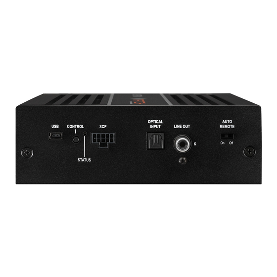
Congratulations on your purchase of this innovative We wish you many hours of enjoyment with your and high-qual ity MATCH product. new MATCH UP 10DSP. Thanks to more than 30 years of experience in research and development of audio products this... - Page 29 This switch allows to activate / deactivate the SCP (Smart Control Port) automatic turn-on feature of the amplifier . Multifunction interface for e.g. an optional remote control or other MATCH UP 10DSP Status LED accessory. The Status LED indicates the operating mode of the amplifier and its DSP memory.
-
Page 30: Initial Start-Up And Functions
/ off additional amplifiers that are con- ware (DCM menu → Signal Management). The nected to the Line Out of the MATCH UP 10DSP. control range of the highlevel inputs is 4 - 16 Volts This is essential to avoid any interfering signals. - Page 31 Optical Input www.audiotec-fischer.com. Please note: It is not possible to connect any USB Optical input in SPDIF format for connecting signal storage devices. sources with a digital audio output. The sampling rate of this input must be between 12 and 96 kHz. Control pushbutton The input signal is automatically adapted to the in- The UP 10DSP provides 10 internal memory lo-...
-
Page 32: Installation
Initial start-up and functions Status LED output until it reaches a safe temperature level The Status LED indicates the operating mode of the again. amplifier and of the DSP memory. green slow flashing: No operating soft- Green: Amplifier is ready for operation. ware installed. - Page 33 Fig. 3: Pin configuration UP 10DSP SPEAKER HIGHLEVEL SYSTEM OUTPUT INPUT CONNECTOR POWER INPUT +12V System Connector Highlevel loudspeaker input rear left (-) / C Highlevel loudspeaker input rear left (+) / C Highlevel loudspeaker input front left (-) / A Highlevel loudspeaker input front left (+) / A Highlevel loudspeaker input front right (-) / B Highlevel loudspeaker input front right (+) / B...
- Page 34 Installation The MATCH UP 10DSP must be installed and ery or an appropriate cable harness from the connected as follows: MATCH accessories program for connection! Caution: Carrying out the following steps will re- 2. Connecting the highlevel speaker inputs E - quire special tools and technical knowledge.
- Page 35 4. Adjustment of the input sensitivity Make sure that the jumper is reinserted properly Attention: It is mandatory to properly adapt and all pins are fully inserted. the input sensitivity of the UP 10DSP to the signal source in order to avoid damage to If you are not sure regarding the signal source the amplifier.
- Page 36 Auto Remote Make sure to disconnect the battery before switch to “Off”. installing the MATCH UP 10DSP! 8. Configuration of the internal DSP Connect the +12 V power cable to the positive The general amplifier settings should be terminal of the battery.
-
Page 37: Jumper Position
ers must not be lower than 4 Ohms for channel 10. Connecting the remote output E - H and 2 Ohms for channel I and J, other- This output (REM OUT) is used to supply re- wise the amplifier protection will be activated. mote signals to additional amplifiers that are Attention: Solely use the connection cable with connected to the Line Out of the UP 10DSP. -
Page 38: Configuration Examples
Configuration examples Example 1: Channel routing with Virtual Channel Processing 4-channel head unit > Front: 3-way fully active; Rear: 2-way fully active + Line Out for external subwoofer Inputs Virtual channels Outputs To speakers From car radio Amp Out A Front L High –... - Page 39 Example 3: 9-channel 1 to 1 channel routing (IOR) e.g. Mercedes Burmester or BMW Harman Kar- don with the optional MATCH UPGRADE harnesses – only in combination with the optional MEC ANALOG IN module From factory Eingänge Ausgänge Zu den Lautsprechern amplifier Front L Full Input A...
- Page 40 Connection to a PC It is possible to freely configure the UP 10DSP with 2. Connect the amplifier to your computer us- our DSP PC-Tool software. ing the USB cable that is included in delivery. The user interface is designed for easy handling If you have to bridge longer distances please use an active USB extension cable with in- of all functions and allows an individual adjustment...
- Page 41 Virtual Channel Processing (VCP) Operating concept of the VCP In opposite to previous methods the Virtual Channel Processing (VCP) is a multi-stage signal processing concept that enables the perfect configuration of complex sound systems, opening up completely new possibilities for sound tuning. The function extends the previous scope of the device by an additional layer of processed channels, which is located between the inputs and outputs.
-
Page 42: Additional Features
Virtual Channel Processing (VCP) – Cross-channel group equalizer Example application: Active multi-way speaker configuration If an input signal (e.g. front left) is first routed to a virtual channel (Front L Full) and this signal is then routed to an active multi-way system (e.g. front left – tweeter, midrange and woofer), the group equalizer of the virtual channel will influence all assigned output channels in their tonality. - Page 43 Configuration of the Virtual Channel Processing (VCP) To configure the VCP, you first have to enable “Virtual Channel Processing” in the DCM menu of the DSP PC-Tool software. Therefore, go to the “Virtual Channel Processing” tab in the DCM menu and click on the right box with the VCP graphic.
- Page 44 Configuration of the Virtual Channel Processing (VCP) Workflow step 2 – Output routing After all the input signals used in the respective signal routing matrix have been configured, the virtual channels must now be assigned to the physical output channels. Here, a virtual signal (e.g. Front L Full) can be assigned to multiple outputs, such as “front left”...
- Page 45 Notes on the configuration of the DSP sound effects (SFX) The MATCH UP 10DSP provides unique DSP sound effects such as Augmented Bass Processing, RealCenter, and more when “Virtual Channel Processing” is enabled. In order to enjoy the DSP sound effects, certain settings must be made in the hardware and software configuration.
- Page 46 Configuration of the Virtual Channel Processing (VCP) 2. Change to the “Virtual to Output Routing” matrix and route the “Virtual E – Front Center Full” channel to the desired output channels (as described in workflow step 2) to which the center processing shall be applied.
- Page 47 Configuration of a subwoofer remote control First, the appropriate remote control must be activated in the “Extended Features” tab in the DCM menu of the DSP PC-Tool software and configured, depending on the model. If the VCP is not activated, the subwoofer remote control of the UP 10DSP is permanently assigned to the output channels I and J.
- Page 48 ACO platform features Beside the unique DSP sound effects the UP 10DSP Remote Output Configuration provides a bunch of new system features. This function controls if the remote output (which In the DCM menu of the DSP PC-Tool software in- switches on and off the connected amplifiers) will dividual settings can be made for several of these be temporarily deactivated during a sound setup...
- Page 49 The phisticated possibilities of diagnosing the connect- MATCH UP 10DSP will reactivate the remote output within a second if a music signal is applied. It is pos- ed speakers. In particular the latest generation of car radios are equipped with additional monitoring sible to either modify the turn-off time of 60 sec.
- Page 50 Installation of a MATCH Extension Card It is possible to extend the functionality of the 6. Make sure that the MEC module is installed MATCH UP 10DSP amplifier by adding further in- properly and all pins are fully inserted into the terfaces like a Bluetooth Audio Streaming module, socket.
-
Page 51: Technical Data
Note: “The Bluetooth word mark and logos are registered trademarks owned by Bluetooth SIG, Inc. and any use of such marks by ® Audiotec Fischer GmbH is under license. Other trademarks and trade names are those of their respective owners.”... - Page 52 Audiotec Fischer GmbH Hünegräben 26 · 57392 Schmallenberg · Germany Tel.: +49 2972 9788 0 · Fax: +49 2972 9788 88 E-mail: match@audiotec-fischer.com · Internet: www.audiotec-fischer.com...
Need help?
Do you have a question about the MATCH UP 10DSP and is the answer not in the manual?
Questions and answers