
Subscribe to Our Youtube Channel
Related Manuals for Audiotec Fischer match M 5.4DSP


Summary of Contents for Audiotec Fischer match M 5.4DSP
- Page 1 M 5.4DSP micro 5-Kanal Miniatur-Verstärker mit 9-Kanal DSP 5-Channel miniature amplifier with 9-channel DSP...
-
Page 2: Herzlichen Glückwunsch
Viel Freude an diesem Produkt wünscht Ihnen das Sie als Kunde direkt von unserer mehr als 30-jäh- Team von rigen Erfahrung in der Forschung und Entwicklung von Audiokomponenten. AUDIOTEC FISCHER Allgemeine Hinweise Allgemeines zum Einbau von MATCH-Kompo- auch in der doppelten Wandverkleidung verbergen nenten können. -
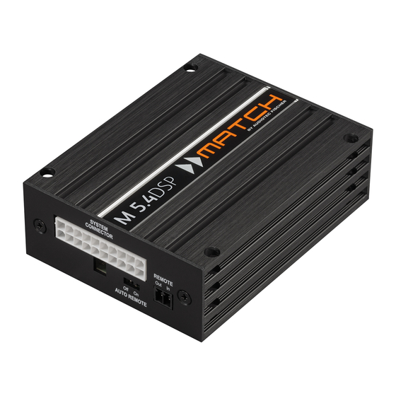
Page 3: Anschluss- Und Bedienelemente
Anschluss- und Bedienelemente System Connector Remote In / Out Anschluss für den MATCH Kabelbaum. Der Remote-Eingang dient zum Einschalten Verwenden Sie ausschließlich ein MATCH der M 5.4DSP. Der Remote-Ausgang dient Original-Anschlusskabel, um den Verstärker zum Einschalten weiterer Verstärker bei Ver- mit dem Autoradio zu verbinden. - Page 4 Inbetriebnahme und Funktionen 1 System Connector 3 Remote In / Out Diese Buchse dient als Signaleingang zum An- Remote In: Der Remote-Eingang dient zum Einschal- schluss des Werksradios, als Signalausgang der ten der M 5.4DSP, sofern die am System Connec- Verstärkerkanäle A - D zum Anschluss der Laut- tor angeschlossene Signalquelle die automatische sprecher sowie als Anschluss an die Bordnetzspan-...
-
Page 5: Status Led
rotes Blinken der Status LED angezeigt. Alternativ Sie diesen Ausgang verwenden, ist es zwingend kann zur Umschaltung die optionale Fernbedienung erforderlich, den Remote-Ausgang (Remote Out) URC.3 verwendet werden. Um zwischen allen in- zum Einschalten des / der an den Line Output F - I ternen Speicherplätzen umschalten zu können, ist angeschlossenen Verstärker zu verwenden, da an- optionales Zubehör, wie z.B. - Page 6 Umschaltung der Leistungsmodi HighPower- / MidPower-Modus Hinweis: Der ausgewählte Betriebsmodus wird auch in den „afpx“-Konfigurationsdateien abge- Die M 5.4DSP verfügt über zwei Leistungsmodi, speichert. Beim Laden einer afpx-Datei kann diese Einstellung über die „Import ACO Features“ Schalt- den „HighPower“-Modus für maximale Performance und den “MidPower”-Modus mit reduzierter Aus- fläche wieder hergestellt werden.
- Page 7 Einbau und Installation Abb. 1: Pinbelegung System Connector SYSTEM CONNECTOR REMOTE AUTO REMOTE Highlevel-Lautsprechereingang hinten links (-) / C Highlevel-Lautsprechereingang hinten links (+) / C Highlevel-Lautsprechereingang vorne links (-) / A Highlevel-Lautsprechereingang vorne links (+) / A Highlevel-Lautsprechereingang vorne rechts (-) / B Highlevel-Lautsprechereingang vorne rechts (+) / B Highlevel-Lautsprechereingang hinten rechts (-) / D Highlevel-Lautsprechereingang hinten rechts (+) / D...
- Page 8 Einbau und Installation Der MATCH M 5.4DSP Verstärker wird wie nach- Die Impedanz pro Kanal darf 4 Ohm nicht folgend beschrieben an das Autoradio ange- unterschreiten, da sonst die Schutzschal- tung des Verstärkers aktiviert wird. schlossen. Achtung: Für die Durchführung der nachfolgenden...
- Page 9 Radio über BTL-Ausgangsstufen verfügt. Schiebereglers die Eingangsempfindlich- keit, bis die Clipping Anzeige erlischt. 5. Konfiguration des Remote-Eingangs Die Einschaltung der MATCH M 5.4DSP erfolgt automatisch bei Ansteuerung über die Hoch- pegel-Lautsprechereingänge oder sobald ein Remote-Signal am Remote-Eingang (Remote 5. Erhöhen Sie die Eingangsempfindlichkeit In) anliegt.
- Page 10 Einbau und Installation 6. Konfiguration des internen DSPs Anschluss eines herkömmlichen passiven Sub- Es wird dringend empfohlen, vor der er- woofers oder Lautsprechers: sten Inbetriebnahme die grundlegenden 1. Trennen Sie die ASIA Steckverbindung des Einstellungen im Verstärker mit Hilfe der Subwooferkabels (C).
- Page 11 Anschluss mit Hilfe eines MATCH Plug & Play Kabels Um die Installation der M 5.4DSP an ein Werks- 4a. Stromversorgung über den Kabelbaum des oder Nachrüstradio deutlich zu vereinfachen, kann Fahrzeugs: der Verstärker auch mit Hilfe von optional erhält- Die Stromversorgung des Verstärkers wird über lichen MATCH Plug &...
- Page 12 Anschluss mit Hilfe eines MATCH Plug & Play Kabels kabels an das Bordnetz muss die Autobat- Hinweis: MOST-Bus terie abgeklemmt werden. Das +12 V Strom- Bei einigen Fahrzeugen kann es notwendig sein, die kabel (gelb, Abb. 5 / min. 4 mm²) ist am Lichtleiterverbindung aus dem Original-Radioan- Pluspol der Batterie anzuschließen.
- Page 13 Abb. 5: Direkte Stromversorgung – Voraussetzung für Betrieb im „HighPower“-Modus Diese Seite des Kabelbaums wird direkt an die Batterie angeschlossen. Dafür werden die dafür vorgesehenen Steckverbinder des Kabelbaums getrennt. Gelbe Leitung: +12 Volt Leitung zum Anschluss an den Pluspol der Autobatterie. Schwarze Leitung: Masse-Leitung zum Anschluss an den Minuspol der Autobatterie oder zum An- schluss an einen Massepunkt des Kfz-Chassis.
- Page 14 Konfigurationsbeispiele Beispiel 1: MidPower-Modus 5-Kanal Anwendung mit fullrange Frontsystem, fullrange Rearsystem und Plug & Play Subwoofer ohne Virtual Channel Processing (VCP) Vorne Passives Frontsystem Plug & Play Kabelbaum vom Autoradio Front L Full Front R Full MATCH Plug & Play Subwoofer wie z.B.
- Page 15 Beispiel 2: HighPower-Modus 5-Kanal Anwendung mit fullrange Frontsystem, fullrange Rearsy- stem und Plug & Play Subwoofer ohne Virtual Channel Processing (VCP) Vorne Passives Frontsystem Front L Full Front R Full MATCH Plug & Play Subwoofer wie z.B. Rear L Full PP 7S-D (Anschluss mit beilie- Rear R Full...
- Page 16 Konfigurationsbeispiele Beispiel 3: HighPower-Modus 7-Kanal Anwendung mit zusätzlichem 2-Kanal Verstärker und Virtual Anwendungsbeispiel mit MATCH M 2.1AMP für BMW und Mercedes Soundsysteme: Fullrange Frontsystem, Vorne Passives Frontsystem Center 4-Kanal Anschluss vom Autoradio Front L Full Front R Full Speaker Output Rear L Full 2 ch Line Output Rear R Full...
- Page 17 Channel Processing: Rearsystem, Center und zwei 4 Ohm Subwoofer BMW Untersitz-Subwoofer MW 8BMW-D Vom Verstärker Mercedes Front-Subwoofer UP W8MB-S4 + 12 V 12 V Batterie Spannungs- versorgung Vom Verstärker Für weitere Anwendungsfälle kontaktieren Sie bitte Ihren MATCH-Fachhändler.
-
Page 18: Anschluss An Den Computer
USB-Kabel an den Computer an. neun DSP Kanäle separat eingestellt werden. Wenn Sie längere Distanzen zu überbrücken Bevor Sie die MATCH M 5.4DSP das erste Mal an haben, verwenden Sie bitte eine aktive USB- Verlängerung mit integriertem Repeater oder einen Computer anschließen, gehen Sie auf unsere... - Page 19 Virtual Channel Processing (VCP) Das Bedienkonzept des VCP Im Gegensatz zu bisherigen Methoden ist das Virtual Channel Processing (VCP) ein mehrstufiges Signalverarbeitungs-Konzept, welches die perfekte Konfiguration komplexer Soundsysteme ermöglicht und somit ganz neue Möglichkeiten des Klangtunings eröffnet. Die Funktion erweitert den bisherigen Umfang des Gerätes um eine neue Ebene an prozessierten Kanälen, welche sich zwischen den Ein- und Ausgängen befindet.
- Page 20 Virtual Channel Processing (VCP) – Kanalübergreifender Gruppen-Equalizer Beispielanwendung: Aktives Mehrwege- System Wird ein Eingangssignal (bspw. Vorne links) erst auf einen virtuellen Kanal geroutet (Front L Full) und dieses Signal anschließend auf ein aktives Mehrwege-System geroutet (bspw. Vorne links – Hochtöner, Mitteltöner und Tieftöner), so ist es möglich, mit Hilfe des Equalizers des virtuellen Kanals alle nachgeschalteten einzelnen Kanäle gleichzeitig in ihrer Tonalität zu beeinflussen.
- Page 21 Konfiguration des Virtual Channel Processing (VCP) Um das VCP zu konfigurieren, muss zuerst das „Virtual Channel Processing“ im DCM-Menü der DSP PC- Tool Software eingeschaltet werden. Gehen Sie dazu in den „Virtual Channel Processing“-Tab und klicken auf die rechte Box mit der VCP-Grafik. Anschließend erfolgt die Konfiguration in drei Schritten – hier am Beispiel einer 3-Wege Konfiguration mit einem 2-Wege Eingangssignal erläutert.
- Page 22 Konfiguration des Virtual Channel Processing (VCP) Workflow-Schritt 2 – Ausgangsrouting Nachdem alle genutzten Eingangssignale in den jeweiligen Signal-Routing-Matrizen konfiguriert wurden, müssen die virtuellen Kanäle nun den physischen Ausgangskanälen zugeordnet werden. Hierbei kann ein virtuelles Signal (bspw. Front L Full) mehreren Ausgängen zugewiesen werden, wie beispielsweise dem vorderen linken Hochtöner, Mitteltöner und Tieftöner.
- Page 23 Kanals gleichzeitig in ihrer Tonalität zu beeinflussen. Konfigurationshinweise für die DSP-Soundeffekte (SFX) Die MATCH M 5.4DSP bietet bei aktiviertem Virtual Channel Processing einzigartige DSP-Sound effekte wie das „Augmented Bass Processing“, den „RealCenter“ und mehr. Um in den Genuss der DSP-Soundeffekte zu kommen, müssen bei der Hard- und Softwarekonfiguration bestimmte Einstellungen vorgenommen werden.
- Page 24 Konfiguration des Virtual Channel Processing (VCP) 2. Wechseln Sie in die „Virtual to Output Routing“ Matrix und routen den Kanal „Virtual E – Front Center Full“ auf den oder die gewünschten Ausgangskanäle (wie im Workflow-Schritt 2 beschrieben), auf wel- che das Center Processing angewendet werden soll. Hinweise zum Eingangsrouting siehe Workflow-Schritt 1 3.
- Page 25 Konfiguration einer Subwoofer-Fernbedienung Konfiguration einer Subwoofer-Fernbedienung Zunächst muss die entsprechende Fernbedienung im Tab „Erweiterte Einstellungen“ im DCM Menü der DSP PC-Tool Software aktiviert und je nach Modell konfiguriert werden. Bei nicht aktiviertem VCP ist die Subwoofer-Fernbedienung bei der M 5.4DSP fest den Ausgangskanälen E und F zugeordnet.
- Page 26 ACO Plattform-Features Neben den einzigartigen DSP-Sound effekten bietet Remote Output Configuration die ACO-Plattform der M 5.4DSP zusätzlich eine An dieser Stelle kann festgelegt werden, ob der Vielzahl an System-Features. Remote-Ausgang, angeschlossenen Im DCM Menü der DSP PC-Tool Software können Endstufen ein- bzw. ausschaltet, während eines für einige dieser System-Features individuelle Sound-Setup-Wechselvorgangs kurzzeitig deakti- Einstellungen vorgenommen werden.
- Page 27 Flashspeichers Platz für 10 Sound Setups anstelle der üblichen zwei. Start-Stopfähigkeit Das Netzteil im MATCH M 5.4DSP stellt die interne Spannungsversorgung auch bei kurzfristigen Ein- brüchen bis hinab zu 6 Volt sicher. Damit ist gewährleistet, dass der MATCH M 5.4DSP...
-
Page 28: Technische Daten
Technische Daten Leistung RMS - Kanal A - D ..............4 x 60 Watt @ 4 Ohm (HighPower) 4 x 35 Watt @ 4 Ohm (MidPower) - Sub Out ................1 x 90 Watt @ 4 Ohm (High- & MidPower) 1 x 160 Watt @ 2 Ohm (High- &... -
Page 29: General Instructions
Congratulations on your purchase of this innovative We wish you many hours of enjoyment with your and high-qual ity MATCH product. new MATCH M 5.4DSP. Thanks to more than 30 years of experience in research and development of audio products this... - Page 30 Use this button to either switch between the SCP (Smart Control Port) setups or initiate a reset of the device. Multifunction interface for e.g. an optional remote control or other MATCH M 5.4DSP Status LED accessory. The Status LED indicates the operating...
-
Page 31: Subwoofer Output
In any case the warran- PC software to configure this amplifier can be ty will be void! downloaded from the Audiotec Fischer website www.audiotec-fischer.com. 2 Auto Remote Please note: It is not possible to connect any USB The M 5.4DSP will be turned on automatically if the... -
Page 32: Initial Start-Up And Functions
Initial start-up and functions 9 Optical Input the M 5.4DSP will not reproduce any audio output until the device is updated via the DSP PC-Tool Optical input in SPDIF format for connecting signal software. sources with a digital audio output. The sampling rate of this input must be between 12 and 96 kHz. -
Page 33: Switching Between The Two Power Modes
Switching between the two power modes HighPower / MidPower mode In the following the most important steps how to ac- tivate the “HighPower” mode are described: The M 5.4DSP has two power modes – the “High- 1. Connect the amplifier to your computer using Power”... -
Page 34: Installation
Installation Fig. 1: Pin configuration of the system connector SYSTEM CONNECTOR REMOTE AUTO REMOTE Highlevel loudspeaker input rear left (-) / C Highlevel loudspeaker input rear left (+) / C Highlevel loudspeaker input front left (-) / A Highlevel loudspeaker input front left (+) / A Highlevel loudspeaker input front right (-) / B Highlevel loudspeaker input front right (+) / B Highlevel loudspeaker input rear right (-) / D... - Page 35 The MATCH M 5.4DSP must be connected to the the MATCH accessories program! head unit (car radio) as follows: 2. Connecting a digital signal source Caution: Carrying out the following steps will re- If you have a signal source with an optical digi- quire special tools and technical knowledge.
- Page 36 Note: If the automatic turn-on function is deac- Make sure to disconnect the battery before tivated it is mandatory to use the remote input installing the MATCH M 5.4DSP! terminal to power up the amplifier! The highlevel Connect the +12 V power cable (yellow) to the signal will be ignored in this case.
- Page 37 7. Connecting a speaker to the subwoofer out- The Subwoofer Output of the M 5.4DSP allows 3. Connect the 2-pole Molex connector of the to connect a passive MATCH Plug & Play sub- woofer (like the MATCH PP 7E-D or PP 7S-D), subwoofer cable to the Subwoofer Output of the a conventional subwoofer or speaker.
- Page 38 Installation with a MATCH Plug & Play cable harness To simplify installation to an OEM or aftermarket fuse rating is lower than 20 A then we strongly radio the M 5.4DSP can also be connected using recommend option 4b. Note: Depending on the vehicle type the con- optional Plug &...
- Page 39 You can now reconnect the car battery. If one the original car radio connector and insert it into of the cable extensions PP-EC 11, PP-EC 25 the car radio connector of the MATCH cable har- ness which has a dedicated recess for this. or PP-EC 40 will be used, the separate power supply has to be connected to the extension cable.
- Page 40 Installation with a MATCH Plug & Play cable harness Fig. 5: Direct power supply – requirement for operating in “HighPower” mode This side of the cable harness will be directly connected to the car´s battery. Therefore you have to separate intended cable joints of the harness. Yellow wire: +12 Volts wire for connecting the M 5.4DSP to the positive terminal of the car´s battery.
- Page 41 Connection to a PC It is possible to freely configure the M 5.4DSP with 3. First turn on the amplifier and then start the our DSP PC-Tool software. software. The operating software will be updat- The user interface is designed for easy handling of ed automatically to the latest version if it is not up-to-date.
-
Page 42: Configuration Examples
Configuration examples Example 1: MidPower mode 5-channel application with fullrange front system, fullrange rear system and plug & play subwoofer without Virtual Channel Processing (VCP) Front Passive system Plug & Play cable harness from car radio Front L Full Front R Full MATCH Plug &... - Page 43 Example 2: HighPower mode 5-channel application with fullrange front system, fullrange rear system and plug & play subwoofer without Virtual Channel Processing (VCP) Front Passive system Front L Full Front R Full MATCH Plug & Play subwoofer like e.g. Rear L Full PP 7S-D (Connection with Rear R Full...
- Page 44 Configuration examples Example 3: HighPower mode 7-channel application with additional 2-channel amplifier and virtual Application example with MATCH M 2.1AMP for BMW and Mercedes sound systems: Fullrange front system, Front Passive system Center 4-channel connec- tion from car radio Front L Full Front R Full Speaker Output Rear L Full...
- Page 45 channel processing: rear system, center and two 4 Ohm subwoofers BMW under-seat subwoofers MW 8BMW-D From amplifier Mercedes front subwoofers UP W8MB-S4 + 12 V 12 V battery power supply From amplifier For further applications please contact your MATCH specialist dealer.
- Page 46 Virtual Channel Processing (VCP) Operating concept of the VCP In opposite to previous methods the Virtual Channel Processing (VCP) is a multi-stage signal processing concept that enables the perfect configuration of complex sound systems, opening up completely new possibilities for sound tuning. The function extends the previous scope of the device by an additional layer of processed channels, which is located between the inputs and outputs.
- Page 47 Virtual Channel Processing (VCP) – Cross-channel group equalizer Example application: Active multi-way speaker configuration If an input signal (e.g. front left) is first routed to a virtual channel (Front L Full) and this signal is then routed to an active multi-way system (e.g. front left – tweeter, midrange and woofer), the group equalizer of the virtual channel will influence all assigned output channels in their tonality.
- Page 48 Configuration of the Virtual Channel Processing (VCP) To configure the VCP, you first have to enable “Virtual Channel Processing” in the DCM menu of the DSP PC-Tool software. Therefore, go to the “Virtual Channel Processing” tab in the DCM menu and click on the right box with the VCP graphic.
- Page 49 Workflow step 2 – Output routing After all the input signals used in the respective signal routing matrix have been configured, the virtual channels must now be assigned to the physical output channels. Here, a virtual signal (e.g. Front L Full) can be assigned to multiple outputs, such as “front left”...
- Page 50 Notes on the configuration of the DSP sound effects (SFX) The MATCH M 5.4DSP provides unique DSP sound effects such as Augmented Bass Processing, RealCenter, and more when “Virtual Channel Processing” is enabled. In order to enjoy the DSP sound effects, certain settings must be made in the hardware and software configuration.
- Page 51 2. Change to the “Virtual to Output Routing” matrix and route the “Virtual E – Front Center Full” channel to the desired output channels (as described in workflow step 2) to which the center processing shall be applied. For information about input routing see workflow step 1 3.
- Page 52 Configuration of a subwoofer remote control First, the appropriate remote control must be activated in the “Extended Features” tab in the DCM menu of the DSP PC-Tool software and configured, depending on the model. If the VCP is not activated, the subwoofer remote control of the M 5.4DSP is permanently assigned to the output channels E and F of the Line Outputs.
- Page 53 ACO platform features Beside the unique DSP sound effects the M 5.4DSP Remote Output Configuration provides a bunch of new system features. This function controls if the remote output (which In the DCM menu of the DSP PC-Tool software in- switches on and off the connected amplifiers) will dividual settings can be made for several of these be temporarily deactivated during a sound setup...
- Page 54 ACO – Advanced 32 Bit CoProcessor car radios is equipped with additional monitoring functions so that failure messages and loss of spe- The MATCH M 5.4DSP amplifier incorporates an extraordinary powerful 32 Bit CoProcessor of the cific features (e.g. fader function) quite often appear latest generation for all monitoring and communi- if a common amplifier will be hooked up –...
-
Page 55: Technical Data
Technical Data Output power RMS - Channels A - D ............4 x 60 Watts @ 4 Ohms (HighPower mode) 4 x 35 Watts @ 4 Ohms (MidPower mode) - Sub Out ..............1 x 90 Watts @ 4 Ohms (High- & MidPower mode) 1 x 160 Watts @ 2 Ohms (High- &... - Page 56 Audiotec Fischer GmbH Hünegräben 26 · 57392 Schmallenberg · Germany Tel.: +49 2972 9788 0 · Fax: +49 2972 9788 88 E-mail: match@audiotec-fischer.com · Internet: www.audiotec-fischer.com...
Need help?
Do you have a question about the match M 5.4DSP and is the answer not in the manual?
Questions and answers