Advertisement
Available languages
Available languages
Table of Contents
- 1 Herzlichen Glückwunsch
- 2 Allgemeine Hinweise
- 3 Anschluss- und Bedienelemente
- 4 Clipping LED
- 5 Anschluss an den Computer
- 6 Technische Daten
- 7 General Instructions
- 8 Usb Input
- 9 Initial Start-Up and Functions
- 10 Installation
- 11 Installation with PP-ISO Cable
- 12 Configuration Examples
- 13 Technical Data
- 14 Warranty Disclaimer
- Download this manual
Advertisement
Table of Contents

Related Manuals for Audiotec Fischer Match UP 7DSP


Summary of Contents for Audiotec Fischer Match UP 7DSP
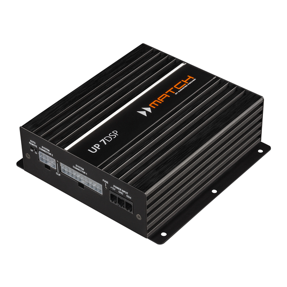
- Page 1 UP 7DSP U P G R A D E 7-Kanal Upgrade-Verstärker mit integriertem 8-Kanal 64 Bit DSP für universelle Anwendungen 7-channel upgrade amplifier with integrated 8-channel 64 Bit DSP for universal applications...
-
Page 2: Herzlichen Glückwunsch
Bereich der Verstärkertechnik. Dabei profitieren Sie als Kunde direkt von unserer mehr als 30-jährigen Team von Erfahrung in der Forschung und Entwicklung von Audiokomponenten. AUDIOTEC FISCHER Allgemeine Hinweise Allgemeines zum Einbau von MATCH-Kompo- den. Achten Sie bitte darauf, dass sich solche Teile nenten auch in der doppelten Wandverkleidung verbergen können. -
Page 3: Anschluss- Und Bedienelemente
Control Input Mono-Vorverstärkerausgang zum Anschluss Multifunktionsanschluss - dient zum An- weiterer Verstärker. Zum Einschalten dieser schluss einer Fernbedienung und weiterem Verstärker muss der Remote-Ausgang ver- MATCH UP 7DSP Zubehör. wendet werden. Optical Input Optischer Eingang im SPDIF-Format für digi- tale Stereosignale. -
Page 4: Clipping Led
Verstärkerkanäle A - D zum Anschluss der Hinweis: Dieser Eingang muss nicht belegt wer- Lautsprecher. Die Impedanz der Lautsprecher darf den, wenn der System Connector 1 benutzt wird. 4 Ohm nicht unterschreiten. Verwenden Sie zur Verbindung der MATCH UP 7DSP mit dem Original-... - Page 5 9 USB Eingang Die „Sampling Rate“ dieses Eingangs muss zwi- Mit Hilfe dieses Eingangs wird die UP 7DSP über schen 12 - 96 kHz liegen. Das Eingangssignal wird das beiliegende Kabel mit dem Computer verbun- automatisch an die interne Abtastrate angepasst. den und kann anschließend über das DSP PC-Tool Um diesen Eingang zu aktivieren und in der Laut- konfiguriert werden.
- Page 6 Inbetriebnahme und Funktionen Der Remote-Ausgang schaltet sich automatisch spannung von 3 Volt RMS. Wenn Sie diesen Aus- gang verwenden, ist es zwingend erforderlich, den während des Power Save Modus sowie bei einem Remote-Ausgang (Remote Out) zum Einschalten Software-Update ab. des / der angeschlossenen Verstärker/s zu ver- Das Audiosignal kann mit Hilfe der DSP PC-Tool wenden, da ansonsten Störgeräusche auftreten Software unabhängig von den anderen Verstärker-...
- Page 7 Einbau und Installation Abb. 1: Pinbelegung System Connector 1 und 2 21 22 23 24 25 26 27 28 11 12 13 14 15 16 17 18 19 20 System Connector 1 Highlevel-Lautsprechereingang hinten links (-) / C Highlevel-Lautsprechereingang hinten links (+) / C Highlevel-Lautsprechereingang vorne links (-) / A Highlevel-Lautsprechereingang vorne links (+) / A Highlevel-Lautsprechereingang vorne rechts (-) / B...
- Page 8 Einbau und Installation Der MATCH UP 7DSP Verstärker wird wie nach- Die Impedanz pro Kanal darf 4 Ohm nicht folgend beschrieben montiert und angeschlos- unterschreiten, da sonst die Schutzschal- sen. tung des Verstärkers aktiviert wird. 2. Anschluss des System Connector 2 Achtung: Für die Durchführung der nachfolgenden...
- Page 9 Wichtig: Das digitale Audiosignal einer Quelle 7. Konfiguration des Remote-Eingangs ist üblicherweise nicht lautstärkegeregelt. Das Die Einschaltung der MATCH UP 7DSP erfolgt bedeutet, dass an sämtlichen Ausgängen der automatisch bei Ansteuerung über die Hoch- UP 7DSP der volle Pegel anliegt. Dies kann im pegel-Lautsprechereingänge des System Con-...
- Page 10 Einbau und Installation stärker mit einem Remote-Signal zu versorgen. Bitte verwenden Sie ausschließlich dieses Signal zur Einschaltung externer Verstärker, um Ein- und Ausschaltgeräusche zu vermeiden. Anschluss mit Hilfe des PP-ISO Kabels Um die Installation der UP 7DSP an ein Werks- oder siehe Abb.
- Page 11 ISO-Kupplung - hier wird der Kabelbaum des Originalradios oder ein ISO-Adapter eingesteckt. ISO-Stecker - diese werden in das Originalradio oder in den ISO-Adapter eingesteckt. Dieser 20-polige Stecker wird in den MATCH UP 7DSP Verstärker eingesteckt. Optional: ISO-Adapter - sollten die ISO-Stecker des PP-ISO Kabelbaums nicht zum Originalradio passen, muss ein ISO-Adapter verwendet werden.
-
Page 12: Anschluss An Den Computer
Anschluss an den Computer MATCH UP 7DSP kann Hilfe Im folgenden Abschnitt lesen Sie die wichtigsten DSP PC-Tool Software frei konfiguriert werden. Die Schritte zum Anschluss und der ersten Inbetrieb- Software stellt alle Funktionen übersichtlich und nahme: bedienerfreundlich zur Verfügung, so dass Sie die- 1. - Page 13 Konfigurationshinweise für die DSP-Soundeffekte Der MATCH UP 7DSP bietet einzigartige DSP- Hinweis: Das Center Processing wird ausschließ- Sound effekte wie das „Augmented Bass Proces- lich auf den Ausgangskanal G angewendet. sing“, den „StageXpander“, den „RealCenter“ und noch mehr. Hinweise für StageXpander- Um jedoch in den Genuss aller DSP-Soundeffekte ClarityXpander-Funktion zu kommen, müssen bei der Hard- und Software-...
- Page 14 Konfigurationsbeispiele 7-Kanal Anwendung mit Center und 2 x 2 Ohm Subwoofer 2-Wege Passivsystem + Koaxialsystem + Center + Subwoofer mit Doppelschwingspule (Dual Voice Coil) Vorne Links Rechts SW 1 SW 2 Links Rechts 2 x 2 Ohm Subwoofer Center Hinten SW = Schwingspule 7-Kanal Anwendung mit 2-Wege Aktivsystem, Center und zwei 1 x 2 Ohm Subwoofern Hochtöner + Tiefmitteltöner + Center + zwei Subwoofer mit einer Schwingspule (Single Voice Coil)
- Page 15 Einbau einer MATCH Extension Card Der MATCH UP 7DSP Verstärker kann durch die 6. Achten Sie auf den richtigen Sitz des MEC Mo- Montage einer MATCH Extension Card (MEC) um duls und darauf, dass alle Kontaktstifte vollstän- weitere Schnittstellen wie beispielsweise einem dig im Sockel stecken.
-
Page 16: Technische Daten
Europäischen Union (EU) zertifiziert. Kaufbeleg erfolgen. Hinweis: „Die Bluetooth Wortmarke und die Logos sind eingetragene Warenzeichen der Bluetooth SIG, Inc. und jegliche Nutzung dieser Marken ® durch die Audiotec Fischer GmbH geschieht unter Lizenz. Andere Handelsmarken und Handelsnamen gehören den jeweiligen Inhabern.“... -
Page 17: General Instructions
Congratulations on your purchase of this innovative We wish you many hours of enjoyment with your and high-qual ity MATCH product. new MATCH UP 7DSP. Thanks to more than 30 years of experience in research and development of audio products this... - Page 18 Line Out. Control Input Line Out Multifunction interface for e.g. an optional Mono line output for connecting external am- remote control or other MATCH UP 7DSP plifiers. Make sure that the remote output is accessory. used to turn on these devices.
-
Page 19: Usb Input
A to D for connecting the loudspeakers. The imped- PC software to configure this amplifier can be ance per channel must not be lower than 4 Ohms. downloaded from the Audiotec Fischer website Solely use this terminal only in combination with the www.audiotec-fischer.com. -
Page 20: Initial Start-Up And Functions
The LED indicates the operating mode of the ampli- ing on / off additional amplifiers that are connected fier and which setup has been chosen. to the Line Out of the MATCH UP 7DSP. This is es- Green: Setup 1 is loaded. - Page 21 “Power Save Mode” via the DSP PC-Tool software. Start-Stop capability The switched power supply of the MATCH UP 7DSP assures a constant internal supply voltage even if the battery’s voltage drops to 6 Volts during engine crank. If the supply voltage drops below 10.5 Volts for more than five seconds the amplifier goes to “Protect mode”...
-
Page 22: Installation
Installation Fig. 1: Pin configuration of the System Connector 1 and 2 21 22 23 24 25 26 27 28 11 12 13 14 15 16 17 18 19 20 System Connector 1 Highlevel loudspeaker input rear left (-) / C Highlevel loudspeaker input rear left (+) / C Highlevel loudspeaker input front left (-) / A Highlevel loudspeaker input front left (+) / A... - Page 23 2. Connecting the System Connector 2 The MATCH UP 7DSP must be installed and con- nected as follows: Two subwoofers and a center speaker can be connected to System Connector 2 by using the Caution: Carrying out the following steps will re- enclosed MATCH connection cable (see fig.
- Page 24 To deactivate the automatic turn-on feature you Make sure to disconnect the battery before have to change the position of the Auto Remote installing the MATCH UP 7DSP! switch to “Off”. Connect the +12 V power cable to the positive 8. Configuration of the internal DSP...
-
Page 25: Installation With Pp-Iso Cable
5. Connect the UP 7DSP amplifier to the power supply of the vehicle as described in item 5 on page 24. Make sure to disconnect the battery before installing the MATCH UP 7DSP! - Page 26 The ISO male connector will either be plugged into the head unit / car radio or into a car-specific adaptor. The 20-pole connector will be plugged into the MATCH UP 7DSP amplifier. Optional: car-specific adaptor – such an adaptor may be required if the ISO connectors of the PP-ISO cable harness does not fit into your head unit / car radio.
- Page 27 Connection to a PC The DSP PC-Tool software enables a free configu- 2. Connect the amplifier to your computer using ration of the UP 7DSP amplifier. the USB cable that is included in delivery. If you The user interface is designed for easy handling of have to bridge longer distances please use an all functions and allows an individual adjustment of active USB extension cable with integrated re-...
- Page 28 Configuration notes for the DSP sound effects The MATCH UP 7DSP offers unique DSP sound Notes for StageXpander and ClarityXpander function effects like “Augmented Bass Processing”, “ StageXpander”, “RealCenter” and many more. In Normally, the settings of the StageXpander and order to enjoy all DSP sound effects, specific set-...
-
Page 29: Configuration Examples
Configuration examples 7-channel application with center speaker and 2 x 2 Ohms subwoofer 2-way passive system + coaxial system + center speaker + subwoofer with dual voice coil Front Left Right VC 1 VC 2 Left Right 2 x 2 Ohms subwoofer Center speaker Rear VC = Voice coil... - Page 30 Installation of a MATCH Extension Card It is possible to extend the functionality of the 6. Make sure that the MEC module is installed MATCH UP 7DSP amplifier by adding further inter- properly and all pins are fully inserted into the faces like a Bluetooth Audio Streaming module, a socket.
-
Page 31: Technical Data
Note: “The Bluetooth word mark and logos are registered trademarks owned by Bluetooth SIG, Inc. and any use of such marks by ® Audiotec Fischer GmbH is under license. Other trademarks and trade names are those of their respective owners.”... - Page 32 Audiotec Fischer GmbH Hünegräben 26 · 57392 Schmallenberg · Germany Tel.: +49 2972 9788 0 · Fax: +49 2972 9788 88 E-mail: match@audiotec-fischer.com · Internet: www.audiotec-fischer.com...
Need help?
Do you have a question about the Match UP 7DSP and is the answer not in the manual?
Questions and answers