Table of Contents
Advertisement
Advertisement
Table of Contents

Subscribe to Our Youtube Channel
Related Manuals for Audiotec Fischer Match M 5DSP


Summary of Contents for Audiotec Fischer Match M 5DSP
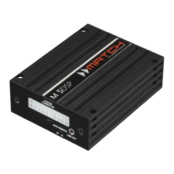
- Page 1 M 5DSP 5-Kanal Verstärker mit integriertem DSP...
-
Page 2: General Instructions
We wish you many hours of enjoyment with your new MATCH M 5DSP. Congratulations on your purchase of this innovative and high-qual ity MATCH product. With the M 5DSP, Audiotec Fischer is setting new Yours, AUDIOTEC FISCHER General instructions General instructions for connecting the M 5DSP... - Page 3 Use this button to either switch between the Control Input setups or initiate a reset of the device. Multifunction interface for e.g. an optional remote control or other MATCH M 5DSP ac- Remote In / Out cessory. The remote input can be used to switch on the M 5DSP.
-
Page 4: Initial Start-Up And Functions
Initial start-up and functions 1 System Connector ly to a 12 Volt source. Refer to connection instruc- Please use this terminal only in combination with tions in section 4, page 21. the cable harness that is included in delivery or an 5 USB Input appropriate cable from the MATCH accessories program. -
Page 5: Optical Input
Status LED. Notice: Attention: After erasing the setups from memory signals and no Dolby-coded digital audio stream. the MATCH M 5DSP will not reproduce any audio Control Input output until a new setup is loaded. This multi-functional connector is designed for... -
Page 6: Switching Between The Two Power Modes
Switching between the two power modes HighPower / MidPower mode In the following the most important steps how to ac- tivate the “HighPower” mode are described: The M 5DSP has two power modes - the “HighPow- er” mode for maximum perfomance and “MidPower” the USB cable that is included in delivery. -
Page 7: Installation
Installation Fig. 1: SYSTEM CONNECTOR AUTO REMOTE LINE OUT Highlevel loudspeaker input rear left (-) Highlevel loudspeaker input rear left (+) Highlevel loudspeaker input front left (-) Highlevel loudspeaker input front left (+) Highlevel loudspeaker input front right (-) Highlevel loudspeaker input front right (+) Highlevel loudspeaker input rear right (-) Highlevel loudspeaker input rear right (+) Loudspeaker output rear right (-) - Page 8 The MATCH M 5DSP must be connected to the head unit (car radio) as follows: automatically activates the digital input if a dig- ital audio signal is detected. This function can Caution: Carrying out the following steps will re- be deactivated via the DSP PC-Tool software.
- Page 9 Installation on the vehicle chassis, i.e. an area which has 2. Next, connect the 2-pole Molex connector of the subwoofer cable to the Subwoofer Output been cleaned of all paint residues. 5. Connecting the remote input The remote input (Remote In) has to be con- nected to the remote output of the signal source if the signal source which is connected to the highlevel inputs is not activating the “automatic...
-
Page 10: Installation With Pp-Iso Cable
Installation with PP-ISO cable To simplify installation to an OEM or aftermar- we strongly recommend option 4b. ket radio the M 5DSP can also be connected us- Note: Depending on the vehicle type the con- ing the optional PP-ISO cable (2.2 m version, nections for switched (ACC+) positive terminal and constant positive terminal can be inter- art. - Page 11 Installation with PP-ISO cable of the cable extensions PP-EC 11, PP-EC 25 the original car radio connector and insert it into or PP-EC 40 will be used, the separate power the car radio connector of the MATCH cable har- ness which has a dedicated recess for this. supply has to be connected to the extension cable.
- Page 12 Fig. 4: Direct power supply - requirement for operating in “HighPower” mode This side of the cable harness will be directly connected to the car´s battery. Therefore you have to separate intended cable joints of the harness. Yellow wire: +12 Volts wire for connecting the M 5DSP to the positive terminal of the car´s battery. Black wire: ground wire for connecting the M 5DSP to the negative terminal of the battery or directly to the car´s chassis.
-
Page 13: Unique Features Of The M 5Dsp
Unique Features of the M 5DSP Smart highlevel input Power Save Mode The latest generation of OE car radios incorpo- The “Power Save Mode” is incorporated in the ba- rates sophisticated possibilities of diagnosing the sic setup of the DSP PC-Tool software. It allows features (e.g. -
Page 14: Technical Data
Technical Data Output power RMS / max: • Front/Rear channels @ 4 Ohms in “HighPower” mode ..... 4 x 60 / 120 Watts • Front/Rear channels @ 4 Ohms in “MidPower” mode ....4 x 35 / 70 Watts • Subwoofer output @ 4 Ohms ............. 1 x 90 / 180 Watts •... - Page 15 Audiotec Fischer GmbH Hünegräben 26 · 57392 Schmallenberg · Germany Tel.: +49 2972 9788 0 · Fax: +49 2972 9788 88...
Need help?
Do you have a question about the Match M 5DSP and is the answer not in the manual?
Questions and answers