Table of Contents
Advertisement
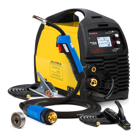
MANUAL inverter
semi-automatic WELDING
Model:
MIG 208 Alu Synergy
Drawings devices in the manual may differ from the original colors.
Translation of the original instructions.
with
NOTE: Please use a welder after a very careful reading the manual.
1. In order to ensure safety should be determined by qualified personnel responsible for installation,
maintenance, periodic inspection and repair equipment.
2. In order to ensure safety before working with the machine carefully and with full understanding
refer to the following instructions.
3. After reading the following instructions and keep it in a place accessible to other users of the
device.
1
Advertisement
Table of Contents

Related Manuals for Magnum MIG 208 Alu Synergy


Summary of Contents for Magnum MIG 208 Alu Synergy
- Page 1 MANUAL inverter semi-automatic WELDING Model: MIG 208 Alu Synergy Drawings devices in the manual may differ from the original colors. Translation of the original instructions. with NOTE: Please use a welder after a very careful reading the manual. 1. In order to ensure safety should be determined by qualified personnel responsible for installation, maintenance, periodic inspection and repair equipment.
-
Page 3: Table Of Contents
Table of Contents INTENDED USE ..........INTENDED USE ..........INTENDED USE ..........INTENDED USE ..................................................................... 2. TECHNICAL DATA 2. TECHNICAL DATA 2. TECHNICAL DATA 2. TECHNICAL DATA PRECAUTIONS FOR USE ......... PRECAUTIONS FOR USE ......... PRECAUTIONS FOR USE ......... -
Page 4: Intended Use
MIG 208 Alu Synergy is intended for all kinds of welding workshop locksmith, repair shops, automotive industry, factories, etc. The device is dedicated to professionals requiring the highest standards, for welding equipment. -
Page 5: Technical Data
TECHNICAL DATA MODEL MIG 208 Alu Synergy Power AC 230 [V], 50/60 [Hz] required safety 20 [A] Current MIG / MAG 20 to 180 [A] Power MIG / MAG 15 to 23 [V] Load voltage 78 [V] Wire diameter * (* see 0.6 / 0.8 / 0.9 / 1.0 / 1.2 [mm]... - Page 6 SAFETY INSTRUCTION electric welding 3.1. General thoughts. a) The work must begin rested, sober, dressed in clothing made of slow-burning fabric or leather, her hair covered with a beret or cap, on the legs have shoes with trousers hardly inflammatory hands welding gloves and personal protection apron leather, welding mask, goggles, personal respiratory protective equipment.
- Page 7 When welding on scaffolding check the status of their efficiency. and) Protect respiratory system, eyes, face and hands from burns and exposure through the use of appropriate personal protection. k) Switch individual air extraction, when this is established, the gaseous effluents are removed from the position. Use only proper, undamaged and not oiled tools and support workshop.
- Page 8 ELECTRIC SHOCK CAN KILL: Welding apparatus produce a high voltage. Do not touch the torch or welding material ELECTRIC SHOCK CAN KILL: Welding apparatus produce a high voltage. Do not touch the torch or welding material connected when the device is turned on to the network. All the elements forming the welding current circuit can cause electrical shock and should therefore be avoided touching them with bare hands or by wet or damaged protective clothing.
-
Page 9: Symbols
SYMBOLS To reduce the possibility of injury, the user must first read all the instructions. General warning sign notes for each user on the general danger. It is combined with other instructions warning or other symbols that failure can lead to personal injury or equipment damage. -
Page 10: Construction And Control Panel
CONSTRUCTION AND CONTROL PANEL Method 3 sec. mig mig son-man-tig-mma MIG 208 Alu synergy Choice 3 sec. Gaseous MaterialScience about point-2t / 4t 1. Control Panel. 2. The seat current, the output "minus". 3. Euro-slot. 4. Jack current, output "plus". 5. - Page 11 Pressing the knob for 2 seconds or more and release to enter the menu where you can choose the method of welding. The selection is made by turning the knob in either direction. The selected symbol will then blink. The choice must be confirmed by briefly pressing the knob.
-
Page 12: Synergistic Programs And Settings
If spot welding is off, briefly press the knob lower. The symbol will flash together with the chosen option 2t and 4t. The selection is done by turning the knob lower. Approval followed by another short pressing the lower knob. If the welder is turned on while working 4t display shows the both in manual mode and symbol... - Page 13 Upon rotation of the knob to the right or left of the display will change the numerical value of wire feed speed, thickness of the material in millimeters, and graphical thickening or thinning of the material: Depending on the thickness of the material will also appear ATC symbol. ATC is an advanced thermal control function, activated when welding thin materials to a thickness of 1.5 mm.
-
Page 14: Advanced Settings
5.2 Advanced Settings. MIG 208 Alu Synergy have the opportunity to adjust additional parameters for advanced MIG-MAG, both in synergy mode and manual. Starting wire speed (Access). Adjusting the range of 30 to 100 [%] the speed of the tray. -
Page 15: Kit Contents
KIT CONTENTS The following items should be included: welding machine x 1 pc. Work cable MIG / MAG x 1 pc. Work cable MMA x 1 pc. Cable to the common terminal x 1 pc. Feed roller kit. Attention! For the safety of children should not be left freely accessible parts of the packaging (plastic bags, cardboard, polystyrene, etc.). -
Page 16: Fitting Wire Welding - Mig / Mag
7.2 Fitting wire welding - MIG / MAG welding. ATTENTION! Before all work carried out on the unit, unplug the power cord. 1. Make sure that the device is not connected to the mains. 1. Make sure that the device is not connected to the mains. 2. -
Page 17: Connection Of Protective Gas
7. Push wire in the groove by tightening the drive rollers 7. Push wire in the groove by tightening the drive rollers pressure. 8. Remove gas nozzle and contact tip, unscrew. 8. Remove gas nozzle and contact tip, unscrew. 9. Switch on the device. 9. -
Page 18: Practical Recommendations Mig / Mag Welding
7.6 Practical recommendations MIG / MAG welding. Butt welds in the flat position must be carried out using "push" for thin components and technology "pull" for items thicker. Butt welds in vertical position for thin elements should be done from top to bottom. Fillet welds in position nabocznej should be carried out using "push", but with an additional tilt the torch in a plane perpendicular to the direction of welding. - Page 19 GRUBOKROPLOWY - used for MIG / MAG low current densities and long arc not recommended in forced positions SPRAY used in the MAG gas mixtures not recommended in forced positions Short circuit used in MAG welding with short arc recommended for welding parts of small thickness and forced positions The protective gas guards determine the efficiency of the welding area, but also of a process for transferring the metal in the arc, the welding speed and the shape of the weld.
-
Page 20: Cleaning And Maintenance
90% He + 7.5% Ar + weakly oxidising Corrosion resistant, short-arc welding 2.5% CO 2.5% CO Low alloyed steels, high-impact, short-arc welding 60% He + 35% Ar + 5% oxidising WHAT WHAT CLEANING AND MAINTENANCE Degree of protection of this device is IP21S, so, do not use the unit in the rain, or expose it to moisture. -
Page 21: Interference Welders At Work (Codes Device Errors)
Every month? ABOUT Check the condition of the electrical connections inside the source. ABOUT Check the condition of the electrical connections inside the source. ABOUT Oxidized surfaces should be clean and tighten loose parts. ABOUT Oxidized surfaces should be clean and tighten loose parts. ABOUT Clean the inside of the device by means of compressed air. -
Page 22: Storage And Transport
STORAGE AND TRANSPORT It is recommended to keep the cleared device in its original packaging. Always store the device in a dry, ventilated place out of reach of children and unauthorized persons. Protect the device from vibrations and shocks during transport. UTILIZATION The packaging materials for use as a secondary raw material. -
Page 23: Declaration Of Conformity
DECLARATION OF CONFORMITY The product complies with European Union with The product meets the standards: LVD 2014/35 / EU EMC 2014/30 / EU RoHS 2011/65 / EU The product meets the requirements of harmonized standards: EN 60974-1: 2012 EN 60974-10: 2014 WARRANTY. - Page 24 WWW.SPAWSC.PL WWW.MAGNUM-WELDING.COM Cracow. 2017 KR. v1...
Need help?
Do you have a question about the MIG 208 Alu Synergy and is the answer not in the manual?
Questions and answers