Table of Contents
Advertisement
Our Customer Service staff are ready to provide assistance.
If a part is damaged or missing, replacement parts can be
shipped from our facility.
For help with assembly, or for additional product
information, call our North American toll-free number:
1-800-567-8979
You will need this manual for safety instructions, operating procedures, and warranty.
Put it and the original sales invoice in a safe, dry place for future reference.
Vous aurez besoin de ce guide pour les instructions de sécurité, les procédures d'utilisation et la garantie.
AC/DC Pulse TIG/ARC Welder
QUESTIONS? 1-800-567-8979
SAVE THIS MANUAL
CONSERVEZ CE GUIDE
Conservez-le dans un endroit sûr et sec pour référence future.
Model:
Notre personnel de service à la clientèle sera prêt à
fournir assistance. Si une pièce est endommagée ou
manquante, des remplacements seront expédiés de notre
usine.
Pour de l'aide avec l'assemblage, ou pour des
informations additionnelles sur le produit, appeller notre
numéro sans frais nord-américain : 1-800-567-8979
WAVE 200KD
WE3107 v.110413
Advertisement
Table of Contents

Related Manuals for Magnum WAVE 200KD


Summary of Contents for Magnum WAVE 200KD
- Page 1 WAVE 200KD Model: AC/DC Pulse TIG/ARC Welder QUESTIONS? 1-800-567-8979 Our Customer Service staff are ready to provide assistance. Notre personnel de service à la clientèle sera prêt à If a part is damaged or missing, replacement parts can be fournir assistance. Si une pièce est endommagée ou shipped from our facility.
- Page 2 CATALOGUE GENERAL SAFETY RULES TECHNICAL SPECIFICATION KNOW YOUR WELDER INSTALLATION OPERATION TROUBLESHOOTING DIAGRAM & PARTS LIST WARRANTY...
-
Page 3: General Safety Rules
WARNING: Read and understand all instructions. Failure to follow all instructions listed below may result in serious injury. CAUTION: Do not allow persons to operate or assemble this WAVE 200KD until they have read this manual and have developed a thorough understanding of how the WAVE 200KD works. - Page 4 -Do not drape cables over or around your body. -Wear a full coverage helmet with appropriate shade (see ANSI Z87.1 safety standard) and safety glasses while welding. -Wear proper gloves and protective clothing to prevent your skin from being exposed to hot metals, UV and IR rays.
- Page 5 shade 10 lens; for above 160 Amps, use a shade 12. Refer to the ANSI standard Z87.1 for more information. -Cover all bare skin areas exposed to the arc with protective clothing and shoes. Flame-retardant cloth or leather shirts, coats, pants or coveralls are available for protection. -Use screens or other barriers to protect other people from the arc rays emitted from your welding.
- Page 6 WAVE 200KD operation. Replace or repair damaged or worn parts immediately. • Store idle WAVE 200KD. When WAVE 200KD is not in use, store it in a secure place out of the reach of children. Inspect it for good working condition prior to storage and before re-use.
- Page 7 TECHNICAL SPECIFICATION TERM UNIT WAVE 200KD Rated Input Voltage Power Frequency 50/60 Rated Input Capacity Rated Input Current Output No Load Voltage Rated Working Voltage DC Argon Welding Current 5~ 200 AC Argon Welding Current 10~ 200 Stick Welding Current 5~...
-
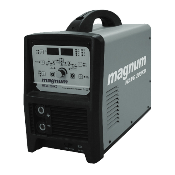
Page 8: Front Panel
Welding regulations parameter table (only for reference) Top Dia WORK Wire Argon Tungste Welding Φ Material Designe Thicknes Flow n Stick Mode Current Polarity Angle (mm) Type d Joint Φ Dia Φ (mm) (mm) (mm) Vertical 1.6~3.0 50~90 12~20° 0.12~0.25 Joint 1.6~2.5 8~12... - Page 9 1.3. AC/DC transfer knob Use this knob to choose the AC or DC, when AC indicator light, means the machine is under AC mode. When DC indicator light, means the machine is under DC mode. 1.4. Pulse switch Use this knob to choose whether you need the pulse, when the indicator light, means it is under pulse mode.
- Page 10 When the input voltage is below or over the specified voltage, the machine will cut off the power to protect itself until the input voltage is available. INSTALLATION 1. POWER REQUIREMENT - AC single phase 220V, 60 HZ with a 50 amp circuit breaker is required. DO NOT OPERATE THIS UNIT if the ACTUAL power source voltage is less than 220 volts AC or greater than 240 volts AC.
- Page 11 5. Input connection method Input power Remote control box Gas cylinder EXPOSURE TO A WELDING ARC IS EXTREMELY HARMFUL TO THE EYES AND SKIN! Prolonged exposure to the welding arc can cause blindness and burns. Never strike an arc or begin welding until you are adequately protected.
- Page 12 Step3: Use this adjustment to adjust the parameter selected on Step2 Step2: Press this knob to choose the parameter Step1: Press this knob, choose MMA, the current display shows the pre-set current,voltage display shows the open circuit voltage. 2. TIG: Step3:...
- Page 13 2.2 DC pulse TIG welding Set 【Welding mode knob】 to “TIG ”, 【AC/DC transfer knob】 to “DC ” , 【Pulse switch】 set on “Pulse” would enter into the by “Parameter knob””Parameter positive knob”: 】 to adjust the Pre-flow time; 【 】...
- Page 14 2.3.2 4T Latch Mode This mode of welding is mainly used for long welding runs to reduce operator fatigue. In this mode the operator can press and release the torch trigger and the output will remain active. To deactivate the power source, the trigger switch must again be depressed and realized, thus eliminating the need for the operator to hold the torch trigger.
- Page 15 2.5 AC pulse TIG welding Set 【Welding mode knob】to “TIG ” and 【AC/DC transfer knob】to “AC ”, 【Pulse switch】set on “Pulse” would enter into AC pulse TIG welding mode. Then to choose by “Parameter knob””Parameter positive knob”: 】 to adjust the Pre-flow time; 【...
- Page 16 Based on different welding position, there are different welding joint, see following images for more information. 3.3 GROUND CLAMP CONNECTION Clear any dirt, rust, scale, oil or paint on the ground clamp. Make certain you have a good solid ground connection.
- Page 17 3.5 SELECTING THE PROPER ELECTRODE There is no golden rule that determine the exact rod or heat setting required for every situation. The type and thickness of metal and the position of the work piece determine the electrode type and the amount of heat needed in the welding process.
- Page 18 3.7.1 Holding the electrode The best way to grip the electrode holder is the way that feels most comfortable to you. Position the Electrode to the work piece when striking the initial arc it may be necessary to hold the electrode perpendicular to the work piece.
- Page 19 Stringer Bead Weave Bead The weave bead Used when you want to deposit metal over a wider space than would be possible with a stringer bead. It is made by weaving from side to side while moving with the electrode. It is best to hesitate momentarily at each side before weaving back the other way.
- Page 20 3.7.6 Finish the bead As the coating on the outside of the electrode burns off, it forms an envelope of protective gases around the weld. This prevents air from reaching the molten metal and creating an undesirable chemical reaction. The burning coating, however, forms slag. The slag formation appears as an accumulation of dirty metal scale on the finished weld.
- Page 21 Tungsten Electrode Current Ranges Guide for Selecting Filler Wire Diameter Tungsten Electrode Types Aluminium Welding Material...
- Page 22 Welding Rate TIG Welding is generally regarded as a spec ialised proc ess that requires operator competency. While many of the principles outlined in the previous Arc Welding section are applicable a comprehensive outline of the TIG Welding proc ess is outside the scope of this Operating Manual.
- Page 23 Thermal relay broken Replace the thermal relay Over/Lack voltage more Become normal after voltage ok Than 15% Relevant Replace the potentiometer potentiometer Panel knob broken not adjustable Main PC board broken Replace the PC board Find the disconnected wire and Cable broken/fallen off Connect reliably Digital...
- Page 24 DIAGRAM & PARTS LIST Code number Description 2.05.08.115 Handle 1.1.01.01.0742 Enclosure 1.1.10.34.0030 Remote control absorption module 1.1.05.11.0062 Secondary inverter arc plate 2.05.17.028 Tension disc 2.04.30.103 Cable holder 1.1.11.34.0046 Power line 2.07.80.987 Switch 2.07.54.115 Aerial socket 1.1.01.03.1740 Back panel 2.02.02.034 Connecting screw rod 2.06.14.813 Copper nut...
- Page 25 1.1.10.34.0029 1.1.05.01.0547 Switching power supply board 1.1.05.10.0038 Pulse run-on plate 2.07.37.553 Single phase rectifier bridge 1.1.05.11.0064 Rectifier inverter board 2.07.33.996 Single tube (IGBT) 2.05.05.173 Radiator support 2.07.43.962 Rectifier heat sink 1.1.01.04.1411 Bottom panel 2.05.05.999 Feet 1.1.01.05.3106 Mounting plate 2.07.25.107 Output reactor 1.1.04.05.0049 Coupling transformer 2.07.55.203...
Need help?
Do you have a question about the WAVE 200KD and is the answer not in the manual?
Questions and answers