Table of Contents
Advertisement
Quick Links
INVERTER OPERATING MANUAL
SEMI-AUTOMATIC WELDING
Model:
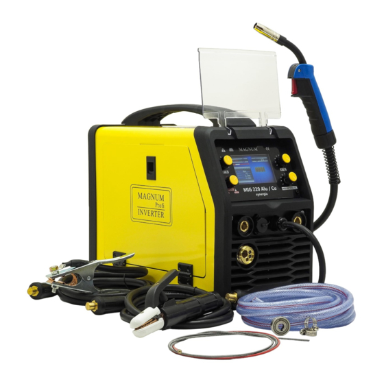
MIG 220 Alu / Cu synergy
The drawings of the device in the manual may differ in colors from the original.
Original instruction.
With
ATTENTION: Please use the welding machine after reading the operating manual very carefully.
1. To ensure safe operation, select qualified personnel responsible for the
installation, maintenance, periodic inspection, and repair of this equipment.
2. In order to ensure safety, before working with the device, carefully and fully
understand the following operating instructions.
3. After reading the following instruction manual, place it in a place accessible to
other users of the device.
1
Advertisement
Table of Contents

Subscribe to Our Youtube Channel
Related Manuals for Magnum MIG 220 Alu synergy


Summary of Contents for Magnum MIG 220 Alu synergy
- Page 1 INVERTER OPERATING MANUAL SEMI-AUTOMATIC WELDING Model: MIG 220 Alu / Cu synergy The drawings of the device in the manual may differ in colors from the original. Original instruction. With ATTENTION: Please use the welding machine after reading the operating manual very carefully. 1.
-
Page 3: Table Of Contents
Table of Contents INTENDED USE ..............4 CONTENTS OF THE SET ..................4 TECHNICAL DATA....................5 RULES FOR SAFE USE .............. 6 EXPLANATION OF SYMBOLS ..................9 CONSTRUCTION AND CONTROL PANEL ................ 10 6.1 Device menu....................11 6.2 Synergic programs - MIG SYN .......... -
Page 4: Intended Use
1. INTENDED USE Device MIG_220_Alu _ / _ Cu_synergy MAGNUM brand is a professional, synergistic semi-automatic welding machine, designed for manual, electric welding of low-carbon steel, low-alloy steel (MAG), alloy steel (MIG) and aluminum and its alloys. The device can also be Brazed, MMA and TIG Lift welding. It is intended for all types of welding work, in locksmith workshops, repair and industrial workshops, factories, etc. -
Page 5: Technical Data
3. TECHNICAL DATA MODEL MIG 220 Alu / Cu synergy Power AC 230 [V], 50 [Hz] 6.4 [kVA] Power consumption max. Required protection. 20 [A] Welding current MIG / MAG 40 ÷ 200 [A] 10 ÷ 200 [A] Welding current TIG Lift 10 ÷... -
Page 6: Rules For Safe Use
4. RULES OF SAFE USE Read all and all safety regulations instructions.Failure to follow the health and safety regulations and instructions may result in electric shock, fire and / or serious injury. Save all safety regulations and instructions for future reference. Keep children away from the working area of the device. - Page 7 d) prepare adequate face and eye protection, e) check the condition of the connections of the welding installation and the working handle, f) check that the welding process does not pose a threat to the environment (arc radiation, possibility of ignition of easily ignitable elements), g) check if there is no ignition on the other side when welding on the wall, 3.3.
- Page 8 d) Organize the welding equipment. 3.6. Final remarks. a) When welding works inside tanks, boilers or other closed rooms (up to 15 m3), the welder should be insured by another person outside. ELECTRIC SHOCK CAN KILL: Welding equipment produces high voltage. Do not touch the welding gun or connected welding material when the device is plugged in.
-
Page 9: Explanation Of Symbols
5. EXPLANATION OF SYMBOLS To reduce the possibility of injury, the user must read the entire manual first. A general warning sign draws the attention of each user to general dangers. It is used in conjunction with other cautionary notes or symbols that, if ignored, could result in personal injury or equipment damage. -
Page 10: Construction And Control Panel
6. CONSTRUCTION AND CONTROL PANEL 1. Control panel. 2. Euro-socket for connecting the MIG-MAG work cable. 3. "PLUS" current output socket. 4. Cable with a plug to select the polarity - for MIG-MAG welding, it must be plugged into one of the sockets, according to the selected polarity. -
Page 11: Device Menu
7. Knob for adjusting the wire feed speed for the MIG-MAG method. Adjustment of the welding current value for the MMA and TIG Lift methods. 8. Welding voltage value control knob for the MIG-MAG method. For MMA method - adjustment of the Arc force function. 9. -
Page 12: Synergic Programs - Mig Syn
Turn the knob 10 to select the desired welding method. Confirm the selection by pressing the knob 10. Looking from the left, you can choose from: MIG SYN - MIG-MAG welding with the use of synergic programs. MIG MAN - MIG-MAG welding with manual settings. MMA - MMA welding. - Page 13 Another pressing of the MENU knob (10), depending on the previously selected welding method, is either a screen with the shielding gas selection (program FE) or the wire diameter selection screen. The next screen is a choice of 2T or 4T. Pressing the MENU knob (10) again will bring you to the next screen - selection of the thickness of the welded material.
- Page 14 Information about the selected welding method. Detailed Summary Field: WELDWAY: welding method. MODE: 2T or 4T. GAS: CO2 or MIX. The device does not display the word Argon. In any case, it replaces them with the word MIX. MATERIAL: type of material to be welded. DIAMETER: selected wire diameter.
- Page 15 will set the optimal wire feed speed. The device allows you to correct this speed and change it in full range, even if it is set incorrectly. The correct numerical value for the wire feed speed is displayed in white. The graphic slider will also be in the white area.
-
Page 16: Mig-Mag Manual Settings
6.3 Manual MIG-MAG settings When selecting the MIG-MAG method with manual settings (MIG MAN) the device does not impose or enforce any settings (except for selecting 2T or 4T). The user can set the wire feed speed, voltage and inductance in the full and any range. -
Page 17: Mma Settings
The Spool gun holder is an optional welding holder (sold separately), characterized by a considerable length - usually 5 to 10 meters - and a wire spool feeder with a diameter of 100 mm, mounted on the handle. To weld with such a holder: - connect the ground cable to the material to be welded, - coil or remove the welding wire from the device feeder chamber, - set the switch on the device to the Spool Gun position,... -
Page 18: Tig Lift Settings
Although the device offers a choice of only the most commonly used electrode diameters (from 2.5 mm to 4.0 mm), later you can use smaller diameters (e.g. 1.6 mm, 2.0 mm), because the device does not limit the welding current adjustment range. After selecting the electrode diameter, the thickness of the welded material should be set: When all the above parameters have been set, the device "shakes"... -
Page 19: Use
7. USE 7.1 Connecting to the network mains equipment must be checked for size Before attaching this voltage, number of phases and frequency. The parameters of the supply voltage are given in the technical data section of this manual and on the rating plate of the device. -
Page 20: Loading The Electrode Wire
we usually connect to the "-" socket, in the case of using the self-shielding wire to the "+" socket (contrary to the hint displayed on the screen of the device). The second, empty output socket is plugged into the plug hanging on the built-in cable. This is necessary to close the welding current circuit. -
Page 21: Connecting The Shielding Gas
7. Press the wire into the grooves of the drive rolls by tightening the clamp. 8. Remove the gas nozzle and unscrew the contact tip. 9. Turn on the device. 10. Unroll the handle so that it is in a straight line, then press the button on the handle or start the test wire feed until the wire appears in the outlet (approx. -
Page 22: Practical Recommendations For Mig / Mag Welding
7.6 Practical recommendations for MIG / MAG welding. Butt welds in the flat position should be made using the "push" technique for thin elements and the "pull" technique for thicker elements. Butt welds in the vertical position for thin elements should be made from top to bottom. -
Page 23: Mma Welding
7.8 TIG LIFT welding In order to use MIG 220 Alu / Cu synergy for TIG LIFT welding, you need to obtain optional accessories such as a tig torch with a gas valve in the handle - MAGNUM SR26V or SR17V. -
Page 24: Cleaning And Maintenance
The arc is struck by rubbing the welded material with a non-consumable electrode. Lightly touch the workpiece electrode (1) and detach the electrode from the workpiece by tilting the handle in such a way that the gas nozzle touches the workpiece (2 and 3), which will ignite the arc. -
Page 25: Interference Welding Machine
Every day: Clean the mass handle and the gas nozzle from splinters, lubricate with anti- spatter agents. Check that the cables are securely connected. Check the condition of the wires. Replace damaged cables. Make sure that there is free air flow around the device. ... -
Page 26: Storage And Transport
10. STORAGE AND TRANSPORT It is recommended to store the cleaned device in its original packaging. Always store the devices in a dry, ventilated place, inaccessible to children and bystanders. Protect the device against vibrations and shocks during transport. 11. DISPOSAL The packaging materials can be used as a secondary raw material. -
Page 27: Declaration Of Conformity
Importer / producer: Spaw 30-731 Krakow ul. Mowers 3 13. DECLARATION OF CONFORMITY With The product complies with the standards of the European Union... - Page 28 WWW.MAGNUM-WELDING.COM KR.20.v1...
Need help?
Do you have a question about the MIG 220 Alu synergy and is the answer not in the manual?
Questions and answers