Table of Contents
Advertisement
TECHNICAL SPECIFICATIONS - MAGNUM
MODEL
WELDING PROCESS
WIRE ALLOYS
WIRE SIZES (DIAMETERS)
SPOOL SIZE
RATED WELDING CURRENT
AND DUTY CYCLE
OVERALL WEIGHT
CABLE LENGTH
OVERALL SIZE (BOUNDING BOX)
METHOD OF GUIDANCE
METHOD OF COOLING
UNPACKING THE SPOOL GUN
The spool gun is factory-assembled and tested, and then packed in its own cush-
ioned carrying case. It is shipped fully-equipped to weld with 0.035 inch diameter alu-
minum wire. After opening the case, check that it contains the following items:
1. One fully assembled K2532-1 spool gun.
2. One T11862-65 Conical Compression Spring for use with alloy 5356 wire (spool
not included).
3. One spool of 0.035 aluminum alloy 4043 wire
4. Three S19726-3 contact tips
5. One instruction manual (IM913)
6. One M21182 electrical harness with toggle switch.
1
INSTALLATION
K2532-1 Magnum
Aluminum GMAW (MIG), DC electrode positive
polarity with 100% argon welding shielding gas.
Aluminum only: alloys 4043 or 5356
Solid wire 0.030 or 0.035 inches (0.8 or 0.9 mm)
1 lb. weight, nominal 4 inch diameter spool
130 amps at 30% for 10-minute basis
3.5 lbs. with cable but without case or spool
10.0±0.2 feet
In inches: 15.75 long x 10.50 high x 4.25 thick max.,
without case or gun cable.
Semiautomatic (manually-guided)
Air-cooled
3
2
Plastic Bag
A-1
®
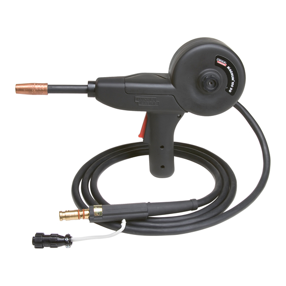
100SG SPOOL GUN K2532-1
®
100SG Spool Gun
5
4
6
Advertisement
Table of Contents


Need help?
Do you have a question about the 100SG SPOOL GUN and is the answer not in the manual?
Questions and answers