Table of Contents
Advertisement
Quick Links
Advertisement
Table of Contents

Related Manuals for Beltone Mira Series


Summary of Contents for Beltone Mira Series
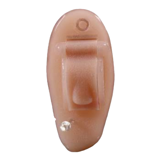
- Page 1 Technical Manual Mira Invisa CIC Beltone Mira M15 /Mira Invisa CIC Beltone Mira M15 HPG / Mira Invisa HPG CIC Global Technical Operations gto.gnresound.com Lautrupbjerg 7-11 • DK-2750 Ballerup • Denmark Phone: + 45 45 75 23 16 • E-Mail: Service@Beltone.com...
-
Page 2: Table Of Contents
Doc. No. 0012920 rev. E Table of contents Subject Page Description ..................... 3 Typical performance data IEC 118-7/ANSI ..........4-9 Spare part lists ..................10-11 Diagram......................12 Programming cable ..................13 Receiver assembly ..................14 Microphone assembly .................. 15 Prepare the faceplate ................... 16 Hybrid connections.................. -
Page 3: Description
Description Doc. No. 0012920 rev. E Key Features : Options : Clear sound via fully integrated digital class-D amplifi er. Shell color : Beige, Brown and Tan. Final assemblies are available in colors Beige, Brown & Tan. Wax guard. Typical Battery life (size 10A) 77 hours. -
Page 4: Typical Performance Data Iec 118-7/Ansi
Typical performance data - IEC 118-7 2cc coupler (Normal power) Doc. No. 0012920 rev. E Data in accordance with IEC 118-7. All sound pressure levels (dB SPL) refer to 20 μPa. Unless otherwise is stated, data are based on a battery Voltage of 1.35 V and internal impedance of 5 Ohm. Tolerance Unit Reference Test Gain (60 dB SPL input) - Page 5 Typical performance data - ANSI 2cc coupler (Normal power) Doc. No. 0012920 rev. E Data in accordance with ANSI S3.22-1996. All sound pressure levels (dB SPL) refer to 20 μPa. Unless otherwise is stated, data are based on a battery Voltage of 1.35 V and internal impedance of 5 Ohm. Tolerance Unit Full-on Gain (50 dB SPL input)
- Page 6 Typical performance data 2cc coupler (Normal power) Doc. No. 0012920 rev. E Max. Output (OSPL90) Full on gain and Response gain Full on Gain 50 Coupler dB SPL input Coupler Reference Test Gain 60 dB SPL 1000 10000 1000 10000 Frequency: (Hz) Frequency: (Hz) Page 6 of 21...
- Page 7 Typical performance data - IEC 118-7 2cc coupler (High Power) Doc. No. 0012920 rev. E Data in accordance with IEC 118-7. All sound pressure levels (dB SPL) refer to 20 μPa. Unless otherwise is stated, data are based on a battery Voltage of 1.35 V and internal impedance of 5 Ohm. Tolerance Unit Reference Test Gain (60 dB SPL input)
- Page 8 Typical performance data - ANSI 2cc coupler (High Power) Doc. No. 0012920 rev. E Data in accordance with ANSI S3.22-1996. All sound pressure levels (dB SPL) refer to 20 μPa. Unless otherwise is stated, data are based on a battery Voltage of 1.35 V and internal impedance of 5 Ohm. Tolerance Unit Full-on Gain (50 dB SPL input)
- Page 9 Typical performance data 2cc coupler (High Power) Doc. No. 0012920 rev. E Full on gain and Response gain Max. output (OSPL90) Full on Gain 50 Coupler Coupler dB SPL input Reference Test Gain 60 dB SPL 10000 1000 10000 1000 Frequency: (Hz) Page 9 of 21...
-
Page 10: Spare Part Lists
Spare Part list Doc. No. 0012920 rev. E Item Part No. Item Part No. Hybrid, Flex hybrid C 2.0 15120100 Receiver - Low Power FH3375 10114401 Wire, ESW 7x50μ red 18 mm. 15130018 Receiver - High Power FC6171 2435501 Wire, ESW 7x50μ amber 18 mm. 15130118 Tubing silicone, uncut 10929-000... -
Page 11: Spare Part Lists
Spare Part list Doc. No. 0012920 rev. E Item Part No. Item Part No. Blank Faceplates 10A (with retrieval hole) (L.): Faceplate assembly 10A (L.) Low power: Beige 66-63001 Beige (W.O. retrieval hole): 15258700 Brown 66-63003 Faceplate assembly 10A (R.) Low power: 66-63005 Beige (W.O. -
Page 12: Diagram
Diagram Doc. No. 0012920 rev. E Programming contact pins Page 12 of 21... -
Page 13: Programming Cable
Programming cable Doc. No. 0012920 rev. E Both programming cable sets can be used. Programming cable CS63 p/n 17-31001 Flex strip for CS63 p/n 17-31101 Flex adapter CS63 (incl a fl ex strip) p/n 9022 907 69579 Connect the fl ex to When testing/programming a Programming cable the programming... -
Page 14: Receiver Assembly
Receiver assembly Doc. No. 0012920 rev. E Silicone tubing p/n 11509-000, uncut Cut to 1.3 mm. Qfl ex tubing p/n 10049101, uncut Cut to approx. 6 mm. Solder the wires as shown Wire stranded, red, 25 mm. p/n 15130025 Place the Qfl ex tubing as shown. Bend the wires. Cut the silicone tubing to 1.3 mm. -
Page 15: Microphone Assembly
Microphone assembly Doc. No. 0012920 rev. E Silicone tube p/n 11834-01 (uncut). Cut to 3.5 mm. Place double face tape - p/n 10038902 - as shown and bend the wires towards it. Edge of the mic. (Marked in red) Qfl ex tubing p/n 10049101. Cut Place wrap p/n 14027-002 over the wires. -
Page 16: Prepare The Faceplate
Prepare the faceplate Doc. No. 0012920 rev. E Right faceplate Left faceplate Green wire 13 mm. p/n 15130213 Red wire 18 mm. p/n 15130018 toVBAT/H16 Green wire 18 mm. Amber wire 18 mm. Blue wire 18 mm. p/n 15130218 toV- p/n 15130118 p/n 15130318 BAT GND/H15... -
Page 17: Hybrid Connections
Hybrid connections (Ceramic) Doc. No. 0012920 rev. E H2/MIC. IN H18/MIC.- H17/MIC.+ MIC. GND 2 MIC. 2 H16/VBAT, 25 mm. 15130025 VREG 2 Coyote 2.0 ceramic H14/REC.- (A) H8/SDA, 18 mm. 15130118 H9/SCL, 18 mm. 15130318 H13/REC.+ (B) H15/BAT GND, 18 mm. 15130218 Note: Pre-tin the soldering points on the All wires must be handled/bent... -
Page 18: Hybrid Connections
Hybrid connections (FLEX) Doc. No. 0012920 rev. E MIC+ 20 mm. MIC IN 18 mm. MIC- 18 mm. SDA 18 mm. SCL 18 mm. BAT GND 18 mm. BAT+ 18 mm. REC B 25 mm. REC A 25 mm. Flex hybrid C2.0 p/n 15120100 Page 18 of 21... -
Page 19: Hybrid Coating
Coating Doc. No. 0012920 rev. E Hybrid Qfl ex tubing p/n 10038801, uncut. Cut to 8 mm. Before mounting into the shell the qfl ex is slided over the hybrid by using tweezers. Dip hybrid in EGC-1700 for 5 seconds. Air dry for 15 seconds. -
Page 20: Blank Fp & Fp Fi Nal Assembly
Blank FP & FP assembled complete Doc. No. 0012920 rev. E FP universal (Blank) Retrieval hole (no holes for mic and pull-out string) Right L./R. Left FP ASM, fl t mic. Left Right Page 20 of 21... -
Page 21: Service Tool
Service Tool Doc. No. 0012920 rev. E The tool can be used on both sides. One side to be used for size 13 and 312, the other side to be used for size 10 Size 13 and 312 Size 10 When working on the assembled faceplate a heat sink (p/n 10158701) must always be used in order to prevent damages to the components.
Need help?
Do you have a question about the Mira Series and is the answer not in the manual?
Questions and answers