
Related Manuals for Munters SIAL GRY-D Series


Summary of Contents for Munters SIAL GRY-D Series
- Page 1 Mobile Diesel Heaters GRY-D / GRY-I Service Training Course Rev. No. 3 January 24, 2011...
- Page 2 GRY-I Indirect-fired Diesel Heaters • GRY-I 15 WU GRYP 50 AP • GRY-I 25 WU GRYP 90 AP • GRY-I 40 WU GRYP 135 AP...
- Page 3 GRY-D Direct-fired Diesel Heaters • GRY-D 15 WU GRYP 50 • GRY-D 20 HU GRYP 80 M • GRY-D 20 WU GRYP 80 • GRY-D 28 WU GRYP 100 • GRY-D 40 WU GRYP 150 • GRY-D 60 WU GRYP 210 PV...
- Page 4 GRY-I General Assembly Compressor Exhaust Burner Pipe Head Motor Combustion Chamber Fuel Tank...
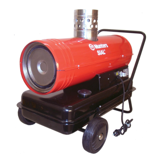
- Page 5 GRY-D General Assembly Outlet Flame Burner Compressor Shield Head Combustion Chamber (open) Motor Fuel Tank...
- Page 6 Fan Motor Assembly US Motors 10 µF 70 W 3300 rpm 2 poles GRY-D 15 100 W 3300 rpm 2 poles 10 µF GRY-D 20 150 W 3300 rpm 2 poles 20 µF GRY-D 28 GRY-I 15 250 W 3300 rpm 2 poles 30 µF GRY-D 40/60 GRY-I 25/40...
- Page 7 Fuel Circuit Vent The fuel circuit is composed of : Pipe fuel tank Fuel fuel suction hose Filter Nozzle Holder fuel filter (air compressor) (air valve) (air hoses) Burner Nozzle nozzle holder (combustion head) Head Fuel ...
- Page 8 Air Compressor Assembly Pressure Adjustment Rear Guard Valve Inlet Filter Pressure Port Cap Filter Casing Gasket Outlet Filter Cover Plate Stator Rotor Air Line to Nozzle Coupling Blade...
- Page 9 Rotary Compressor Rotor Blade Stator Joint...
- Page 10 Air compressor Inlet (Low Pressure) Filter...
- Page 11 Air compressor Outlet (High Pressure) Filter...
- Page 12 Burner Assembly (old and new design)
-
Page 13: Burner Assembly
Burner Assembly Ignition Swirl Electrode Blades Safety Thermostat Combustion Head Nozzle Holder Fuel Nozzle... - Page 14 Combustion Head (current design) Fuel O-ring Seal...
- Page 15 Combustion Head (old design) Washer Spring Washers Rubber Seal...
- Page 16 Nozzle & Nozzle Holder O-ring Fuel Inlet Air Inlet...
- Page 17 STANDARD NOZZLE Pressurized FUEL Inlets Pressurized FUEL Inlets Nozzle Orifice Syphon Nozzle Turbulence Chamber Tangential Channels SYPHON NOZZLE Standard Nozzle Pressurized AIR Inlets Pressurized AIR Inlets Nozzle Orifice Fuel Inlet Fuel Inlet Turbulence Chamber Tangential Channels...
- Page 18 Burner Head on Combustion Chamber...
- Page 19 GRY-D 15 Combustion Head Vent Pipe Nozzle Holder Fuel Filter Burner Head Fuel Nozzle...
- Page 20 GRY-I Combustion chamber detail...
- Page 21 GRY-I Fuel Filter and Air Valve Air Valve Valve Fuel Filter Vent Hole...
-
Page 22: Safety Controls
Safety Controls Flame Sensor and Thermostat • Flame Sensor (Photoresistor) – Detects false flame signals or anticipated ignition – Checks flame failure at ignition – Checks flame failure during operation • Safety thermostat (Limit Control, OPTIONAL for USA models) Limit Flame Control Sensor... - Page 23 Line Fuse...
- Page 24 Safety Controls Air Pressure Switch...
- Page 25 Principle of Operation GRY-D...
- Page 26 Principle of Operation GRY-I...
- Page 27 Ignition Sequence GRY-D 15/20/28/40 6 sec XX sec 0 sec work end SWITCH MOTOR TRANSFORMER PHOTOCELL FLAME AIR PRESSURE SWITCH START TIME WORK TIME...
- Page 28 Ignition Sequence GRY-D 60 & GRY-I 15/25/40 10 sec 16 sec 45 sec 0 sec SWITCH work end MOTOR TRANSFORMER AIR SOLENOID VALVE PHOTOCELL FLAME AIR PRESSURE SWITCH PREVENTILATION TIME START TIME WORK TIME POST-VENTILATION TIME...
- Page 29 Wiring Diagrams...
- Page 30 Wiring Diagrams...
- Page 31 GRY-D GRY-I Service Procedures...
- Page 32 Rotor-Stator Clearances...
- Page 33 Correct Stator vs. Rotor Positioning 0.5 mm (0.2”) spacer plate Stator Fixing Screws...
- Page 34 Air pressure adjustment Pressure Adjusting Screw Pressure Gauge )
- Page 35 GRY-D Appearance of front disc BAD COMBUSTION GOOD COMBUSTION...
- Page 36 Ignition Electrode Gap...
- Page 37 Electronic control boards GRY-I GRY-D...
- Page 38 Pressure Adjustment Valve Screw Spring Ball Gasket...
- Page 39 Air Ducting (Indirect Heaters only) GRY-I 25&40 WU Max Duct Lenght ~ 8 m (25 ft) GRY-I 15 WU Max Duct Lenght ~ 6 m (20 ft)
- Page 40 Draining Fuel from Tank...
- Page 41 Fuel Suction Hose Hose Gasket Bottom Spacer (important!)
- Page 42 Tank Cap...
- Page 43 Typical Air Temperatures on Direct and Indirect Heaters 1200°F 300°F 190°F 600°F 250°F 140°F 100°F...
- Page 44 Service & Maintenance Equipment Measuring devices Electric Multimeter (V, A, ) PC Flame Sensor Tester Kit Pressure Gauge Kit (incl. hose and fitting) Smoke Index Tester...
Need help?
Do you have a question about the SIAL GRY-D Series and is the answer not in the manual?
Questions and answers
Motor will run for 5 minutes and then shuts down
The Munters SIAL GRY-D Series motor may run for 5 minutes and then shut down due to a safety control mechanism, such as the air pressure switch or flame failure detection. If the air pressure switch detects overheating, it shuts the heater down. Additionally, if the flame failure sensor detects an issue at ignition or during operation, the system will also shut down. It is recommended to check and eliminate any cause of overheating or flame failure before restarting the unit.
This answer is automatically generated