Table of Contents
Advertisement
Quick Links
Advertisement
Table of Contents

Related Manuals for HANYOUNG NUX TS500


Summary of Contents for HANYOUNG NUX TS500
- Page 1 Thermal Shock Test Controller MANUAL...
- Page 2 To the Users Thank you for purchasing the product of HANYOUNG NUX. This manual describes the functions of the product, installation methods, precautions, and how to use in detail. Please read and fully understand this manual before using the product.
-
Page 3: Table Of Contents
Table of Contents 1.1 Checking the Product 1 Before Installation 1.2 Precautions on Safety 2.1 Where to Install and Precautions 2 How to Install 2.2 How to Install 2.3 Type Composition 2.4 Appearance and Panel Processing Dimensions 2.5 Connection Diagram 2.6 How to Connect 3.1 Main Screen 3 Control and Setup... -
Page 4: Before Installation
1 Before Installation Thank you for purchasing thermal shock test controller (model : TS500) of HANYOUNG NUX. This user’s manual describes the functions of the product, installation methods, precautions, and how to use in detail. Please read and fully understand this manual before using the product. In addition, please let this manual be conveyed to and used by the final user, and keep it where you can read it at any time. -
Page 5: Precautions On Safety
1.2 Precautions on Safety 1.2.1. Precautions on Safety •For the protection and safety of the product and the system connected to the product, please use the product following the safety instructions on this manual. • We shall not take responsibility about any safety issue or losses occurring due to the use or handling of the product not following the instructions of this manual or any carelessness. -
Page 6: How To Install
2 How to Install Below is an explanation on where and how to install TS500 (Thermal Shock Test Controller). Please read before installation. 2.1 Where to Install and Precautions 2.1.1 Where to Install • As there is a danger of electric shock, please use this product installed on the panel. - Page 7 • First check if the main power supply is blocked, and then perform wiring. • Install a switch to separate TS500 from the main power supply at the power line. • Connect a fuse of about 2 A to the power line.
- Page 8 2.3 Suffix Code Model Code Description TS500 - Thermal Shock Test Controller Without main frame (when needing only I/O Module) Main Frame Main Frame (RS232, RS485) N Without I/O Module (when needing only the main frame) I/O Module...
-
Page 9: Connection Diagram
2.4.2.I/O Module [Unit : mm] 250.0 238.0 65.0 225.0 37.5 2.5 Connection Diagram 2.5.1 Connection Diagram of Main Frame Communication Output RS232 TXD GND Control Output & RS232 Communication Output Retransmission Output RS485 RTX(+) R TX ( ) CTL.OUT H.OUT (High Temp. - Page 10 2.5.2 Connection Diagram of I/O Module Digital Input Power Supply Output Power Supply Output 24 V d.c 200 mA Max. D.I 1 D.I 2 D.I 3 D.I 4 D.I 5 D.I 6 D.I 7 D.I 8 ※ In case of transistor input D.I 9 D.I 10 D.I 11 D.I 12 D.I 13 D.I 14 D.I 15 D.I 16 Power Supply Input...
-
Page 11: How To Connect
100 - 240 V a.c RET - 50 / 60 Hz L.OUT + 2.6 How to Connect L.OUT - ※ Please refer to 2.5 Connection Diagram. 2.6.1 Power Supply Perform third-class grounding or over (grounding resistance of 100 Ω or less) with electric wires of 2 ㎟... - Page 12 2.6.7 Communication Wiring ● Wiring of RS485 TS500 can be connected to up to 256 units. Connect terminating resisters (100 – 200 Ω 1 / 2 W) to the both ends of the communication line without fail. RTX(+) RTX(+) RTX(-)
-
Page 13: Control And Setup
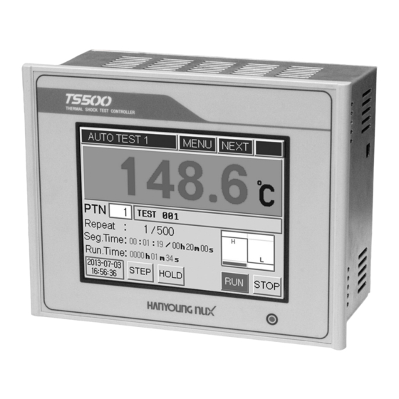
3 Control and Setup 3.1 Main Screen Apply the power supply to the product, and the logo screen gets indicated for around three seconds, and the operation screen gets indicated. (You can change the logo screen by using the communication function.) [Fig. - Page 14 3.2.1 Number Input Screen You can input whole numbers and real numbers (with a decimal point) into the Number Input Screen [Table 3]. On the top left, the inputted contents and the maximum and minimum are indicated the currently inputted value is indicated on the input window above the numeric keypad the inputted number will be stored only when you press the button and if you press the button...
-
Page 15: Name Of Each Part Of Operation Screen
[Fig. 6] English (Capital Letter) Input Screen [Fig. 7] English (Small Letter) Input Screen 3.3 Name of Each Part of Operation Screen ③ ① ② ④ ⑤ ⑥ ⑨ ⑦ ⑧ ⑩ ⑪ ⑫ ⑬ ⑭ [Fig. 8] Operation Screen 1 (Automatic Mode) Name Name ①... - Page 16 ① ② ③ ⑤ ④ ⑥ ⑧ ⑦ ⑨ ⑮ ⑩ ⑪ ⑫ ⑬ ⑭ [Fig. 9] Operation Screen 1 (Manual Mode) Name Name ① Current Screen Information Window ⑨ Indication of Control Output of Low Temp. Room ② Menu Entry Button ⑩...
- Page 17 ① ② ③ ④ ⑥ ⑤ ⑰ ⑦ ⑯ ⑧ ⑨ ⑩ ⑪ ⑫ ⑬ ⑭ ⑮ [Fig. 10] Operation Screen 2 (Automatic Mode) Name Name ① Current Screen Information Window ⑩ AL (Alarm) Status Indication Window ② Menu Entry Button ⑪...
- Page 18 ① ② ③ ④ ⑦ ⑥ ⑧ ⑤ ⑨ ⑩ ⑯ ⑮ ⑰ ⑱ ⑲ ⑪ ⑫ ⑬ ⑭ [Fig. 11] Operation Screen 2 (Manual Mode) Name Name ① Current Screen Information Window ⑪ Event Information Checking Button ② Menu Entry Button ⑫...
- Page 19 ① ② ③ ④ ⑪ ⑫ ⑬ ⑤ ⑭ ⑧ ⑨ ⑥ ⑮ ⑦ ⑩ ⑯ ⑰ [Fig. 12] Operation Screen 3 (Automatic Mode) Name Name ① Current Screen Information Window ⑩ Time of One Grid ② Menu Entry Button ⑪...
- Page 20 ① ② ③ ④ ⑪ ⑫ ⑤ ⑧ ⑨ ⑬ ⑥ ⑭ ⑮ ⑦ ⑩ ⑯ ⑰ [Fig. 13] Operation Screen 3 (Manual Mode) Name Name ① Current Screen Information Window ⑩ Time of One Grid ② Menu Entry Button ⑪...
-
Page 21: Automatic Operation
3.4 Automatic Operation Automatic operation means the operation mode that automatically controls the system following the test pattern programmed in advance, the SVs of pre-heating/test of each room, test time, and the signals of a variety of fans, elevator, damper, gas, freezer, and valve get automatically created following the determined patterns, and all the processes of general thermal shock tests get automatically performed. -
Page 22: Manual Operation
3.5 Manual Operation Manual operation means the mode of constant value operation of the High Temp. room and the Low Temp. room with respectively determined SV. In general, it performs the motions of two-channel thermostat, and you must designate the output of other control signals in person. - Page 23 ● Manual Signal Output Press the button at the bottom of the [Fig. 20] manual operation screen, and the [Fig. 22] manual signal output screen is indicated. Turn the output signal ON or OFF by using each button. Button Details When it is designated at the DI-3, 4 that the sensor for sensing the location of elevator is connected, the output automatically turns OFF following the input of the pertinent sensor.
-
Page 24: Graph Indication And Setup
The data maximum for three days, which is used for graph indication is automatically stored in the memory in TS500. The data will be deleted when the power turns off. The rectangular boxes inside the graph screen are hidden buttons of the screen movement and expanding/reducing functions. And... -
Page 25: Indication Of Errors And Events
3.7 Indication of Errors and Events The Automatic and Manual Second Operation Screen indicates the detailed status of signal input and output of the system. ● Indication of event details You can check the details of occurrence of errors by sensor disconnection and the external input (DI) by pressing the button at the center bottom of the operation screen and can check a variety of events including the operation start/end, input of power supply, and details of occurrence of errors. -
Page 26: Screen Block Diagram
4 Screen Composition The screen of TS500 Thermal Shock Test Controller is composed largely of “Operation Screen”, “Function Setup Screen”, and “System Setup Screen”. It is the screen that is firstly indicated when the power gets turned ON is Operation Screen composed of ①... - Page 27 Category Screen Composition Setup Details Sensor Input Selection of sensor type and setup of input filter Setup 1 Sensor Input Sensor IN Setup of voltage range and scale at the time of voltage input Setup 2 Sensor Input Setup of range of temperature used and input correction Setup 3 Control Output Selection of output type and setup of ON/OFF control dead...
-
Page 28: Operation Screen
4.2 Operation Screen [Fig. 28] Operation Screen 1 (Automatic Mode) [Fig. 29] Operation Screen 1 (Manual Mode) [Fig. 30] Operation Screen 2 (Automatic Mode) [Fig. 31] Operation Screen 2 (Manual Mode) [Fig. 32] Operation Screen 3 (Automatic Mode) [Fig. 33] Operation Screen 3 (Manual Mode) -
Page 29: Function Setup Screen
4.3 Function Setup Screen Press the button at the top in the operation screen, and the [Fig. 35] Setup Menue Screen is indicated. You can set basic items related to Operation in the Setup Menue Screen. [Fig. 34] Operation Screen [Fig. - Page 30 5 Function Setup 5.1 Function setup Press button in the [Fig. 35] Setup Menu Screen, and the Function setup 1 Screen is indicated. [Fig. 37] Function setup 1 Screen [Fig. 38] Function setup 2 Screen ● Function setup 1 Operating Mode Select the motion mode by pressing the Auto or the Manual button.
-
Page 31: Pattern Setup
5.2 Time & Reserve Setup Press button in the [Fig. 35] Setup Menu Screen, and the Time & Reserve Setup Screen is indicated. You set the date and time of the system. If you set the time for reserved operation, the reservation mark, which shows the reserved operation waiting status, flickers in the Operation Screen (it is not indicated during operation) if the product is stopped at the reserved time, it starts operation automatically (with the power supply applied). - Page 32 ● Pattern Setup 1 Select the pattern number you want to set. (1 – 240) Rept Repeat count (1 – 9999 times if you set 9999, the repetition is limitless.) Link The test pattern number to be connected and operated. (0 or 1 – 240) Selection of : Operation gets performed for the repeat count that is set, END Mode...
- Page 33 ● Test Type Code Test Type Code Test Type ① ⑥ ② ⑦ ③ ⑧ ④ ⑨ ⑤ ⑩ ● Pattern Setup 2 You can set the test name by pattern, waiting range/time, auto defrost cycle, and temperature and time of auto defrost in the [Fig. 43] Pattern Setup 2 Screen. [Fig.
- Page 34 ● Setup Items Record of the name of test pattern to be indicated in the Operation Screen. Name (Korean/English/numbers available) •Setup of the temperature range and time to be used for the compared motion at the time of activation of the waiting motion •For the temperature range, <PRE ±...
-
Page 35: Lcd Brightness Adjustment
5.4 LCD Brightness Adjustment The brightness of LCD can be adjusted in 8 stages in total press the right side of the button, and it gets brighter by stage and press the left side of the button, and it gets darker by stage. The current brightness is indicated in the shape of a bar. -
Page 36: Sensor Input Setup
6.1 Sensor Input Setup ● Selection of Sensor Type (Sensor Input Setup 1) TS500 Thermal Shock Test Controller supports the three points of measurement input (the High Temp. Room/Test Room/Low Temp. Room). The input (sensor) specifications support the thermoresistor (Pt 100 Ω), thermocouple, and DC voltage (current) input with multi-input and you can set the input filtering time. - Page 37 [Fig. 48] Sensor Input Setup 1 Screen [Fig. 49] Sensor Input Setup 2 Screen ● Input Correction (Sensor Input Setup 3) The correction function has the entire OFF SET setup and the function of setup by section the set value of OFF SET and the correction value by section are applied by being added to each other the range of use refers to the range, in which the SV input is limited for the protection of the equipment.
- Page 38 6.2 Control Output / Retransmission Output Setup TS500 Thermal Shock Test Controller supports two points of control output (the High Temp. Room/the Low Temp. Room) and one point of retransmission output. You can choose between SCR (current), SSR, and relay for each control output of the main frame when you choose the relay output, the relay built in the Input •Output board (I.O Board) is applied.
-
Page 39: Alarm Setup
● Setup of Transmission Output by Item Item Details Transmission of measured temperature of the Test Room T.PV PV of Test Room (Test room-PV) (specimen) Transmission of the SV of test. T.SV SV of Test It is outputted only during the operation in the automatic mode. - Page 40 ● Alarm Setup Check of alarm status at all times Alarm Check Check of alarm status only during operation Select the subject of measurement among HIGH (the High Source of Alarm Temp. Room), LOW (the Low Temp. Room), and TEST (the (SOURCE) Test Room).
-
Page 41: Inner Signal Setup
IS 6.5 PID Setup The PID control parameter of TS500 (Thermal Shock Test Controller) can be applied by being divided into up to four areas respectively in each of the High Temp. Room and the Low Temp. Room. The areas are divided by setup three boundary values of each area, and you can control by applying the gain optimized for each area. - Page 42 It means the temperature range, in which the output calculated comes to fall within 100 %, in the control that determines the output in proportion to the deviation between the SV and the PV. Proportional Band When the proportional band is wide, the control output on the deviation is small (P-Band) thus it takes longer to reach the SV when the proportional band is narrow, the control output is large thus it takes shorter to reach the SV, but the overshoot...
- Page 43 When the control performance of the PID gain, which is automatically created after auto tuning, is not satisfactory, this indirectly controls the ratio of reflection Auto Gain of the integral/derivative time applied again. When this is set to be bigger than (A.T GAIN) one, it takes longer to reach the SV, but the overshoot and hunting range is decreased when this is set to be smaller than one, it takes shorter to reach the...
- Page 44 6.6 Digital Input (DI) Setup Every external digital input (DI) basically has the function of “error input warning and operation stop”. When is set, it comes to only performs the function of error input warning (always sensing) when is set, it also performs the function of operation stop when an error input occurs. ①...
- Page 45 [Fig. 67] and [Fig. 68] are the screens in which you can set the name of digital input (DI) press the input window, and the input keyboard is indicated input the name of digital input changing the keyboard by pressing the keyboard converting button input a name that you can intuitively identify when an error occurs.
- Page 46 6.7 Digital Output (DO) Setup The digital output setup is to actually allocate various signals occurring in the system to the relay or transistor output. Only the signals allocated here are output through the actual terminal and, the allocation of the output number can be overlapped, thus you have to carefully input it. Depending on the characteristics of each signal output, sometimes you have to designate only the output number and other times you have to set the parameter of time or value of temperature along with that.
- Page 47 [Fig. 71] Digital Output Composition Setup [Fig. 72] Digital Output Composition Setup 3 Screen (DO Setup 3) 4 Screen (DO Setup 4) ● Digital Output (DO) Composition Setup 3 Discrete Output Item Details Damper in the High Temp. H.Damper OPEN Room is opened Damper in the High Temp.
- Page 48 ● Digital Output (DO) Composition Setup 4 – 9 It is a screen of setup the input/output signal logic calculation function can program up to 30 lines. The logic calculation is performed in order from Line 1 through Line 30. (Press the button with a number indicated, and the pertinent line is activated.) [Fig.
-
Page 49: Communication Setup
It supports the protocol of the Modbus-ASCII method. TS500 Thermal Shock Test Controller always works as a slave on the communication protocol, and the host side needs a program for communication. You can choose RS232 or RS485 as the port for serial communication you also can select and set the up/down arrow buttons and boxes in person for the items including the communication speed, device number (1 –... - Page 50 6.9 ETC Setup [Fig. 76] ETC setup 1 [Fig. 77] ETC setup 2 ● ETC Setup 1 [Fig. 76] Language Select the language used in the menu. Set the password needed when entering the System Setup menu. Password (When it is the default value of “0”, the product does not ask the password when you enter the System Setup menu.) Set the type of chamber.
-
Page 51: Measurement Input Specifications
7 Specifications 7.1 Measurement Input Specifications Pt100 Thermoresistor -200.0 ℃ ~ 640.0 ℃, ± 0.1 % of F.S (IEC751) -200.0 ℃ ~ 1370.0 ℃, ± 0.1 % of F.S -200.0 ℃ ~ 1200.0 ℃, ± 0.1 % of F.S -200.0 ℃ ~ 1000.0 ℃, ± 0.1 % of F.S Thermocouple -200.0 ℃... -
Page 52: I/O Module
7.2 Control Output/Transmission Output Specifications 4 – 20 mA DC (Load resistance of 600 Ω or lower) Current Output resolution : 16 bit Output Output degree : ±0.1 % of F.S (SCR) Output ripple : 0.1 % of F.S Control Voltage 24 V DC Pulse (load resistance of 600 Ω... -
Page 53: Function Specifications
7.6 Function specification Display 5.7 inch color LCD panel with touch screen Applicable chamber Elevator type, damper type, gas type etc. Test pattern Max 240 patterns, selectable 10 test kinds of each pattern. stanby mode Each pattern setup and setup of using each segment Repetition and connection The number of repetition can be set up and connected driving PID control or ON/OFF control in high-temperature room and low- PID group... - Page 56 28, Gilpa-ro 71beon-gil, Nam-gu, Incheon, Korea TEL : (82-32)876-4697 FAX : (82-32)876-4696 http://www.hynux.net E-mail. overseas@hynux.com...
Need help?
Do you have a question about the TS500 and is the answer not in the manual?
Questions and answers