Table of Contents
Advertisement
Quick Links
¢ˇ
¢ˇ
A / S¯ ‹ • ˛ „ ... › " æ ‰ "
: 080-979-1010
HEAD OFFICE
1381-3, Juan-Dong, Nam-Gu Incheon, Korea
TEL: (82-32)876 - 4697 FAX : (82-32)876 - 4696
http://www.hynux.com E-mail. sdt@hynux.com
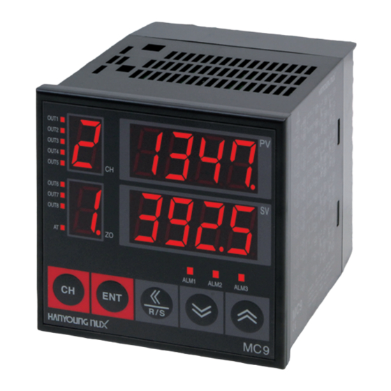
MC9 series
Multi-channel Temperature Controller
T T h h a a n n k k y y o o u u v v e e r r y y m m u u c c h h f f o o r r p p u u r r c c h h a a s s i i n n g g H H A A N N Y Y O O U U N N G G p p r r o o d d u u c c t t . .
P P l l e e a a s s e e r r e e a a d d t t h h i i s s m m a a n n u u a a l l c c a a r r e e f f u u l l l l y y a a n n d d k k e e e e p p t t h h i i s s f f o o r r f f u u t t u u r r e e u u s s e e . .
M A N U A L
Advertisement
Table of Contents

Related Manuals for HANYOUNG NUX MC9 Series


Summary of Contents for HANYOUNG NUX MC9 Series
- Page 1 MC9 series Multi-channel Temperature Controller M A N U A L T T h h a a n n k k y y o o u u v v e e r r y y m m u u c c h h f f o o r r p p u u r r c c h h a a s s i i n n g g H H A A N N Y Y O O U U N N G G p p r r o o d d u u c c t t . .
- Page 2 Every t i t l e , sy m bols, figures, service marks, and etc. in this guide or the product are l egally registered. HANYOUNG NUX #1381-3, Juan 5-dong, Nam-gu, Incheon, Korea TEL: +82 32 876 4697 FA X: +82 32 876 4696...
-
Page 3: Table Of Contents
‚æ ´ 1 BEFORE STA RTING Thanks for purchasing Multi-channels temperature Controller. 1-1 Check contents 1 1 B B e e f f o o r r e e S S t t a a r r t t i i n n g g 1-2 Safe ty Information This manual shows how to install and use. - Page 4 1 - 2. SAFETY NOTICE ¡Æ Safety notice for this user manual - Under following conditions, repair will be charg ed even during warranty period. - Please make this manual to be delivered to the final user and to be placed where - Breakdowns due to user’s misuses can be found and seen easily.
- Page 5 § § S S u u f f f f i i x x C C o o d d e e o o f f 8 8 c c h h a a n n n n e e l l s s 2 …...
-
Page 6: Input Type & Range Code
2 - 2. Input Type & Range Code 2 - 3. Rating Input Ty pe Range Code (¡ ) C od e Items D escription -200 ~ 1370 Power Voltage 100 - 240 V a.c, (50 - 60 Hz) (¡ 10 %) -199.9 ~ 999.9 Consumption Maximum 4W... -
Page 7: Terminal Arrangement
2 - 5. Terminal Arrangement Alarm 1, 2, 3 : 250 V a.c, 1 A (Resistive Load) HBA : Current Tr ansformeter(CT ) ) Alarm Output 0 ~100 A (J&D ELETRONIC. Co., Ltd) § § C C o o n n n n e e c c t t i i o o n n s s Extent : ¡... - Page 8 § § O O u u t t p p u u t t 1 1 ( ( o o u u t t 1 1 ~ ~ 4 4 ) ) § § O O u u t t p p u u t t 2 2 ( ( o o u u t t 5 5 ~ ~ 8 8 ) ) §...
-
Page 9: Name & Function
2 -6. Name & Function Basic Operation ① ¤ : Window for displaying Channel ( ¡ A¡– Batch Setting) ¤Ł : Indicate Lamp(Output 1~8,AT) 3 - 1. Flowchart of Parameter ¤Ø : Window for displaying Memory Zone ② ⑪ (Display Memory Zone) ENT + <<... - Page 10 3 - 3. Monitor Display 3 - 2. Parameter Range & Initial Value Signal Range Unit N a m e Initial Value A re a EU(0 ~ 100 %) Set Value EU(0 %) § § A B S ZO N E Memory Zone 1 ~ 8 §...
- Page 11 3- 4. Operation Mode 3 - 5. Function Mode I f you press ENT key in monitor screen for 2 sec. , it enters into Function mode. Set SV & Zone to control. Also you can check HBA value in case of HBA option. Generally users create setting value easily on occasion in selecting function mode.
- Page 12 § LBD : Control Loop Break Alarm Deadband § ” æ • ˚ · º (PB : Pro portional Band) Initial Value : Voltage input : 0 ¡ , 0.0 ¡ Setting range : 0 ~ 100 sec Initial Value : 30 ¡...
- Page 13 § Anti Reset Windup 3 - 6. SETUP MODE) Initial Value : 0 (Auto) Setting range : 0 (Auto) ~ 100 % I f you press ENT key + key in the monitor screen or Function mode, you can enter Contents : Set the range of valid operation in into Setup mode.
- Page 14 § HBA : Heater Break Alarm 1 § FR-L : Range Low Limit Initial Value : OFF I n i t i a l value : Lower of input range Setting range : 0.0 ~ 100.0 A Setting method : Set the lower of input ~ FR-H Contents : I f you choose HBA option &...
- Page 15 § F i l t e r § PRI : Pa r i ty I n i t i a l value : OFF I n i t i a l value Setting range : 0 ~ 120 s Setting range : 0 ~ 2 Contents : Set the first time of delayed filter to...
- Page 16 § ˙ ¥ ‰ ˆ £ ‰ ˆ £ (SCAN : Scan Interval Time) 4 Setting Method I n i t i a l value : 2 s Setting range : 1 ~ 100 s Contents : Set time until current displayed channel 4 - 1.
- Page 17 § § W W h h e e n n y y o o u u d d e e c c r r e e a a s s e e d d S S V V v v a a l l u u e e ( ( C C h h a a n n g g i i n n g g 4 4 0 0 0 0 t t o o 3 3 9 9 0 0 ) ) §...
- Page 18 § § W W h h e e n n y y o o u u s s e e t t a a l l l l S S V V a a t t t t h h e e s s a a m m e e t t i i m m e e [ [ ¡ ¡ A A ¡ ¡ – – ] ] 5 Explanation of Functions Set SV in channel 1~8 from 0C to 200C at the same time.
- Page 19 § ‰ ˙ ˙ 5 - 3. ALARM Alarm will act as a ¡ O R¡– condition against all channels. I f you press key, parameter which can operate (* OR condition : If any channel out of total 8 channels exceed ed alarm setting value, Auto-Tuning will show up as left picture .
- Page 20 § Alarm operation § § A A l l a a r r m m h h y y s s t t e e r r i i s s i i s s ¡⁄ High¡⁄ Low deviation alarm Alarm type Alarm operation Alarm type...
- Page 21 § § L L B B A A 5 - 4. Multi - Memory Zone If PV value is within P band, LBA does not operate. After it is out of P band, LBA begins to operate. LBA operation There are 8 channels in MC9 and each channel In case output is 0% and control direction is direc t 메모리존...
- Page 22 5 - 5. SCAN 5 - 6. RUN/STOP Set time to display the window of PV/SV from channel 1 to channel 8 one after the other. This mode is to operate an instrument after it is finished that initial parameter setting of contro l 2 sec 2 sec...
- Page 23 6 - 2. Output 6 ` ƒ ˙ » § ` ƒ ˆ • ´ 6 - 1. Input Items Description Contact : 1a Contact capacity : 250 V a.c, 3A(Resistive load) Relay Output operation : P.I.D control, On/Off Pro portional cycle : 1 ~ 1000 sec. Time resolution : Smaller one between 0.1 % and 10 ms ƒU Input &...
- Page 24 6 - 3. Communication Application Standard Based on EIA RS485 Max. Contact Points 31 points or 255 points Communication Method 2 Wire half duplex or 4 Wire half duplex Synchronization Start-Stop synchronous Mod e Communication Sequence None Communication Distance 1.2Km max. Communication Spe e d 1200/2400/4800/9600 bps(Speed is changeable by Parameter) start bit...
Need help?
Do you have a question about the MC9 Series and is the answer not in the manual?
Questions and answers