Advertisement
Quick Links
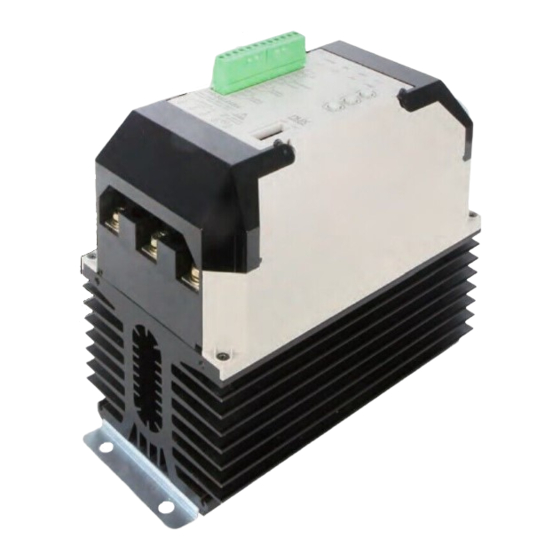
Power REGULATOR
TPR-3SL
INSTRUCTION MANUAL
Thank you for purchasing HANYOUNG product.
Please check whether the product is the exactly same as you ordered.
Before using the product, please read this instruction manual carefully.
Please keep this manual where you can view at any time
Safety information
Before using the product, please read the safety information thoroughly and use it properly.Alerts declared in the manual
are classified to Danger, Warning and Caution by their criticality
DANGER
DANGER indicates an imminently hazardous situation which, if not avoided, will result in death or serious injury
WARNING indicates a potentially hazardous situation which, if not avoided, could result in death or serious injury
WARNING
CAUTION
CAUTION indicates a potentially hazardous situation which, if not avoided, may result in minor or moderate injury
Danger
To prevent electric shock while it is running, put to earth with the fixed screw of the unit and do not touch the radiator
panel since it is very hot. Do not touch or contact the input/output terminals because they cause electric shock.
Warning
•Please install appropriate protective circuit on the outside if malfunction or an incorrect operation may be
a cause of leading to a serious accident.
•If you use the product with methods other than specified by the manufacturer, there may be bodily injuries
or property damages.
•Since this product is not designed as a safety device if it is used with systems, machines and equipment
that could lead to a risk of life or property damage, please implement safety devices and protections for
both lives and the applications and plan for preventing accidents.
•To prevent damage or failure of this product, please supply the rated power voltage.
•To prevent electric shock or equipment failure, please do not turn on the power until completing wiring.
•Never disassemble, modify, or repair the product. There is a possibility of malfunction, electric shock,
or a risk of fire.
•Please turn off the power when mounting / dismounting of the product. This is a cause of electric shock,
malfunction, or failure.
Caution
•Since the product operating environment influences the product performance and expected life span,
please avoid using in the following places.
2-50
· a place where humidity is high and air flow is inappropriate.
4-6.5
· a place where dust or impurity accumulates, ambient temperature is high and vibration level is high.
· a place where corrosive gas (such as harmful gas, ammonia, etc.) and flammable gas occur.
· a place where there is direct vibration and a large physical impact to the product.
· a place where there is water, oil, chemicals, steam, dust, salt, iron or others (Contamination class 1 or 2).
· a place where excessive amounts of inductive interference and electrostatic and magnetic noise occur.
· a place where heat accumulation occurs due to direct sunlight or radiant heat.
•Please do not wipe this product with organic solvents such as alcohol, benzene and others. (Please use mild detergent)
•Please make sure to inspect the product if exposed to water since there is a possibility of electric leakage or a risk of fire.
•Please connect the product and other units after turning off all the power of the product, instruments and units.
•Please make sure that the power control (TPR) is installed perpendicularly.
•Please install the product inside of the control panel and install an exhaust fan onto the top of the control panel.
•Pay attention to the edge of heat sink which is sharp.
Suffix code
Model
Code
TPR-3SL
-
Slim type 3-phase power regulator
110
040
40 A
055
55 A
070
70 A
Rated current
090
90 A
130
130 A
160
160 A
L
100 - 240 V AC (Low)
Power supply voltage
H
380 - 440 V AC (High)
-
FUSE is installed
Option
N
No Fuse
※ Circuit and FAN need 100 - 240 V AC voltage power separately.
Specification
Low
TPR-3SL040L
TPR-3SL055L TPR-3SL070L TPR-3SL090L TPR-3SL130L TPR-3SL160L
Model
High
TPR-3SL040H TPR-3SL055H TPR-3SL070H TPR-3SL090H TPR-3SL130H TPR-3SL160H
Power supply voltage
Circuit input power
Power frequency
Rated current
Applying load
Current input
Voltage input
Control
Input
Contact input
External V.R
Control method
Phase control, Fixed Cycle control, Variable Cycle control, ON/OFF control
Movement type
Output voltage
More than 98 % of the power supply voltage (In case of maximum current input)
Cooling method
Natural cooling (40 A, 55 A), Forced cooling (70 A, 90 A, 130 A, 160 A)
Display method
Insulation resistance
Min 100 MΩ (Base on 500 V DC mega)
Output control range
Dielectric strength
Line noise
Ambient temperature
Ambient Humidity
Storage temperature
Weight
4,044 g
213.7
194.6
Information
100 - 240 V AC (Low)
380 - 440 V AC (High)
100 - 240 V AC
50 Hz / 60 Hz (Dual usage)
40 A, 55 A, 70 A, 90 A, 130 A, 160 A
Resistive load
4 - 20 mA DC (Impedance : 100 Ω)
1 - 5 V DC
ON / OFF
External volume (10 ㏀)
SOFT START, SOFT UP/DOWN
Display by LED
0 ~ 100 %
3000 V AC 50/60 Hz for 1 min
Noise by noise simulator (2,500 V)
0 ~ 40 ℃ (Without Condensation)
30 ~ 85 % RH
-25 ℃ ~ 70 ℃
4,324 g
9,100 g
HANYOUNGNUX CO.,LTD
28, Gilpa-ro 71beon-gil, Nam-gu, Incheon, Korea
HEAD OFFICE
TEL : (82-32)876-4697
FAX : (82-32)876-4696
http://www.hynux.com
PT. HANYOUNG ELECTRONIC INDONESIA
JL.CEMPAKA BLOK F 16 NO.02 DELTA SILICON II INDUSTRIAL PARK
INDONESIA
LIPPO CIKARANG CICAU, CIKARANG PUSAT, BEKASI INDONESIA 17550
FACTORY
TEL : 62-21-8911-8120~4 FAX : 62-21-8911-8126
Appearance
▒ 40/55/70 A
2-50
4-6.5
110
▒ 90/130/160 A
173
160
Connection diagram
▒ Connection diagram of load terminal
INPUT
· Inside of TPR, the fuse is installed in the R,S,T input power supply
portion depending on the specification of options
· When connecting terminals, please use crimp connectors and
securely fasten them due to the high current flow.
(Max space for solder less terminal connection is
LOAD
▒ Connection diagram of signal and alarm terminal
3
213.7
194.6
H1
70 A (With cooling fan)
249.5 mm
239.1
220.5
40/55/70 A : 16 mm, 90/130/160 A : 26 mm)
• No. ①, ② and ③ : manual V.R
· Use variable resistor of 10 ㏀
· Control 0 ~ 100 % manually
• No. ④ and ⑥ : RUN/STOP
· Be sure to attach RUN contact while it is operating.
• No. ⑤ and ⑥ : ON/OFF control
· When inputting contact, it is operated with 100% output,
irrespective of other control input.
• No. ⑦, ⑧ and ⑨ : Alarm 1 - Warning
This is a "warning" alarm which implies that there may be a
cause of damage to the product and load. At this moment,
TPR stops the output by itself and "warning" alarm is activated.
· Warning error : Overcurrent, SCR short-circuit,
Fuse Disconnection, Power problem
• ⑩, ⑪, ⑫: Alarm 2 (Caution)
This is a "caution" alarm which implies there is not a serious
problem, but user needs to check for its system because small and
minor problems cause this alarm. At this moment, the output of TPR
is normally operating but only "caution" alarm is activated.
· Caution error : Load unbalance, load disconnection,
overheated heat (65 ℃)
• Initially ⑦ & ⑧ connect. If alarm 1 is activated, ⑧ & ⑨ will be connected.
• Initially ⑩ & ⑪ connect. If alarm 2 is activated, ⑪ & ⑫ will be connected.
MB0601KE140806
[Unit : mm]
H2
263.5 mm
125
Advertisement

Related Manuals for HANYOUNG NUX TPR-3SL


Summary of Contents for HANYOUNG NUX TPR-3SL
- Page 1 MB0601KE140806 Power REGULATOR TPR-3SL HANYOUNGNUX CO.,LTD 28, Gilpa-ro 71beon-gil, Nam-gu, Incheon, Korea INSTRUCTION MANUAL HEAD OFFICE TEL : (82-32)876-4697 FAX : (82-32)876-4696 http://www.hynux.com Thank you for purchasing HANYOUNG product. PT. HANYOUNG ELECTRONIC INDONESIA Please check whether the product is the exactly same as you ordered.
- Page 2 ▒ Connection diagram of input signal and power terminal ▒ ON/OFF control 25 % Control 50 % Control 75 % Control 100 % Control If ON/OFF contact is ON, then the output is 100 %. ON/OFF always operates near zero point. ·...
Need help?
Do you have a question about the TPR-3SL and is the answer not in the manual?
Questions and answers