Table of Contents
Advertisement
Quick Links
Advertisement
Table of Contents

Related Manuals for HANYOUNG NUX MT100


Summary of Contents for HANYOUNG NUX MT100
- Page 2 All titles, symbols, figures, service marks, etc. in this guide or the product are legally registered company names, service marks, and trademarks. HANYOUNG NUX 28, Gilpa-ro 71beon-gil, Michuhol-gu, Incheon, Korea TEL : +82-1577-1047...
-
Page 3: Table Of Contents
Before You Start 01. Check the Contents 02. Safety Notice 01. Suffix code Installation 01. External Dimension and Panel Cutout 02. Terminal Diagram 03. Names and Functions of Parts Screen & Parameters 01. Screen Layout 02. Monitor Screen Layout 03. Operation Control Setting Screen Layout and Structure 04. -
Page 4: Before You Start
▣ Before You Start Thank you for purchasing MT 100 (Mold Temperature Controller). This chapter ▶ describes the installation of this product and how to use the product. The contents of this chapter are as follows. 1) Check the Contents 2) Safety Notice ■... - Page 5 Components ◈ MT100 Main Unit ▶ Connection cable ▶ ※ Display unit to main unit MT100 Display Unit ▶ Communication cable ▶ ※ For communication option 2 pin terminal : 7 Pieces ▶ MT100 User Manual ▶ 3 pin terminal : 1 piece ▶...
-
Page 6: Safety Notice
■ 02. Safety Notice Safety notice for this user manual ◈ Please make this manual is delivered to the end user and is placed where it can ▶ be easily found. Please install and operate this product after reading and fully understanding the ▶... - Page 7 Notice about quality assurance conditions ◈ The warranty for this product is valid for one year from purchase and we will fix ▶ any breakdown and faults from proper uses as it is mentioned in this manual for free of charge. After the warranty period, there will be a charge for repair according to our ▶...
-
Page 8: Suffix Code
■ 03. Model Name and Suffix Code Model Number Description MT100 Mold Temperature Controller No communication Communication RS485 / 422 No pressure check Pressure check Pressure check by input of contact Pressure check by 4-20 mA dc No HB HB Test 3 HB(s) ※... -
Page 9: Installation
▣ Installation ■ 01. External Dimensions and Panel Cutout External Dimensions ◈ Unit : mm ▶ 25.3 23.3 155.0 114.0 130.0 23.3 140.0 Panel Cutout ◈ Unit : mm ▶ 171.0 +0.5-0 145.0 +0.5-0... -
Page 10: Terminal Diagram
■ 03. Terminal Diagram Caution ※ Before connecting cables to the units, turn off the main power of all the units and make sure the cables to be connected are not conducting; then connect the cables to the units. ※ Do not touch the terminals when the power is being supplied to the unit because there is a possibility of electric shock. - Page 11 Main Terminal Wiring Diagram ◈ Sensor Terminal ▶ 1,2,3 : Terminal for mold sensor ▷ 4,5,6 : Terminal for MEDI sensor ▷ 7,8,9 : Terminal for water withdrawal ▷ 10,11,12 : Terminal for water ENTER sensor ▷ 13,14 : Terminal for pressure sensor (4 ~ 20 mA) ▷...
- Page 12 92.00 mm Ø3.20 mm SENSOR Power POWER Test pin RELAY OUTPUT Option Alarm Display connector Suction Pump dir Pump rev 4-20 mA Phase Pressure Water fill POWER input Control CT SENSOR Cool SSR Heat Caution ※ Do not connect cables to TEST PIN.
- Page 13 Display Terminal Diagram ◈ DI TERMINAL(Contact Input Terminal) ▶ 1,2(R/S) : RUN/RESET Contact Input Terminal. ▷ COMM TERMINAL(Communication Terminal) ▶ 1,2,3,4 : RS422/485 Communication Terminal. ▷ 5 : Communication Signal Ground Terminal. ▷ Main CN(Terminal for connection with MAIN) ▶ Please connect the cable that comes with MT 100.
-
Page 14: Names And Functions Of Parts
■ 04. Names and Functions of Parts ※ Following figure illustrates cable connection supposing mold system built as shown below. ⑬ Auto water ENTER valve ⑫ Cooling valve Enter cooling water Return cooling water ⑨ Mold temperature sensor ⑪ Pressure gauge ⑧ ENTER temperature sensor ①... - Page 15 Sensor terminal on main board ◈ Terminals to connect temperature and pressure sensors ◆ ⑨ Terminal to connect temperature sensor of mold part When Mold Key is On, it reads and ▶ controls temperature via the temperature sensor. ④ Terminal to connect temperature sensor Sensor terminal of medium (water) When Mold Key is OFF, reads and...
- Page 16 Input terminal on main board ◈ Input terminal for monitoring system ◆ ② Terminal to monitor overheating Using by connecting temperature limit switch. ▶ When contact is input in this part, it stops control ▶ and alert the user. ⑥ Terminal to monitor directs operation of pump and DI terminal overload When contact is input in this part, it stops control...
- Page 17 Relay terminal on power board ◈ Not in use Relay for alert Relay is ON when an alert occurs. ▶ SUCT ⑩ Relay for suction Turn on suction key to switch on relay . ▶ ⑥ Relay for direct operation of pump PP_D Relay is on when starting control and turn on pump to ▶...
- Page 18 Phase detection terminal on power board ◈ Phase check ③ Connect to R phase for controlling 3 phase. ③ Connect to S phase for controlling 3 phase. ③ Connect to T phase for controlling 3 phase. In case of inappropriate connections for R,S, and T, it ▶...
-
Page 19: Screen & Parameters
▣ Screen & Parameters ■ 01. Overall screen layout Power ON Model MENU Monitor screen Menu screen ▲/▼ MENU MENU Contrast SV screen adjustment screen MENU MENU MV screen ▶ ▶ ▶ ▶ 2. ALARM 3. SENSOR 4. DISPLAY 1. CONTROL ◀... -
Page 20: Monitor Screen Layout
■ 02. Monitor screen layout Stop screen ◈ 28.0 Set value Temperature 28.0 Set value Temperature ℃ Temperature ℃ Unit Temperature Unit 28.0 00.00 Input value 28.0 00.00 Input value 10 / 01 SAT 12 : 00 10 / 01 SAT 12 : 00 Current date Current day Current time... - Page 21 nt time Output mode Operation mode 'Auto' and 'Manual' ' Operating' and 'Tuning' Timer screen ◈ 28.0 ℃ ℃ 0.00 28.0 00.00 ating Scheduled time 12 : 34 'Tuning' Operation starts 12 hours and Shows s 34 minutes later. stop Week Timer screen ◈...
-
Page 22: Operation Control Setting Screen Layout And
■ 03. Control setting screen layout and structure CONTROL ① Ph, Ih, Dh, Th ② Pc, Ic, Dc, Tc ③ MODE MENU Heating setting P Ph : [ 15.0 ] ℃ Heating setting I Ih : [ 240 ] Second Heating setting D Dh : [ 60 ] Second... - Page 23 ■ 04. Output operation screen layout and structure ALARM ① COOL OUT ② HEAT OUT ③ TEMP.HI ALM ALARM ④ TEMP.LO ALM ⑤ PRES.HI ALM ⑥ PRES.LO ALM ALARM ⑦ CUR.HI ALM ⑧ CUR.LO ALM MENU Decided COOL OUT PRES.HI ALM PRES.HI ALM whether to use cooling...
-
Page 24: Sensor Setting Screen Layout And Structure
■ 05. Sensor Setting Screen Layout and Structure SENSOR ① MOLD ② MEDIUM ③ RETURN WATER SENSOR ④ ENTER WATER MENU MOLD RETURN WATER MOLD RETURN WATER SETTING SETTING Pt100 Ω Pt100 Ω K-TYPE K-TYPE J-TYPE J-TYPE MEDIUM ENTER WATER ENTER WATER MEDIUM SETTING... -
Page 25: Operation Screen Layout And Structure
■ 06. Operation Screen Layout and Structure DISPLAY DISPLAY ⑦ MOLD BIAS ① TEMP.DISPLAY ⑧ MEDIUM BIAS ② CUR.DISPLAY ⑨ R.WATER BIAS ③ PRES.RANGE DISPLAY ◀ ④ TEMP.RANGE DISPLAY ⑤ ACCURACY ⑩ E.WATER BIAS ◀ ⑥ TEMP.UNIT ⑪ PRE_HEAT SV MENU Display return Return water temperature... -
Page 26: Time Setting Screen Layout And Structure
■ 07. Scheduling Setting Screen Layout and Structure TIME ① RSV.MODE ② CURRENT TIME ③ WEEK RSV TIME ④ WEEK TIME ⑤ DELAY TIME ⑥ MEDI FILL TM MENU RSV.MODE RSV.MODE for RSV.MODE WEEK TIME setting weekly setting ① No schedule ②... -
Page 27: Option Screen Layout And Structure
■ 08. Option screen layout and structure OPTION ① SUCTION ② COOLING ③ REMOTE OPTION ④ LOCK ⑤ PASSWORD ⑥ ID MENU Decide whether SUCTION LOCK Decide whether to use LOCK to use SUCTION Enter password to access to this screen COOLING Password setting... -
Page 28: Error Info Screen Layout And Structure
■ 09. Error Info Screen Layout and Structure ERROR CHECK ① ERROR MASSAGE ② ERROR DELETE MENU Number of the ① Error No 06 Do you want to latest error ② Error No 02 delete all? ③ Error No 13 ④... -
Page 29: Parameters Reference Table
■ 11. Parameters reference table Monitor screen ◈ Display Name Description Display Initial value screen Medium or mold temperature 0.0 ~ 300.0 ℃ 0.0 ℃ Target value Pressure value - Auto/Manual Auto/Manual control AUTO, MAN AUTO TUNING, Monitor Tuning/Operating Tuning/Operating OPERATING screen OPERATING... - Page 30 Operation control screen ◈ Name Display screen Description Display Initial value Heating Proportional Band 0.0 ~ 300.0 ℃ 20.0 ℃ Heating Integral Time 240 s Ph, Ih, 0 ~3600 s Dh, Th Heating Derivative Time 60 s Heating Control Cycle 0 ~ 100 s Cooling Proportional Band 0.0 ~ 300.0 ℃...
- Page 31 Sensor setting screen ◈ Name Display screen Description Display Initial value MOLD MOLD Mold sensor type MEDIUM MEDIUM Medium sensor type Pt 100 Ω, K, J Pt 100 Ω Return water RETURN WATER RETURN WATER sensor type ENTER water ENTER WATER ENTER WATER sensor type Time/Schedule screen...
- Page 32 Operation screen ◈ Name Display screen Description Display Initial value Return Return temperature temperature display TEMP.DISPLAY 0.0 ~ 300.0 ℃ 0.0 ℃ ENTER ENTER temperature temperature display R phase current R phase current display S phase current S phase current CUR.DISPLAY 0.0 ~ 40.0 A 0.0 A...
- Page 33 Option screen ◈ Name Display screen Description Display Initial value SUCTION SUCTION SUCTION COOLING COOLING Forced COOLING ON/OFF REMOTE REMOTE Communication LOCK LOCK LOCK PASSWORD PASSWORD PASSWORD 0000 ~ 9999 0000 Communication ID 1 ~ 99 Language selection ◈ Description Display Initial value Korean...
-
Page 34: Handling And Operating
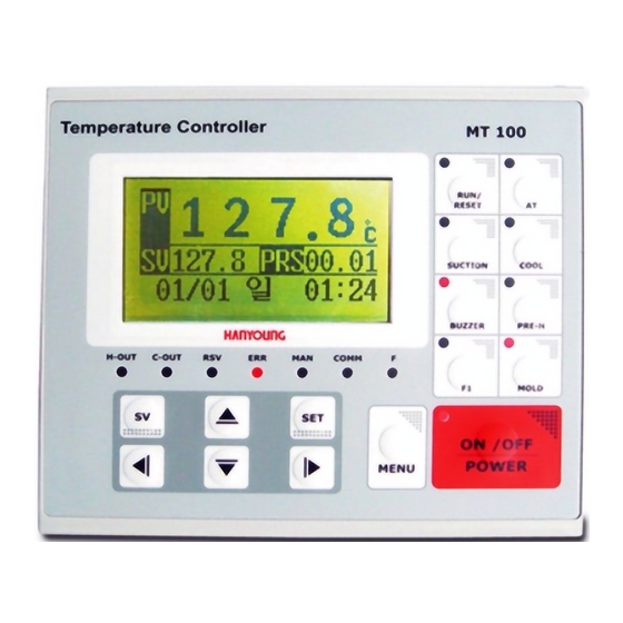
▣ Handling and Operating ■ 01. Front Panel Layout ◈ Display information on LCD screen ▶ ◈ ON/OFF POWER: Key to switch Power ON and OFF ▶ MENU : Key to switch to LCD Screen ▶ SV : Key to change setting value ▶... -
Page 35: Power On/Off
◈ H-OUT : Heating output display LED ▶ MAN : Manual control display LED ▶ C-OUT : Cooling output display LED ▶ COMM : Communication display LED ▶ RSV : Reservation registration display LED ▶ F : Lack of medium alert LED ▶... -
Page 36: Temperature Related Settings
■ 04. Input settings Set temperature input sensor ◈ You can connect 4 temperature input sensors (Mold, MEDI, Return, and ENTER). ▶ You can select one of types (Pt100Ω, K(CA), and J) for each sensor. ▶ Set in "SENSOR" ▶ Set temperature ◈... -
Page 37: Output Setting
■ 05. Output settings Set control output cycle ◈ You can set control cycle of heating or cooling band. ▶ Output works as "Time proportional" operation along with "Control output ▶ cycle". Set in "CONTROL" --> "P, I, D, T" --> "Th" (Heating band) or "Tc" (Cooling band). ▶... -
Page 38: Time Setting
■ 07. Set reservation Set RSV.MODE ◈ RSV.MODE includes "NO RSV", "DELAY TIME" and "WEEK RSV.". ▶ Select "NO RSV" if not using reservation function ▶ When setting RSV.MODE to ""DELAY TIME" or "WEEK RSV.", set time and start ▶ operation to bring up time for "OPERATION START"... - Page 39 WEEK TIME ◈ Start or finish operation on certain day and time on weekly basis. ▶ If current status is operation, it books finishing time otherwise it sets start time. ▶ "RSV" LED flashes when WEEK TIME is set. ▶ In week time mode, "START/DAY/TIME"...
-
Page 40: Auto Medi Filling
■ 08. AUTO MEDI FILL Overview of auto medium filling function ◈ When there is not enough medium in tank, it detects it and start refilling medium. ▶ after refilling medium, it automatically stops filling. Start filling medium ◈ When user runs controller, it checks if contact input is ON in "Input terminal for ▶... -
Page 41: Suction
■ 09. Suction Overview of SUCTION ◈ SUCTION is a function that removes medium such as water or oil on a mold ▶ Once SUCTION starts, "SUCTION RELAY" and "PUMP REVERSE OPERATION RELAY" starts. Start and finish SUCTION ◈ You can start and finish SUCTION by "SUCTION" key or communication ▶... -
Page 42: Pre-Heating
■ 11. Pre-Heating Overview of Pre-Heating ◈ Pre-Heating is a function for freeze protection in winter target value for pre-heat ▶ can be set in Pre-heat SV" on Control screen during pre-heating process, ON/OF control is conducted according to pre-set "Pre-heating SV" (Initial value: 15C). target value for pre-heat can be set in Pre-heat SV"... -
Page 43: Pressure Check
■ 13. Pressure Test Pressure test can be conducted two ways. ▶ Test via terminal input ▷ Test via 4 - 20 mA analog input ▷ Test via terminal input ◈ When terminal input for pressure test is ON, it detects pressure fault, send alert ▶... -
Page 44: Various Functions
■ 14. Various Functions Alarm ◈ The controller provides 6 types of alarm. If one of alarm occurs, alarm relay and ▶ buzzer is ON and register it in "ERROR CEHCK" Alarm for high/low temperature limit ▷ Alarm for high/low pressure limit ▷... - Page 45 LANGUAGE ◈ This controller supports "Korean" "English" "Japanese" and "Chinese". You can ▶ set language in "LANGUAGE". Caution ※ "Japanese" and "Chinese" are currently under development. Buzzer ◈ When an error occurs in controller or system, the BUZZER starts ringing. at the ▶...
-
Page 46: Troubleshooting
■ 15. Trouble shooting Error Causes Alarm Control status SYSTEM ERROR NONE Stop RJC ERROR Holding state ADC ERROR Controller error Stop EEPROM ERROR Holding state BOARD ERROR Stop Holding state Auto tuning is not complete AT ERROR within 24 hours INPUT OPEN Sensor input error Active... - Page 47 ▣ Specification Rated specifications ◈ Division Contents Power 100 - 240 V a.c.(±10 %) 50/60 Hz Temperature 0 ~ 50 ℃ Operating environment Humidity 45 ~ 85 % R.H.(Without condensation) Display 128 x 64 MONO LCD Type Pt 100 Ω, K(CA), J(IC) Number of Input 4 contacts Temperature...
- Page 48 Power specifications ◈ 100 - 240 V a.c. (Operating voltage range:+_10% of rate supply Power supply voltage voltage) Frequency 50/60 Hz Power consumption Max 6.5 W Insulation resistance Above 20 MΩ at 500 V d.c. Measuring terminal - earth terminal : 2300 V a.c. for 1 minute Dielectric strength Power terminal - earth terminal : 2300 V a.c.
- Page 49 Relay output specifications ◈ Number of outputs 1 contact Output type Relay A contact Contact capacity 250 V a.c. 1 A, 30 V d.c. 1 A Measurement accuracy 0.1 % or 16.667 ms whichever is larger Contact input specifications ◈ Number of inputs 1 contact ON/OFF resistance...
- Page 50 MA0631K200427 MT100 28, Gilpa-ro 71beon-gil, Michuhol-gu, Incheon, Korea TEL : +82-1577-1047 http://www.hynux.com...
Need help?
Do you have a question about the MT100 and is the answer not in the manual?
Questions and answers