Johnson Controls 100 Series Installation Operation & Maintenance
Packaged rooftop units, single packaged units, ypal design level g
Hide thumbs
Also See for 100 Series:
- Engineering manual (102 pages) ,
- Installation operation & maintenance (166 pages) ,
- Manual (56 pages)
Table of Contents
Advertisement
Quick Links
Download this manual
See also:
Engineering Manual
Advertisement
Table of Contents

Related Manuals for Johnson Controls 100 Series


Summary of Contents for Johnson Controls 100 Series
- Page 1 PACKAGED ROOFTOP UNITS NEW RELEASE Form 100.50-NOM12 (419) INSTALLATION, OPERATION, MAINTENANCE 035-22722-010 SERIES 100 SINGLE PACKAGED UNITS YPAL DESIGN LEVEL G LD16707 70 THROUGH 105 TONS Issue Date: April 2, 2019...
-
Page 2: Safety Symbols
All wiring must be in accor- dance with Johnson Controls’ published specifications and must be performed only by a qualified electrician. Johnson Controls will NOT be responsible for damage/problems resulting from improper connections to the controls or application of improper control signals. -
Page 3: Changeability Of This Document
FORM 100.50-NOM12 ISSUE DATE: 04/02/2019 CHANGEABILITY OF THIS DOCUMENT In complying with Johnson Controls’ policy for con- regarding the applicability of these documents, rig- tinuous product improvement, the information con- ging, lifting, and operating/service personnel should tained in this document is subject to change without verify whether the equipment has been modified and notice. -
Page 4: Base Model Number
R : Right Supply C : Cooling Only N : Natural Gas Heat G : Natural Gas Heat SS HX M : Modulating Gas Heat E : Electric Heat S : Steam Heat H : Hot Water Heat JOHNSON CONTROLS... -
Page 5: Table Of Contents
Air Hoods For Fixed Outside Air (Units Without Economizer) ................ 29 Air Hoods For Exhaust Air ..........................29 Field Wiring ..............................29 Thermostat ............................29 Space Sensor ............................29 Sensor ............................29 Occupied/Unoccupied Input ........................29 Shutdown Input .............................29 Smoke Purge Input ..........................29 VAV Heat Relay Output .........................30 JOHNSON CONTROLS... - Page 6 Manifold Gas Pressure Adjustment ....................... 49 SECTION 4 – MAINTENANCE ..........................51 General ................................51 Periodic Maintenance – Monthly ........................51 Filters ..............................51 Linkages ..............................51 Compressors ............................51 Fan Bearing Lubrication ........................51 Recommended Lubricant for Fan Bearings ................... 52 Condenser Coils ............................52 JOHNSON CONTROLS...
- Page 7 Compressor Staging ..........................73 Fast Compressor Start ..........................74 Compressor Operation ..........................74 Compressor Status ..........................75 Compressor Safety Circuits ........................75 Resetting a Compressor System Safety Lockout .................. 78 Suction Temperature Monitoring ......................78 High Discharge Pressure Unloading ..................... 79 Low Ambient Inhibit ..........................79 JOHNSON CONTROLS...
- Page 8 Smoke Purge Setup ..........................112 Smoke Purge Sequence of Operation ....................112 SECTION 6 – USER INTERFACE CONTROL CENTER ..................113 User Interface Control Center ........................113 Data Entry Keys ..........................113 Navigation Keys ..........................114 Menu Select Keys ..........................114 JOHNSON CONTROLS...
- Page 9 Building Pressure Transducer ......................166 Return Fan Pressure Transducer ......................166 Discharge Pressure Transducer ......................167 Suction Pressure Transducer ......................167 Humidity Sensors ..........................167 Sensor ............................167 Furnace Status Input ...........................167 Faults ................................169 Multi Media Card ............................179 Temperature ..............................181 JOHNSON CONTROLS...
- Page 10 FIGURE 44 - Condenser Fan VFD Wiring — Condenser Fan 1A Shown ............... 85 FIGURE 45 - Digital Multiplexor Connections For Staged Gas Heat ..............87 FIGURE 46 - Modulating Gas Furnace Sections.....................89 FIGURE 47 - Digital Multiplexor Connections For Modulating Gas Heat ..............90 JOHNSON CONTROLS...
- Page 11 TABLE 20 - Current Operating Mode ........................62 TABLE 21 - SZVAV Supply Fan Speed ........................63 TABLE 22 - SZVAV — Current Unit Modes......................65 TABLE 23 - SZVAV — Supply Air Temperature (SAT) Setpoints ................66 TABLE 24 - VAV Supply Fan Speed ........................67 JOHNSON CONTROLS...
- Page 12 TABLE 66 - Fault Auto - Reset ..........................177 TABLE 67 - Faults Lockout ...........................178 TABLE 68 - Data Log Error State ..........................180 TABLE 69 - Data Log Error Log Detail ........................180 TABLE 70 - SI Metric Conversion .........................181 JOHNSON CONTROLS...
-
Page 13: Section 1 - Introduction
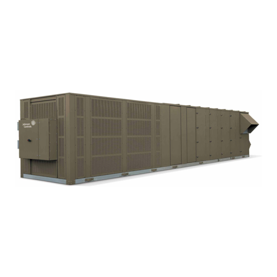
These compressors are manifolded to- ergy efficiency. All motors used on the Packaged Roof- gether in three independent circuits. top air conditioner meet U.S. EPACT 1992 minimum requirements. 00406vip FIGURE 1 - PACKAGED ROOFTOP AIR CONDITIONING UNIT JOHNSON CONTROLS... -
Page 14: Compressor Circuiting
The raised access floor concept is a proven design ideal louvered panel provides protection around the entire for office buildings that house today’s modern business condensing section giving the maximum protection to that relies on critical information technologies to main- the coils and refrigerant components. JOHNSON CONTROLS... -
Page 15: Controls
Solid wall liners encase insulation plications such as theaters and downtown areas. Con- and prevent moisture from damage. Additional benefits tact Johnson Controls for more details on site-specific include easy cleanability and isolates insulation from requirements. conditioned airstream. -
Page 16: Electrical
This option is available to minimize time at installation of equipment and to reduce necessary field installed This option provides a means to remove moisture, dirt items. and debris from the refrigeration circuit in the event it is opened. JOHNSON CONTROLS... -
Page 17: Section 2 - Installation
Not suitable for use with conventional venting systems. To ensure warranty coverage, this equip- ment must be commissioned and serviced LIMITATIONS by an authorized Johnson Controls service mechanic or a qualified service person The installation of this unit must conform to local experienced in packaged rooftop instal- building codes, or in the absence of local codes, with lation. -
Page 18: Rigging And Handling
Contact your Johnson Controls Sales Office if the unit. Also, the supply fan motor may you have any questions regarding unit weights. -
Page 19: Figure 4 - Lifting Lug Locations
9151 470.4 11949 EXTENDED 22.8 117.6 2981 181.9 4591 239.4 6172 307.0 7798 360.3 9151 470.4 11949 EXTENDED 22.8 117.6 2981 181.9 4591 239.4 6172 307.0 7798 360.3 9151 470.4 11949 LD18266 FIGURE 4 - LIFTING LUG LOCATIONS JOHNSON CONTROLS... -
Page 20: Table 3 - Physical Data
Compressor Data Motor Size Range (min. to max. HP) 10–20 Quantity/Size (Nominal HP) 6x10 Air Flow Range (min. to max. CFM) 4000–32000 Type Scroll Static Pressure Range (min. to max. ESP) 0–2” Capacity Steps (Qty x %) 6x16 JOHNSON CONTROLS... - Page 21 The diffuser is required in the ex- 16x20 / Size (length x width) (in.) tended cabinet for any unit with hot water or final filter option. 25x16 / 25x20 Total Filter Face Area (square feet) 55.8 JOHNSON CONTROLS...
- Page 22 Condenser Wire Guard Copper Condenser Coils (additional) 1,058 1,190 1,190 Copper Evaporator Coils (additional) Hot water coil Steam heating coil Diffuser Final filters Final filters, racks only Roof Curb Weights (Lbs.) 14” Full Perimeter Roof Curb 1,020 1,020 1,040 1,040 JOHNSON CONTROLS...
- Page 23 Static Pressure Range (min. to max. ESP) 1–8” 1–8” 1–8” 1–8” Exhaust Fan Quantity Type Size 18-18 18-18 18-18 18-18 Motor Size Range (min. to max. HP) 10–20 10–20 10–20 10–20 Air Flow Range (min. to max. cfm) 40000-32000 40000-32000 40000-32000 40000-32000 JOHNSON CONTROLS...
- Page 24 10 / 15 10 / 15 12 / 18 12 / 18 Size (length x width) (in.) 25x16 / 25x20 25x16 / 25x20 25x16 / 25x20 25x16 / 25x20 Total Filter Face Area (square feet) 77.1 77.1 92.5 92.5 JOHNSON CONTROLS...
- Page 25 1. Electric heat steps and airflow range depends on voltage and size. Consult the air pressure drop tables for specific number of steps for a given voltage. 2. Weights are for components only and need to be added to the extended cabinet weights. The diffuser is required in the extended cabinet for any unit with hot water or final filter option. JOHNSON CONTROLS...
-
Page 26: Electrical Data
58.0 45.0 144.0 136.0 68.0 56.0 149.0 135.0 67.8 54.4 TABLE 5 - CONDENSER FAN MOTOR DATA MODEL QUANTITY OF FANS 208V/3PH/60HZ 230V/3PH/60HZ 460V/3PH/60HZ 575V/3PH/60HZ YPAL070–105 43.8 37.2 18.6 15.0 NOTE: RLA data is per condenser fan motor. JOHNSON CONTROLS... -
Page 27: Table 6 - Miscellaneous Electrical Data
Entering Dry Bulb Temp (°F) (min/max) 68/90 68/90 68/90 68/90 68/90 Ambient Temp (°F) without Low Amb option 50/120 50/120 50/120 50/120 50/120 Ambient Temp (°F) with Low Amb option 0/120 0/120 0/120 0/120 0/120 *NOTE: Cooling only units JOHNSON CONTROLS... -
Page 28: Filters
3. Rotate the hoods out (each hood is hinged). Secure started. the hoods with screws along the top and sides. 4. Seal any unused screw holes with RTV or by re- placing the screw. JOHNSON CONTROLS... -
Page 29: Air Hoods For Fixed Outside Air (Units Without Economizer)
BAS system, or a manual Refer to Smoke Purge section on page 112 for addi- tional programming information. The smoke purge op- switch. erating state is maintained until the contact is opened. JOHNSON CONTROLS... -
Page 30: Vav Heat Relay Output
When the unit experiences rator coil. Johnson Controls does have a special curb a Supply Fan Fault, the IPU board closes a set of dry with the return duct bypass built into the curb. -
Page 31: Figure 7 - Field Control Wiring - Inputs
When the sensor uses 24VAC, additional wires must be run to terminal 1 (24VAC) and terminal 2 (24VAC COM) of the CTB1 terminal block. When the sensor requires a different power source than 24VAC, it must be field supplied. FIGURE 7 - FIELD CONTROL WIRING - INPUTS JOHNSON CONTROLS... -
Page 32: Figure 8 - Field Control Wiring - Outputs
2. All wiring is Class 2, low voltage. 3. Maximum power available from the 24VAC terminal is 40VA. 4. Use shielded wire where shown. 5. Relay contacts suitable for pilot duty to 1A from 24VAC to 120VAC. FIGURE 8 - FIELD CONTROL WIRING - OUTPUTS JOHNSON CONTROLS... -
Page 33: Electrical Service Sizing
TB2 in the power panel supplies power to the unit supply, return and exhaust fans, and control circuitry. All wiring must conform to the National Electrical Code (NEC) and local codes that may be in addition to NEC. JOHNSON CONTROLS... - Page 34 6. On units with an optional disconnect switch, the supplied disconnect switch is a “Disconnecting Means” as defined in the N.E.C. Section 100, and is intended for isolating the unit from the available power supply to perform maintenance and troubleshooting. This disconnect switch is not intended to be a Load Break Device. FIGURE 9 - SINGLE-POINT POWER SUPPLY WIRING JOHNSON CONTROLS...
-
Page 35: Figure 9 - Single-Point Power Supply Wiring
100, and is intended for isolating the unit from the available power supply to perform maintenance and troubleshooting. This disconnect switch is not intended to be a Load Break Device. FIGURE 10 - SINGLE-POINT POWER SUPPLY WIRING WITH NON-FUSED DISCONNECT JOHNSON CONTROLS... -
Page 36: Figure 11 - Dual-Point Power Supply Wiring
6. On units with an optional disconnect switch, the supplied disconnect switch is a “Disconnecting Means” as defined in the N.E.C. Section 100, and is intended for isolating the unit from the available power supply to perform maintenance and troubleshooting. This disconnect switch is not intended to be a Load Break Device. FIGURE 11 - DUAL-POINT POWER SUPPLY WIRING JOHNSON CONTROLS... -
Page 37: Transducer Pneumatic Tubing
(see Figure roof curbs are available upon request. 12 on page 38). Wood or fiber cant strips, roofing felts, roofing material, caulking and curb-to- roof fasteners are to be field supplied. JOHNSON CONTROLS... -
Page 38: Duct System
These losses must be taken into account during the design phase and must be added to any field measurements. Static Pressure Probe VIEW A-A LD06758A FIGURE 12 - STATIC PRESSURE PROBE LOCATION JOHNSON CONTROLS... -
Page 39: Gas Heating
NEVER USE A FLAME! 6. The furnace and its individual manual shut-off valve must be disconnected from the gas supply piping system during any pressure testing of that system at test pressures in excess of 0.5 PSIG. JOHNSON CONTROLS... -
Page 40: Combustion Vent
2. 4. See Figure 14 on page 40 for the proper orienta- tion of the combustion vent. The internal baffle(s) must direct the flue gases upward. FIGURE 14 - COMBUSTION VENT JOHNSON CONTROLS... -
Page 41: Section 3 - Start-Up
To protect warranty, this equipment must CHECKING THE SYSTEM PRIOR TO INITIAL be installed and serviced by an authorized START (NO POWER) Johnson Controls service mechanic or a Unit Checks qualified service person experienced in air handling and condenser unit instal- 1. -
Page 42: Figure 15 - Fan Isolator Spring Bolts (Total Of 8)
Figure 15. The bolt heads are red in water prior to unit start-up. color and a label identifies their location in the unit. SUPPLY FAN ASSEMBLY EXHAUST FAN ASSEMBLY RETURN FAN ASSEMBLY LD11448 FIGURE 15 - FAN ISOLATOR SPRING BOLTS (TOTAL OF 8) JOHNSON CONTROLS... -
Page 43: Unit Checks - Power Applied
ON, the compressor is properly phased and operating in the correct rotation. d. Connect a gauge manifold set to the Schrader service valve connections on the liquid and common suction line in the condensing sec- tion of the unit. JOHNSON CONTROLS... -
Page 44: Refrigerant Charge
Table 11 on page 45, for the corresponding discharge pressure. The superheat setting should be adjusted to 12.0°F at design conditions. JOHNSON CONTROLS... -
Page 45: Table 11 - R-410A Pressure Temperature Chart
FORM 100.50-NOM12 SECTION 3 – START-UP ISSUE DATE: 04/02/2019 TABLE 11 - R-410A PRESSURE TEMPERATURE CHART PSIG TEMP °F PSIG TEMP °F JOHNSON CONTROLS... -
Page 46: Leak Checking
Reconnect wires correctly. • If you cannot reach your gas supplier, call the • Verify proper operation after servicing. fire department. Installation and service must be performed by a quali- fied installer, service agency, or the gas supplier. JOHNSON CONTROLS... -
Page 47: Pre-Start Checks
7 second trial for ignition the control will turn off the spark signal, close the gas valve, wait 30 seconds and initiate a third ignition sequence. If flame rectification is not proven on the third try, the ignition control will lock out. JOHNSON CONTROLS... -
Page 48: Post Start Checks
• Correct manifold gas pressures. See Manifold Gas MAXITROL VALVE Pressure Adjustment on page 49. LO FIRE +/- HI FIRE+/- 0.3" W.C. 0.3" W.C. NATURAL 4.5" W.C. 10.5" W.C. 1.4" W.C. 3.5" W.C. PROPANE 11.0" W.C. 13.0" W.C. 4.2" W.C. 10.0" W.C. JOHNSON CONTROLS... -
Page 49: Manifold Pressure - Modulating Gas
12. Turn the heat OFF. REGULATOR 13. Turn the gas OFF. 14. Remove the brass tubing adapter and replace the TWO STAGE plug in the outlet pressure tap. PRESSURE REGULATOR INLET LD11760A FIGURE 16 - MANIFOLD GAS PRESSURE ADJUSTMENT JOHNSON CONTROLS... -
Page 50: Table 16 - Gas Heat Performance Data
GAS INPUT CAPACITY MAXIMUM OUTPUT CAPACITY UNIT TEMP. RISE (°F) (BTU/HR X 1000) (BTU/HR X 1000) MIN. MAX. 6,950 27,750 10-40 70-85 11,150 27,750 20-50 1125 15,150 33,325 25-55 6,950 27,750 10-40 90-105 11,150 27,750 20-50 1125 15,150 33,325 25-55 JOHNSON CONTROLS... -
Page 51: Section 4 - Maintenance
Never use the scroll compressor to pump due to improper maintenance during the warranty peri- the refrigerant system down into a vacu- od, Johnson Controls will not be liable for costs incurred um. Doing so will cause internal arcing to return the unit to satisfactory operation. -
Page 52: Recommended Lubricant For Fan Bearings
Bearings must be re-lubricated periodically to assure long life. Motor bearing should be lubricated yearly, but may need lubrication more frequently, depending on severe operating conditions. Cord Touching Sheaves At Points Indicated By Arrows LD07634 FIGURE 17 - SHEAVE ALIGNMENT JOHNSON CONTROLS... -
Page 53: Belts
Never close the suction line ball valve with the compressor running. Doing so will cause the compressor to pump-down into a vacuum and damage the compressor due to internal arcing. 00494vip FIGURE 18 - FAN DATA PLATE - BELT TENSION JOHNSON CONTROLS... -
Page 54: Forward Curved Fans
Series were removed or replaced, be sure to reuse any 100 Start-Up Checklist (Form 100.50-CL2). shim stock found between the mounting support/ plate and bearing housings. 11. Torque all hardware. JOHNSON CONTROLS... -
Page 55: Fan Shaft Bearings
FIGURE 21 - BEARING WITH SETSCREW TYPE material placed in the bearing. LOCKING DEVICE Prior to installing the bearing on the shaft, it should be worked around in the housing to make sure that self- alignment is obtained where the bearing is installed. JOHNSON CONTROLS... -
Page 56: Eccentric Type
Table 18 on page 57. It exerts a wedging action to hold the collar always in the engaged position, even under shock and reversing loads. To disassemble, loosen the setscrew and tap the collar in the direction opposite shaft rotation. JOHNSON CONTROLS... -
Page 57: Torquing Of Set-Screws
After proper installation of the bearing(s), Sleeve run the unit for 10 to 15 minutes. Shut the unit down and lock it out. Check for proper engagement of locking collar and tightness of set screw(s). Seal 00536vip FIGURE 24 - SPLIT BEARING JOHNSON CONTROLS... - Page 58 FORM 100.50-NOM12 ISSUE DATE: 04/02/2019 THIS PAGE INTENTIONALLY LEFT BLANK JOHNSON CONTROLS...
-
Page 59: Section 5 - Sequence Of Operation
• A SZVAV configured unit has a supply fan, con- trolled by a VFD that is capable of running at dif- ferent speeds according to a cooling/heating de- LD28114 FIGURE 25 - UNIT OPTIONS mand or supply fan only demand. JOHNSON CONTROLS... -
Page 60: Flexsys
1. The control switch, SD terminal, and phase monitor are wired in series and provide 24 VAC to the I/O board. The SD terminal on CTB1 is where a remote shutdown device can be connected. A jumper is installed between 24 VAC and SD terminal from the factory. JOHNSON CONTROLS... -
Page 61: Occupancy/Unoccupancy Determination
• Night set-back must be User Enabled in the PRO- GRAM-UNIT DATA menu (on older software versions, night set-back was located in the PRO- GRAM-HEATING menu and could only be User Enabled if the Series 100 unit had a heating source installed). JOHNSON CONTROLS... -
Page 62: Single Zone Vav (Szvav)
Wired or Comm Zone Temperature). • SZVAV units can be controlled by either a stan- • 1st and 2nd stage cooling setpoints must be set in dard thermostat (staged) input or a zone tempera- the SETPOINTS-COOLING menu. ture input. JOHNSON CONTROLS... -
Page 63: Supply Fan
Occ Heating Low Occ Heating High Supply fan speed at 100% Unocc Heating Low Unocc Heating High Comfort Vent Cool Comfort Vent Heat Morning Warm-Up Occ Standby (continuous ventilation is User Disabled) Supply fan is OFF Unocc Standby JOHNSON CONTROLS... -
Page 64: Cooling And Heating Operation
• These SPs are also available on a BAS. a. Wired zone temperature • Table 23 on page 66 shows the active SAT set- points for each unit mode in SZVAV. b. Communicated zone temperature 2. Staged input a. Thermostat (2 stage cooling/heating) b. BAS commands JOHNSON CONTROLS... -
Page 65: Table 22 - Szvav - Current Unit Modes
1. When a SZVAV unit is being controlled by a staged input, a demand for Y2 terminal causes the supply fan to go directly to 100% from SZVAV minimum speed. There is no modulation as with zone temperature. JOHNSON CONTROLS... -
Page 66: Variable Air Volume (Vav)
• The VFD speed is controlled by a duct static pres- must be set in the SETPOINTS-COOLING menu. sure transducer that also provides high duct static • SAT low and high setpoints must be set in the pressure protection. SETPOINTS-COOLING menu. JOHNSON CONTROLS... -
Page 67: Supply Fan
BAS, BACnet MS/TP point AV05. Duct tory installed tube that passes through the supply pressure reset BAS must be User Enabled. fan wall into the next section of the unit. Duct pressure reset BAS can be found in the SERVICE menu. JOHNSON CONTROLS... -
Page 68: Figure 27 - Active Duct Static Pressure Setpoint Vs. Duct Static Pressure Reset Voltage
• When the VDC signal drops to approximately 0.5 • Supply fan sync is only applicable for Series 100 VDC, the supply fan shuts down on auto reset. units configured as VAV. After voltage increases above 1 VDC, the supply fan restarts. JOHNSON CONTROLS... -
Page 69: Cooling And Heating Operation
RAT setpoint by 0.5°F 5 VDC 100% at approximately 60hz Unocc Standby No demand for cooling or heating exists Johnson Controls recommends installing Current zone temperature is above the the tubing from the duct static pressure Unocc Cooling unocc cooling zone setpoint by 0.5°F... -
Page 70: Figure 28 - Active Sat Setpoint Versus Sat Reset Voltage
SAT causes the active cooling SAT setpoint to be between the high SAT and low • The IPU board monitors the current RAT and SAT setpoints. See Figure 30 on page 71. reset the active SAT setpoint as needed. JOHNSON CONTROLS... -
Page 71: Figure 29 - Active Sat Setpoint Versus Rat
(Default = 65.0 Active SAT Setpoint SAT LOW SETPOINT (Default = 55.0 °F) OAT SETPOINT Outside Air Temp OAT SETPOINT FOR HIGH SAT FOR LOW SAT (OAT) Increasing OAT LD12588 FIGURE 30 - ACTIVE SAT SETPOINT VERSUS OAT JOHNSON CONTROLS... -
Page 72: Figure 31 - Active Sat Setpoint Versus Supply Fan Speed
FAN SPEED FAN SPEED Supply Fan Speed FOR LOW SAT FOR HIGH SAT Increasing Supply Fan Speed LD10308A FIGURE 31 - ACTIVE SAT SETPOINT VERSUS SUPPLY FAN SPEED LD28116 FIGURE 32 - VARIABLE AIR VOLUME (VAV) — OCCUPIED JOHNSON CONTROLS... -
Page 73: Compressors: Control And Operation
ON/OFF to achieve ent package. and maintain the active cooling SAT setpoint. • See Table 27 on page 74 for compressor stag- • Under normal operation, each compressor has a ing. 3.5 minute guaranteed ON/OFF timer. JOHNSON CONTROLS... -
Page 74: Fast Compressor Start
4. One of the variables used in fast compressor start is the unit design airflow. This value needs to be entered correctly for fast compressor start to work properly. Unit design airflow can be found in the SETPOINTS-UNIT DATA menu. JOHNSON CONTROLS... -
Page 75: Compressor Status
60 minute timer where the fault needs • Table 29 shows the different messages that can be to clear. If the fault does not clear within 60 min- displayed. utes, a Lockout-Comp System Timeout displays. JOHNSON CONTROLS... -
Page 76: Figure 34 - Compressor Safety Chain - Without Compressor Protection Module
IPU board. pressor safety circuit. • When any of the safety switches open, compres- sor operation terminates immediately, and a com- pressor safety trip occurs. LD28118 FIGURE 34 - COMPRESSOR SAFETY CHAIN — WITHOUT COMPRESSOR PROTECTION MODULE JOHNSON CONTROLS... -
Page 77: Figure 35 - Compressor Safety Chain - With Compressor Protection Module
SECTION 5 – SEQUENCE OF OPERATION ISSUE DATE: 04/02/2019 LD28119 FIGURE 35 - COMPRESSOR SAFETY CHAIN — WITH COMPRESSOR PROTECTION MODULE LD28120 FIGURE 36 - COMPRESSOR SYSTEM STATUS INPUT TO I/O BOARD LD28121 FIGURE 37 - LOW PRESSURE CUTOUT (LPCO) SWITCH WIRING JOHNSON CONTROLS... -
Page 78: Resetting A Compressor System Safety Lockout
• The compressor remains off until the suction line temperature rises above the suction temperature low limit by 10.0°F for 10 minutes. JOHNSON CONTROLS... -
Page 79: High Discharge Pressure Unloading
2 • The mechanical cooling lockout temperature is • When HGRH is active, the number of available user adjustable on a compressor system with a low cooling stages is reduced ambient package installed. JOHNSON CONTROLS... -
Page 80: Figure 38 - Hgrh 3-Way Stepper Valve
7 Flashes 60–70% 8 Flashes 70–80% 9 Flashes 80–90% 10 Flashes 90–99% Remains Lit 100% OUTLET B: TO HGRH COIL FROM DISCHARGE LINE CKT 2 OUTLET A: TO CONDENSER COIL LD20876 FIGURE 38 - HGRH 3-WAY STEPPER VALVE JOHNSON CONTROLS... -
Page 81: Figure 39 - Hgrh Control Board
TABLE 32 - NUMBER OF STEPS 6386 3196 2500 1596 TABLE 33 - VALVE TYPE Bipolar Unipolar Std Direction Reverse Std Response Quick 200pps 400pps Std Operation Close Valve LD20878 and LD20879 FIGURE 39 - HGRH CONTROL BOARD JOHNSON CONTROLS... -
Page 82: Hgrh Setup
• Dehumidification control must be set to User En- • Dehumidification is not required abled under PROGRAM-UNIT DATA menu. • No Active HGRH Faults exist • Units with HGRH have a combination RAT and return air humidity sensor installed. JOHNSON CONTROLS... -
Page 83: Hgrh Sequence Of Operation
• The active HGRH SAT setpoint is a calculated delay the HGRH bleed solenoid opens. value between the HGRH SAT high and low set- points based on the current RAT and the HGRH RAT high and low setpoints. (Figure 42) JOHNSON CONTROLS... -
Page 84: Hgrh Faults
• HGRH valve position is greater than 50% • The current SAT is 8.0°F less than the current evaporator air temperature LD28122 FIGURE 43 - CONDENSER FAN CONTACTORS — FANS 1A AND 1B ONLY FOR COMPRESSOR SYSTEM #1 JOHNSON CONTROLS... -
Page 85: Low Ambient Kit
• The unit must be in an Active Cooling mode for • The IPU board modulates the outside air damper the economizer to become active. to try to achieve and maintain the active cooling SAT setpoint. JOHNSON CONTROLS... -
Page 86: Heating
• The heating capacity determines the number of becomes invalid, the economizer method used furnaces installed. switches to a different method. • Each furnace has a 2 stage gas valve, an ignition control module, and an induced draft fan motor. JOHNSON CONTROLS... -
Page 87: Figure 45 - Digital Multiplexor Connections For Staged Gas Heat
Ignition control did not prove flame, or other FAULT flame is not established by the third try, the igni- safety switch opened tion control locks out for 1 hour. FAULT- Multiplexor output to I/O board is not LOCKOUT accurate JOHNSON CONTROLS... -
Page 88: Modulating Natural/Propane Gas Heat
1. When Multiplexor output to I/O board is not FAULT-LOCKOUT accurate either 1A or 1B is in a fault, both halves are not al- lowed to operate. Furnace sections 2 and 3 are still allowed to operate. JOHNSON CONTROLS... -
Page 89: Figure 46 - Modulating Gas Furnace Sections
This lets the ignition control know • After 15 seconds of steady flame rectification, the that all safety switches are closed. ignition control: • There is a 30 Second Purge Timer that allows the inducer motor to flush the furnace with clean air. JOHNSON CONTROLS... -
Page 90: Figure 47 - Digital Multiplexor Connections For Modulating Gas Heat
• The inducer motor switches to high speed. • When the heating demand increases, the 0–10 VDC signal increases, which further opens the modulating valve. • When the heating demand decreases, the 0–10 VDC signal decreases, which closes the modulating gas valve. JOHNSON CONTROLS... -
Page 91: Figure 48 - Modulating Gas Heat Staging Sequence
3 sequence as long as the fire. heating demand keeps increasing. • Furnace 1A starts at low fire min and goes through the low fire to high fire se- quence as described above. LD10151 FIGURE 48 - MODULATING GAS HEAT STAGING SEQUENCE JOHNSON CONTROLS... -
Page 92: Figure 49 - Digital Multiplexor Control Board
• TB1-3: 24 VAC input from furnace 2, • TB1-7: 24 VAC common from T5 trans- DS3 is lit (750 MBH heating capacity) former • TB1-4: 24 VAC input from furnace 3, DS4 is lit (1125 MBH heating capacity) JOHNSON CONTROLS... -
Page 93: Table 36 - Staged Gas Heat 0-5 Vdc Outputs To Ipu
0.499 0.609 0.637 0.756 0.774 0.904 0.912 1051 1.050 1.199 1.187 1.346 1.325 1.494 1.463 1.641 1.600 1.789 1.738 1.936 1.876 2.084 2.013 2.231 2.151 2.379 2.289 2.526 2.426 2.674 2.564 2.821 2.702 2.969 2.839 3.116 2.977 3.264 JOHNSON CONTROLS... -
Page 94: Electric Heat
1. A 750 MBH capacity is used with furnace sections 1 and 2. A 1125 MBH ca- • Ensure that Heating System is User Enabled un- pacity is used with furnace sections 1, 2, and 3. der the PROGRAM-HEATING menu. JOHNSON CONTROLS... -
Page 95: Hot Water/Steam Heat
SAT setpoint. impact the hot water/steam operation. • The IPU board monitors the status of the factory • The hot water/steam valve is field provided/in- installed freezestat to prevent coil freezing of the stalled. hot water/steam coil. JOHNSON CONTROLS... -
Page 96: Heating Sequences
1. VAV or FlexSys: SAT heating es associated with the different heating options. 2. SZVAV: 2nd stage heating • Each of these sequences can be User Enabled/User Disabled in the PROGRAM-HEATING menu. • They can also be User Enabled/User Disabled through a BAS. JOHNSON CONTROLS... - Page 97 [day 1], [day 2], [day 3] shall be initially set to 60 minutes. • The Series 100 unit enters an Occ mode These values can be reset to the default val- ues by turning morning warm-up to User Dis- abled, then back to User Enabled. JOHNSON CONTROLS...
-
Page 98: Supply Air Tempering
• Supply air tempering becomes INACTIVE cooling SAT setpoint (mixed SAT setpoint when the current heat entering temperature for FlexSys). becomes greater than the active cooling SAT setpoint for 5 minutes. • Supply air tempering becomes INACTIVE when the following conditions are satisfied: JOHNSON CONTROLS... -
Page 99: Ventilation
• The unit was ordered with optional CO sen- damper is determined by the ventilation demand. sors. • Outside air damper minimum and maximum posi- tions must be set in the SETPOINTS-VENTILA- TION menu. JOHNSON CONTROLS... -
Page 100: Tek-Air Full Iaq
CFM. 3. Ventilation demand between 0 and 100%: outside air damper between minimum and • The Tek-Air can be set-up for either fixed mini- maximum positions mum or demand ventilation control. JOHNSON CONTROLS... -
Page 101: Figure 52 - Tek-Air Full Iaq With Demand Ventilation
OPTIONS-VENTILATION menu. • Control type must be set to Demand in the PRO- GRAM-VENTILATION menu. • CO sensors must be set to Installed in the OP- LD28129 TIONS-VENTILATION menu. FIGURE 52 - TEK-AIR FULL IAQ WITH DEMAND VENTILATION JOHNSON CONTROLS... -
Page 102: Continuous Ventilation
• When the current SAT becomes less than the occ LD28130 zone cooling setpoint by 5.0°F for 5 minutes, the FIGURE 53 - EXHAUST FAN ASSEMBLY IPU board stops comfort ventilation cool. JOHNSON CONTROLS... -
Page 103: Exhaust Fan Assembly
• The exhaust fan assembly can be ordered as one offset, the exhaust fan is turned ON. of four options. JOHNSON CONTROLS... - Page 104 • Power exhaust type must be set to Modulate Damp- SETPOINTS-EXHAUST menu. er - VFD in the OPTIONS-EXHAUST menu. • This sequence uses a modulating exhaust damper • Exhaust control BAS must be User Enabled in the with a single speed exhaust fan. SERVICE menu. JOHNSON CONTROLS...
-
Page 105: Return Fan Assembly
• The IPU board monitors the return fan plenum pres- sure and controls the speed of the return fan VFD up/down to maintain the return fan plenum pressure LD28131 setpoint. FIGURE 55 - ACTIVE RETURN PLENUM PRESSURE SETPOINT VERSUS EXHAUST OUTPUT JOHNSON CONTROLS... -
Page 106: Flexsys
• The FlexSys configuration allows the Series 100 unit to operate in a manner that best suits an un- • Johnson Controls engineers have found during derfloor HVAC system. extensive testing that RATs cooler than 78.0°F cannot properly raise the temperature of the air •... -
Page 107: Flexsys Setup
• In the Unocc mode, the IPU compares the unocc zone cooling and unocc zone heating setpoints against the current zone temperature to determine if there is a demand for cooling or heating. LD28132 FIGURE 56 - FLEXSYS — OCCUPIED JOHNSON CONTROLS... -
Page 108: Fan Operation
Occ Cooling without By- • The IPU board has internal logic it uses to deter- pass mode. mine which Occ Cooling mode to use. • When in Occ Cooling without Bypass, the re- turn air bypass damper remains fully closed. JOHNSON CONTROLS... - Page 109 SAT setpoint. more than 40% of the total return air. • When the current RAT is greater than the • Johnson Controls offers a specially designed active RAT setpoint plus 0.5°F and the cur- curb for FlexSys configured units that incor- rent RAT greater than the current mixed SAT porate the return air bypass duct and damper.
-
Page 110: Heating
EAT high setpoint to the EAT low in the PROGRAM-COOLING menu. setpoint when the temperature of the underfloor air approaches its dewpoint. • The unit must have an underfloor slab temperature sensor installed for this sequence to function. JOHNSON CONTROLS... -
Page 111: Figure 58 - Ctb1 Field Control Wiring Inputs
SAT + (SUPPLY AIR TEMP RESET +) LD08184D FIGURE 58 - CTB1 FIELD CONTROL WIRING INPUTS SAT - (SUPPLY AIR TEMP RESET -) +5V (DUCT STATIC SP + 5V) Duct Pressure Setpoint Reset DSP+ (DUCT STATIC RESET +) JOHNSON CONTROLS DSP- (DUCT STATIC RESET -) -
Page 112: Smoke Purge
2. Start the return fan (if applicable). 3. Start the exhaust fan (if applicable). 4. Close outside air dampers to 0% (if applicable). 5. Open return air dampers to 100% (if applicable). 6. Open the exhaust dampers to 100% (if applicable). JOHNSON CONTROLS... -
Page 113: Section 6 - User Interface Control Center
STATUS SETPOINTS UNIT DATA PROGRAM COOLING OPTIONS COMPRESSOR SYSTEMS DATE/TIME SUPPLY SYSTEM SCHEDULE OPERATING HOURS HEATING START COUNTER ECONOMIZER PRINT VENTILATION SERVICE EXHAUST HISTORY UNIT LD010669 FIGURE 59 - USER INTERFACE CONTROL PANEL JOHNSON CONTROLS... -
Page 114: Navigation Keys
OPTIONS) to use to change the value (if applicable), achieved by repeated presses of the same Menu Select and under what circumstances the item is displayed. key, as long as no other keys are pressed. For example, pressing the UNIT DATA key three times will bring JOHNSON CONTROLS... -
Page 115: Table 41 - Status
Derived Always STATUS Safety Fault / Safety Lockout / User Disabled / None SENSOR / MISC Normal / Warning / Safety Trip / Safety Fault / Derived Always STATUS Safety Lockout FILTER STATUS Okay / Change Derived Always JOHNSON CONTROLS... -
Page 116: Table 42 - Unit Data
Evacuation Always SEQ 3 Evacuation Unit Data Options / DISPLAY LANGUAGE English / Spanish English Always Unit Data DISPLAY UNITS Imperial / Metric Imperial Always * Only the zone temp screen for the current active mode is shown. JOHNSON CONTROLS... -
Page 117: Table 43 - Cooling
30.0°F To 100.0°F Derived Setpoints/ MAXIMUM BYPASS 20–40% Unit type equals FLEXSYS Cooling User Enabled User Program/ DEW POINT RESET User Disabled Unit type equals FLEXSYS Disabled Cooling UNDER FLR TEMP Active - Inactive Derived Unit type equals FLEXSYS OVRD JOHNSON CONTROLS... - Page 118 Ambient Pkg Other Than None MECH CLG LOCKOUT Setpoints/ Press Trans Pkg And Low -10.0°F To 0.0°F 0.0°F TMP MINIMUM Cooling Ambient Pkg Other Than None * Only the zone temp screen for the current active mode is shown. JOHNSON CONTROLS...
-
Page 119: Table 44 - Compressor Systems (1, 2, Or 3)
PRESS TRANS PKG None Always Sys 1, 2, 3 Comp Sys None / Sys 1 / Sys 1, 2 / Optional/ LOW AMBIENT PKG None Always Sys 1, 2, 3 Comp Sys * May be 1, 2, or 3 JOHNSON CONTROLS... -
Page 120: Table 45 - Supply System
DUCT STATIC OVER Setpoints / Unit Type Equals Variable Air 0 - I iwg - 5 In-Wg 3.0 In-Wg PRESSURE Supply System Volum Or FLEXSYS RETURN Setpoints / Power Exhaust Equals Return PRESSURE HIGH 0.15–0.45 0.15 Supply System W/Exhaust SETP JOHNSON CONTROLS... -
Page 121: Table 46 - Heating
Setpoint -2.0°F HEAT ENTERING Look Up -20.0°F To 180.0°F Heat Type Equals Staged Gas TEMP Table STAGED HEAT STATUS STGS ON 0 To 6 Derived Heat Type Equals Electric Or Staged Gas STGS AVAL 2 To 6 Derived JOHNSON CONTROLS... - Page 122 Heat Type Does Not Equal HEATING SYSTEM Program / Heating Disabled Enabled None Heat Type Does Not Equal User Enabled User User None And Constant Volume MORNING WARM UP Program / Heating Disabled Disabled Control Method Does Not Equal Staged JOHNSON CONTROLS...
- Page 123 Warm Up Max Time Equals Enabled Heat Type Does Not Equal MORNING WARM UP 15–240 Min. 120 Min. Setpoints/Heating None And Morn Warm Up MAX TIME Equals Enabled * Only the zone temp screen for the current active mode is shown. JOHNSON CONTROLS...
-
Page 124: Table 47 - Economizer
Look Up Table Dual Enthalpy OUTSIDE AIR Economizer Installed Does ENTHALPY 22.0–40.0 BTU/LB 28.0 BTU/LB Setpoints / Economizer Not Equal None SETPOINT ECONOMIZER User Enabled User Economizer Installed Does Disabled Program / Economizer SYSTEM Disabled Not Equal None JOHNSON CONTROLS... -
Page 125: Table 48 - Ventilation
Damper Hardware Tek-Air And Derived Span Setpoints / OA FLOW 0–100% Ventilation Control Set To Fixed X 15% Ventilation SETPOINT Minimum VENTILATION User Enabled User Program / Damper Hardware Does Not Equal User Enabled SYSTEM Disabled Ventilation None JOHNSON CONTROLS... -
Page 126: Table 49 - Exhaust
Setpoints / Power Exhaust Equals FOR FAN START Stop To 100% Exhaust Modulate Damper - VFD EXHAUST OUTPUT 0 To Exhaust Output For Setpoints / Power Exhaust Equals FOR FAN STOP Fan Start Exhaust Modulate Damper - VFD JOHNSON CONTROLS... -
Page 127: Setpoints
126. Use the ▼ key and the ▲ key to navigate to the CLOCK FRI 18 JUN 2004 10:15:33 AM parameter to change. Follow the instructions given in MINUTE the section Data Entry Keys on page 113 to change the parameter to the desired value. JOHNSON CONTROLS... -
Page 128: Schedule
± key is used to delete the *. The START =06:00 AM STOP =10:00 PM key is used to accept the holiday schedule for the next seven days. SCHEDULE TO EDIT START =06:00 AM STOP =10:00 PM JOHNSON CONTROLS... -
Page 129: Operating Hours / Start Counter
Power Exhaust On/Off Dmpr / On/Off Derived EXHAUST FAN STARTS Press / Modulate Damper - VFD. SUPPLY FAN OPER HRS Derived SUPPLY FAN STARTS RETURN FAN OPER HRS Supply System Type Equals Return Fan Derived RETURN FAN STARTS W/Exh Return W/O Exhaust. JOHNSON CONTROLS... -
Page 130: Printer
• After the reports finish transferring to the PC, se- After selecting the report to print, press the key to lect Transfer – Capture to Printer to send the last output the report to the PC. page to the printer. JOHNSON CONTROLS... -
Page 131: Service
◄ key can be used to page 132 for a listing of the analog outputs jump to the beginning of the previous section of dis- plays. SERVICE AO PIO TB08-01 XX.X VDC + SYS 1 FEED VALVE OUTPUT =XXX.X % JOHNSON CONTROLS... -
Page 132: Table 51 - Service
Status Of Electric Heat Digital Output To ELECTRIC HEAT STG 6 TB3-8 On / Off I/O Board Output Stage 6 Digital Status Of Electric Heat Digital Output To ELECTRIC HEAT STG 7 TB3-9 On / Off I/O Board Output Stage 7 JOHNSON CONTROLS... - Page 133 Digital Output That Is Generated When SENSOR/MISC FAULT TB1-10 On / Off I/O Board Output There Is A Sensor/Misc Fault SUPPLY FAN VFD 0-10 Analog TB9-1 I/O Board Analog Output To The Supply Fan VFD SPEED Output Volt Dc JOHNSON CONTROLS...
- Page 134 Discharge Pressure Transducer PRESSURE Analog Analog Input From The System 3 J4-5 0-5 Volts I/O Board DISCHARGE 3 Input Discharge Pressure Transducer Analog Analog Input Of The Outdoor CO CO2 LEVEL OUTSIDE J5-2 0-5 Volts I/O Board Input Sensor JOHNSON CONTROLS...
- Page 135 Digital Furnace Furnace 2 Status Input To Furnace FURNACE 2 STATUS TB01-3 On / Off Input Multiplexer Multiplexer Board Digital Furnace Furnace 3 Status Input To Furnace FURNACE 3 STATUS TB01-4 On / Off Input Multiplexer Multiplexer Board JOHNSON CONTROLS...
- Page 136 Port P1 IPU Board User Enable Communicate A CO Value To The Unit The Inside CO Value Being CO2 LVL INSIDE VALUE 101 To 1899 Commun Port P1 IPU Board Communicated To The Unit Through The Bas System JOHNSON CONTROLS...
- Page 137 Commun Port P1 IPU Board Communicate A Under Floor Humidity User Enable Value To The Unit UNDRFLOOR AIR The Under Floor Humidity Value Being Commun Port P1 0 To 100% IPU Board HUMIDITY BAS Communicated To The Unit JOHNSON CONTROLS...
- Page 138 -1 To 127 The Mac Address For Port 1. See ADDRESS Communication section on page 142. None, Even, Do Not Change From Default Value For P1 PARITY Odd, Ignore BACnet P1 PROTOCOL BACnet, Api Keep Setting On BACnet JOHNSON CONTROLS...
- Page 139 Establishes The Protocol For P4 PROTOCOL Modbus Server, Communication Port 4 Api, Modbus Client Establishes The Stop Bit Setting For P4 STOP BITS 1 - 2 Communication Port 4 CONNEXSYS ERROR FEATURE AND Derived Not For Field Use DETECTION JOHNSON CONTROLS...
-
Page 140: History
After entering the Level 2 password, the most recent displayed in the same order and with the same message warning is displayed. used under the respective menu function: HISTORY WARNING ◄► • Status + WRN-BUILDING PRS • Unit Data • Cooling JOHNSON CONTROLS... -
Page 141: Password
Each level of access is associated with a specific password. The access levels available are Level 1 or sage displays for two seconds. The top line displays the copyright message. The bottom line displays the Level 2. software version and the present date and time. JOHNSON CONTROLS... -
Page 142: Connecting Bas To A Rooftop Unit With The Ipu Board
2 - Ground 3 - Receive (-) 4 - Transmit (+) 5 - Open PORT 1 (J4) PORT 4 (J3) PORT 2 (J5) NOT USED MAC ADDRESS SWITCH PORT 3 (J2) LD11197C FIGURE 60 - IPU CONTROL BOARD JOHNSON CONTROLS... -
Page 143: Device Object Instance (De)
(DE) be set to a given value. This can be done through the User Interface. To do this you would use PORT 4 the “DE MODIFIER ADDRESS” in conjunction with “P4 BAUD RATE” the “DE MODIFIER OFFSET.” Using this feature “P4 MANUAL MAC ADDRESS” JOHNSON CONTROLS... -
Page 144: Table 53 - Bacnet Ms/Tp, Modbus, Bacnet Ip
Displays The Status Of The Comfort Vent COMFORT_ Comfort Ventilation AV78 BV02 1103 Option And Allow It To Be Turned On/Off: VENT (Constant Volume) 0=Off 1=On Compressor 1A Displays The Status Of Comp 1A: 0=Off COMP_1A BI03 1284 Status 1=On JOHNSON CONTROLS... - Page 145 COND_FAN_1A BI15 1296 Status 0=Off 1=On Cond Fan 1B/2 Displays The Status Of Cond Fan 1B/2: COND_FAN_1B BI16 1297 Status 0=Off 1=On Cond Fan 2A/3 Displays The Status Of Cond Fan 2A/3: COND_FAN_2A BI17 1298 Status 0=Off 1=On JOHNSON CONTROLS...
- Page 146 4=Best Method Avail Displays The Active Sp For The High Evap Leaving Air EL_AIR_ Evap Leaving Air Temp. This Is The Sp Temp High Sp AV07 1032 TMP_H The Compressors Are Controlled To (OCC (FlexSys) Cooling W/ Bypass) JOHNSON CONTROLS...
- Page 147 Mod Gas Furn 2 1=On Low Status Elect Heat Stage 4 Status Staged Gas Displays The Status Of The Control Output FURN_OUT_4 Furn 2 High Status BI29 1310 To The Indicated Heat Section: 0=Off Mod Gas Furn 2 1=On High Status JOHNSON CONTROLS...
- Page 148 Mech Cooling Displays The Min OA Temp At Which Mech AV12 1037 Lockout Sp Cooling Is Allowed To Operate Outside Air Min Displays The Min Airflow For Demand MIN_FLOW_DV AV13 1038 Flow Sp Ventilation With An Airflow Station (CFM) JOHNSON CONTROLS...
- Page 149 Displays The Total Air Flow Through A Tek- OA Flow Total AI63 TOTL Air Full Iaq Air Measuring Station (CFM) OA_REL_ Displays The Current OA Relative OA Humidity AI29 HUMID Humidity (%) OA_TEMP OA Temperature AI30 Displays The Current OA Temp JOHNSON CONTROLS...
- Page 150 DOWN_2 Status Ckt 2 Liq Line Solenoid Vlv: (0=On 1=Off) Pump Down Llsv 3 PUMP_ Displays The Status Of The Output To The Status (70-150 Ton BI39 1320 DOWN_3 Ckt 3 Liq Line Solenoid Vlv: (0=On 1=Off) Only) JOHNSON CONTROLS...
- Page 151 Comp 3B Status BI51 1332 To Stop If Operating: (Yes/No) (70-150 Ton Only) Displays The Value (%) For The Current RET_AIR_ Return Air Bypass AI37 Sp Of The Ra Bypass Damper Onn A BY_S Active Sp FlexSys Unit JOHNSON CONTROLS...
- Page 152 For Switching To The High Supply Air Hi Supply Air Temp Temp Sp Displays The Supply Fan Speed Sp Used SF_SPD_L_ Fan Speed Sp For AV30 1055 For Switching To The Low Supply Air Temp Lo Supply Air Temp JOHNSON CONTROLS...
- Page 153 33% and 66% when Minimum VFD using SZVAV. Displays The Actual System 1 Suct Line TEMP_1_SUCT Suct Temp Ckt 1 AI49 Temp (°F) TEMP_1_ Suct Superheat AI50 Displays The System 1 Superheat (°F) SUPER Ckt 1 *Not Available JOHNSON CONTROLS...
- Page 154 8=OCC Standby 9=UNOCC Cool UNIT_MODE Current Oper Mode AI58 10=UNOCC Cool Low 11=UNOCC Cool High 12=UNOCC Heat 13=UNOCC Heat Low 14=UNOCC Heat High 15=UNOCC Standby 16=Comfort Vent Cool 17=Comfort Vent Heat 18=Night Set-Back 19=Morning Warm-Up 20=Power Up Standby JOHNSON CONTROLS...
- Page 155 NOTES 1. The most up to date listing of the Standard Points Mapping can be found on the Johnson Controls website 2. For a Building Automation System using BACnet IP, a gateway must be used, since the IPU board does not have a BACnet IP port. We...
- Page 156 FORM 100.50-NOM12 SECTION 6 – USER INTERFACE CONTROL CENTER ISSUE DATE: 04/02/2019 THIS PAGE INTENTIONALLY LEFT BLANK JOHNSON CONTROLS...
-
Page 157: Section 7 - Parameter Descriptions And Options
This parameter is programmed through the PROGRAM key. This is only used on a Constant CONTINUOUS VENT Volume unit. When this parameter is enabled the supply blower will operate whenever the unit is in the Occupied mode. The choices are USER ENABLED or USER DISABLED. JOHNSON CONTROLS... - Page 158 DUCT STATIC RESET This parameter is programmed through the SETPOINTS key. This is the maximum Duct Static HIGH SETP Control point. ECONOMIZER CONTROL This is the analog output from the IPU board to the Economizer Damper Actuator. OUTPUT JOHNSON CONTROLS...
- Page 159 This is the current status of the first heat exchanger section of a staged gas heat unit. The FURNACE 1 MODE User Interface will display Off, Purge, Ignition, On-Low, On-High, Safety Trip, Safety Fault, Safety Lockout, or Fault- I/O. JOHNSON CONTROLS...
- Page 160 This is the approximate firing rate of the modulating gas heat section in MBH. APRX RATE FURNACE 1A MODE This is the output from the IPU board to the modulating gas heat section in percent of full RELATIVE capacity. JOHNSON CONTROLS...
- Page 161 This is the discharge pressure and is shown for each compressor system if pressure DISCHARGE* transducers are installed and configured for the system. This is the suction pressure and is shown for each compressor system if pressure transducers PRESSURE SUCTION* are installed and configured for the system. JOHNSON CONTROLS...
- Page 162 SAFETY INPUT CHAIN circuit breaker. ON means the safety circuit is normal and FAULTED means it has faulted. This parameter is shown for each compressor system. JOHNSON CONTROLS...
- Page 163 IPU board PRESSURE will turn off one of the compressors. This feature is only operative when a discharge pressure transducer is installed in the compressor system. JOHNSON CONTROLS...
- Page 164 ZONE HEATING IPU board compares the actual space temperature to, to decide when to switch into the SETPOINT Unoccupied Heating Mode. ZONE TEMP CURRENT This is the temperature in the conditioned space. * May be 1, 2, or 3 JOHNSON CONTROLS...
-
Page 165: Section 8 - Service
35,639 -3.89 3.76 4,951 43.34 1.62 31,269 -1.11 3.85 4,475 46.11 1.77 27,490 1.67 3.94 4,050 48.89 1.91 24,219 4.44 4.02 3,671 51.66 2.06 21,377 7.22 4.09 3,332 54.44 2.21 18,900 10.00 4.16 3,029 57.22 2.36 16,744 12.78 JOHNSON CONTROLS... -
Page 166: Building Pressure Transducer
Table 57 on page 166. DIFFERENTIAL INPUT OUPTUT VOLTAGE - VDC PRESSURE - "W.C. -1.00 0.00 -0.80 0.50 -0.60 1.00 -0.40 1.50 -0.20 2.00 0.00 2.50 0.20 3.00 0.40 3.50 0.60 4.00 0.80 4.50 1.00 5.00 JOHNSON CONTROLS... -
Page 167: Discharge Pressure Transducer
RELATIVE VOLTAGE RELATIVE VOLTAGE 2.00 2.00 HUMIDITY HUMIDITY 2.50 2.50 0.25 2.75 3.00 3.00 0.50 3.00 3.50 3.50 0.75 3.25 4.00 4.00 1.00 3.50 4.50 4.50 1.25 3.75 1.50 4.00 1.75 4.25 2.00 4.50 2.25 4.75 2.50 5.00 JOHNSON CONTROLS... -
Page 168: Table 61 - Co Sensor Output
0.774 0.904 0.912 1.051 1.050 1.199 1.187 1.346 1.325 1.494 1.463 1.641 1.600 1.789 1.738 1.936 1.876 2.084 2.013 2.231 2.151 2.379 2.289 2.526 2.426 2.674 2.564 2.821 2.702 2.969 2.839 3.116 2.977 3.264 3.115 3.411 3.252 3.559 JOHNSON CONTROLS... -
Page 169: Faults
IPU board to disable certain tems or other component is shut down but the sys- functions that may result in the unit operating less ef- tem or component will restart automatically when ficiently or eliminate certain features. the fault condition is cleared. JOHNSON CONTROLS... - Page 170 2 password must be entered in order to view the data. tion of the 60 minute reset time function. If the safety circuit does not reset in 60 minutes it is replaced with a “COMPRESSOR SYSTEM (1,2, OR 3)TIME OUT” message. JOHNSON CONTROLS...
-
Page 171: Figure 62 - I/O Control Board
ANALOG INPUTS FLASH CARD See Figure 66 See Figure 46 on page 173 J12-1 GND ANALOG LD10790B J12-3 5VDC 5 VDC FUSE INPUTS See Figure 66 See Figure 46 on page 173 FIGURE 62 - I/O CONTROL BOARD JOHNSON CONTROLS... -
Page 172: Figure 63 - I/O Control Board - Binary Outputs
FORM 100.50-NOM12 SECTION 8 – SERVICE ISSUE DATE: 04/02/2019 LD10791C FIGURE 63 - I/O CONTROL BOARD - BINARY OUTPUTS JOHNSON CONTROLS... -
Page 173: Figure 64 - I/O Control Board - Binary Inputs
FIGURE 64 - I/O CONTROL BOARD - BINARY INPUTS LD10793A FIGURE 65 - I/O CONTROL BOARD - ANALOG OUTPUTS NOTE: See Table 64 on page 174 for pinouts LD10794A FIGURE 66 - I/O CONTROL BOARD - ANALOG INPUTS JOHNSON CONTROLS... -
Page 174: Table 64 - I/O Control Board - Analog Input Pinouts
J7-5 Input Duct Static Reset (374) J4-12 Ref Suct Press Sys3 5VDC (336) J7-10 Com Duct Static Reset (375) J4-3 Input Disch Press Sys1 (337) J7-15 Ref Duct Static Reset 5VDC (373) J4-8 Com Disch Press Sys1 (338) JOHNSON CONTROLS... -
Page 175: Table 65 - Warning Description Table
Reset The System Amb Inhibit Fault WRN-LOW The suction temp is less than the Comp Sys * Sensor/ Auto SUCTION TEMP suction temp low limit for 10 continuous Status Suction Misc Reset seconds Temp Unl # On Fault JOHNSON CONTROLS... - Page 176 Underfloor air humidity is <5% for >= 5 Auto FlexSys And Dew FLOOR RH Misc Status Misc minutes Reset Point Reset Is SENSOR Warning Fault User Enabled * Can Be 1, 2, Or 3 # Can Be A Or B JOHNSON CONTROLS...
-
Page 177: Table 66 - Fault Auto - Reset
Zone temp current sensor is out of range Auto Sensor/ - ZONE TEMP Is Set To CV And The Status Safety for >= 10 seconds Reset Misc Fault SENSOR Control Method Is Lockout Set To Zone Sensor Hardwired * Can Be 1, 2, Or 3 JOHNSON CONTROLS... -
Page 178: Table 67 - Faults Lockout
PRESSOR SYSTEM * CLEAR” shows the time it took for the fault to clear in the HISTORY buffer. “LOCKOUT-COMPRESSOR SYSTEM * TIME OUT” – If the “COMPR STATUS CLEAR TIME *” timer reaches 60 minutes a “LOCKOUT - COMPRESSOR SYSTEM * TIME OUT” is indicated in the HISTORY buffer. JOHNSON CONTROLS... -
Page 179: Multi Media Card
The data is collected once every 5 seconds and stored in the same order as in the History buffer. Each line of data is timed and date stamped. Each file will include a header line detailing what data is stored in each column. JOHNSON CONTROLS... -
Page 180: Table 68 - Data Log Error State
Open a file Is a directory Write a file Invalid argument Delete a file Too many open files in system Close a file File too large No space left on device Illegal seek Read-only file system File name too long JOHNSON CONTROLS... -
Page 181: Temperature
Example: (45.0 °F - 32°) x 0.5556 = 7.22 °C To convert a temperature range (i.e., a range of 10.0 °F) from Fahrenheit to Celsius, multiply by 5/9 or 0.5556. Example: 10.0 °F range x 0.5556 = 5.6 °C range JOHNSON CONTROLS... - Page 182 © 2019 Johnson Controls | 100 JCI Way, York, Pennsylvania USA 17406-8469 | www.johnsoncontrols.com Subject to change without notice. | Form 100.50-NOM12 (419) | New Release | All rights reserved.
Need help?
Do you have a question about the 100 Series and is the answer not in the manual?
Questions and answers