Sign In
Upload
Manuals
Brands
Johnson Controls Manuals
Air Conditioner
100 Series
Johnson Controls 100 Series Manuals
Manuals and User Guides for Johnson Controls 100 Series. We have
4
Johnson Controls 100 Series manuals available for free PDF download: Installation Operation & Maintenance, Engineering Manual, Manual
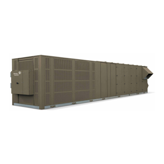
Johnson Controls 100 Series Installation Operation & Maintenance (182 pages)
PACKAGED ROOFTOP UNITS, SINGLE PACKAGED UNITS, YPAL DESIGN LEVEL G
Brand:
Johnson Controls
| Category:
Air Conditioner
| Size: 7 MB
Table of Contents
Safety Symbols
2
Changeability of this Document
3
Base Model Number
4
Table of Contents
5
FIGURE 1 - Packaged Rooftop Air Conditioning Unit
13
Coils
14
Compressor Circuiting
14
Compressor Sound Blankets
14
Condenser Coil Protection
14
Condenser Fan Motors
14
Heating Section
14
Gas Heat Design and Control Options
14
Staged Gas Heat
14
Low Ambient Operation
14
Replaceable Core Filter Driers
14
Controls
15
Section 1 - Introduction
13
Condensing Section
13
Scroll Compressors
13
Multiple Compressor Staging
13
Ecological and Economical Design
13
Cooling and Heating
13
High-Efficiency Motors
13
Indoor Air Quality (IAQ)
13
Modulating Gas Heat
13
FIGURE 2 - Double Sloped SS Drain Pan
15
TABLE 1 - Voltage Limitations
17
Rigging and Handling
18
Indoor Air Quality
15
Electrical
16
Service and Installation
16
Section 2 - Installation
17
Approvals
17
Limitations
17
Locations and Clearances
17
Unit Inspection
17
FIGURE 3 - Unit Clearances
18
FIGURE 4 - Lifting Lug Locations
19
TABLE 2 - Lifting Lug Locations
19
TABLE 3 - Physical Data
20
Electrical Data
26
Electrical Service Sizing
26
Load Definitions
26
TABLE 4 - Supply, Exhaust, Return Fan Motor Data
26
TABLE 5 - Condenser Fan Motor Data
26
TABLE 6 - Miscellaneous Electrical Data
27
TABLE 7 - Compressor Data (R-410A)
27
TABLE 8 - Electric Heat Amp Draw
27
FIGURE 5 - Drain Trap Showing Water Location During Draw through Operation Stages
28
FIGURE 6 - Trap Detail for Draw through Application
28
FIGURE 7 - Field Control Wiring - Inputs
31
FIGURE 8 - Field Control Wiring - Outputs
32
Electrical Service Sizing
33
TABLE 9 - Airflow and Entering Air/Ambient Limitations
27
Filters
28
Air Hoods for Exhaust Air
29
Air Hoods for Fixed Outside Air (Units Without Economizer)
29
Field Wiring
29
CO 2 Sensor
29
Occupied/Unoccupied Input
29
Shutdown Input
29
Smoke Purge Input
29
Space Sensor
29
Thermostat
29
VAV Heat Relay Output
30
Alarm Contacts
30
Bacnet Communication
30
Dirty Filter Switch
30
Return Air Bypass Damper
30
FIGURE 10 - Single-Point Power Supply Wiring with Non-Fused Disconnect
35
FIGURE 9 - Single-Point Power Supply Wiring
35
FIGURE 11 - Dual-Point Power Supply Wiring
36
FIGURE 12 - Static Pressure Probe Location
38
Sound and Vibration Transmission
38
FIGURE 13 - Typical Gas Piping Connection
39
Gas Connection
39
Gas Heating
39
Gas Piping
39
Gas Piping Recommendations
39
TABLE 10 - Pipe Sizes
39
Combustion Vent
40
Roof Curb Installation
37
General Information
37
Transducer Pneumatic Tubing
37
Building Pressure Transducer
37
Duct Static Transducer
37
Static Pressure Control Plastic Tubing (Pneumatic Tubing)
37
Static Pressure Probe Installation
37
Duct System
38
Duct Connection Guidelines
38
Air Hoods for Economizer
28
Condensate Drain
28
Condensate Drain Piping
28
Condensate Drain Trap
28
FIGURE 14 - Combustion Vent
40
Section 3 - Start-Up
41
Checking the System Prior to Initial Start (no Power)
41
Unit Checks
41
Crankcase Heaters
41
FIGURE 15 - Fan Isolator Spring Bolts (Total of 8)
42
Unit Checks - Power Applied
43
Compressor Oil Level Check
43
Verifying Compressor Rotation
43
TABLE 11 - R-410A Pressure Temperature Chart
45
Gas Heat Models
46
Leak Checking
46
Pre-Start Checks
47
Post Start Checks
48
Initial Start-Up
43
Refrigerant Charge
44
Checking Superheat and Subcooling
44
Subcooling (R-410A)
44
Superheat (R-410A)
44
TABLE 13 - Low Fire / High Fire - Modulating
48
TABLE 12 - Low Fire / High Fire - Staged
48
FIGURE 16 - Manifold Gas Pressure Adjustment
49
Manifold Pressure - Modulating Gas
49
Manifold Gas Pressure Adjustment
49
TABLE 14 - Low Fire (Inducer Fan on Low, 1.4" W.C. Input to Maxitrol Valve)
49
TABLE 15 - High Fire (Inducer Fan on High, 3.5" W.C. Input to Maxitrol Valve)
49
TABLE 16 - Gas Heat Performance Data
50
TABLE 17 - Fan Bearing - Lubrication Intervals
51
Condenser Coils
52
Periodic Maintenance - Three to Six Months
52
Motor Bearing Lubrication
52
Belt Tension
52
Periodic Maintenance - Yearly
52
Entire Unit Inspection
52
Sheave Alignment
52
Section 4 - Maintenance
51
General
51
Periodic Maintenance - Monthly
51
Filters
51
Linkages
51
Compressors
51
Fan Bearing Lubrication
51
FIGURE 17 - Sheave Alignment
52
Recommended Lubricant for Fan Bearings
52
Belt Replacement
53
Belts
53
FIGURE 19 - Belt Tensioning Gauge
53
FIGURE 20 - Forward Curved Fan Shaft/Wheel Marking
54
FIGURE 21 - Bearing with Setscrew Type Locking Device
55
Mounting Details
55
Eccentric Type
56
Forward Curved Fans
54
Bearing Lock Devices
55
Fan Shaft Bearings
55
FIGURE 18 - Fan Data Plate - Belt Tension
53
Filter Drier Replacement
53
Fan Motor
54
FIGURE 23 - Eccentric Cam Locking Collar Bearing Installation
56
FIGURE 22 - Bearing with Eccentric Cam
56
TABLE 18 - Set Screw Torque
57
FIGURE 24 - Split Bearing
57
Torquing of Set-Screws
57
Section 5 - Sequence of Operation
59
FIGURE 25 - Unit Options
59
TABLE 19 - Overall Status Messages
60
TABLE 20 - Current Operating Mode
62
Supply Fan
63
TABLE 21 - SZVAV Supply Fan Speed
63
Cooling and Heating Operation
64
TABLE 22 - SZVAV - Current Unit Modes
65
Variable Air Volume (VAV)
66
VAV Setup
66
Current Operating Mode
61
Night Set-Back
61
Night Set-Back Sequence of Operation
61
Night Set-Back Setup
61
Occupancy/Unoccupancy Determination
61
Single Zone VAV (SZVAV)
62
SZVAV Setup
62
Unit Type
59
Variable Air Volume (VAV)
59
Single Zone VAV (SZVAV)
59
Flexsys
60
Unit Overall Status
60
Phase Monitor
60
FIGURE 26 - Single Zone VAV (SZVAV) and Constant Volume (CV) - Occupied and Unoccupied
66
TABLE 23 - SZVAV - Supply Air Temperature (SAT) Setpoints
66
TABLE 24 - VAV Supply Fan Speed
67
FIGURE 27 - Active Duct Static Pressure Setpoint Vs. Duct Static Pressure Reset Voltage
68
Active Supply Air Temperature (SAT) Setpoint
69
Cooling and Heating Operation
69
Supply Fan
67
TABLE 26 - VAV Unit Mode
69
FIGURE 28 - Active SAT Setpoint Versus SAT Reset Voltage
70
FIGURE 29 - Active SAT Setpoint Versus RAT
71
FIGURE 31 - Active SAT Setpoint Versus Supply Fan Speed
72
FIGURE 32 - Variable Air Volume (VAV) - Occupied
72
FIGURE 33 - VAV - Unoccupied
73
TABLE 27 - Compressor Staging
74
Compressor Safety Circuits
75
Compressor Status
75
Compressor Operation
74
Fast Compressor Start
74
TABLE 28 - Compressor Model (Hp/Tonnage)
75
TABLE 29 - Compressor Status Menu
75
FIGURE 34 - Compressor Safety Chain - Without Compressor Protection Module
76
FIGURE 35 - Compressor Safety Chain - with Compressor Protection Module
77
FIGURE 36 - Compressor System Status Input to I/O Board
77
FIGURE 37 - Low Pressure Cutout (LPCO) Switch Wiring
77
Low Ambient Inhibit
79
Low Ambient Operation
79
FIGURE 38 - HGRH 3-Way Stepper Valve
80
TABLE 30 - HGRH Control Board Green LED Flash Descriptions
80
FIGURE 39 - HGRH Control Board
81
TABLE 31 - Input Signal (Jumper Location)
81
TABLE 32 - Number of Steps
81
TABLE 33 - Valve Type
81
FIGURE 40 - HGRH Piping Layout
82
HGRH Setup
82
HGRH Status
82
FIGURE 41 - Evaporator Air Temperature Active Setpoint VS Return Air Humidity
83
FIGURE 42 - HGRH SAT Active Setpoint Vs Return Air Temperature
83
HGRH Sequence of Operation
83
Condenser Fan Control
84
FIGURE 43 - Condenser Fan Contactors - Fans 1A and 1B Only for Compressor System #1
84
HGRH Faults
84
Economizer
85
Economizer Operation
85
Economizer Setup
85
FIGURE 44 - Condenser Fan VFD Wiring - Condenser Fan 1A Shown
85
Low Ambient Kit
85
Heating
86
Heating Setpoints
86
Staged Natural/Propane Gas Heat
86
TABLE 34 - Staged Gas Heat Furnace Status
87
Modulating Natural/Propane Gas Heat
88
Resetting a Compressor System Safety Lockout
78
Suction Temperature Monitoring
78
High Discharge Pressure Unloading
79
Hot Gas Reheat (HGRH)
79
HGRH System
79
TABLE 25 - Supply Fan Sync Control
69
FIGURE 30 - Active SAT Setpoint Versus OAT
71
Compressors: Control and Operation
73
Compressor Control
73
Compressor Staging
73
Compressor Systems
73
FIGURE 45 - Digital Multiplexor Connections for Staged Gas Heat
87
TABLE 35 - Modulating Gas Furnace Status
88
FIGURE 46 - Modulating Gas Furnace Sections
89
FIGURE 47 - Digital Multiplexor Connections for Modulating Gas Heat
90
FIGURE 48 - Modulating Gas Heat Staging Sequence
91
FIGURE 50 - Standard Damper with Fixed Minimum
100
FIGURE 51 - Standard Damper with Demand Ventilation
100
FIGURE 52 - Tek-Air Full IAQ with Demand Ventilation
101
TABLE 38 - Tek-Air Factory Settings
101
FIGURE 53 - Exhaust Fan Assembly
102
Exhaust Fan Assembly
103
FIGURE 54 - Return Fan Assembly
103
FIGURE 55 - Active Return Plenum Pressure Setpoint Versus Exhaust Output
105
Return Fan Assembly
105
Basic Flexsys System Design
106
Factory Recommended Setpoints
106
Flexsys
106
TABLE 39 - Recommended Setpoints
106
Current Operating Mode
107
FIGURE 56 - Flexsys - Occupied
107
Flexsys Setup
107
Cooling
108
Fan Operation
108
FIGURE 57 - Flexsys - Unoccupied
108
Heating
110
TABLE 40 - Return Air Bypass Damper
110
Underfloor Temperature Control
110
FIGURE 58 - CTB1 Field Control Wiring Inputs
111
Smoke Purge
112
Smoke Purge Sequence of Operation
112
Smoke Purge Setup
112
FIGURE 59 - User Interface Control Panel
113
Menu Select Keys
114
Navigation Keys
114
Comfort Ventilation
102
Continuous Ventilation
102
Exhaust/Return Fan
102
FIGURE 49 - Digital Multiplexor Control Board
92
TABLE 37 - Modulating Gas Heat 0-5 VDC Outputs to IPU
93
TABLE 36 - Staged Gas Heat 0-5 VDC Outputs to IPU
93
Electric Heat
94
Hot Water/Steam Heat
95
Heating Sequences
96
Supply Air Tempering
98
Ventilation
99
Ventilation Types (Damper Hardware)
99
Control Options
99
Ventilation Setup
99
1. 2 Position Damper
99
Standard Damper
99
Tek-Air Full IAQ
100
Section 6 - User Interface Control Center
113
User Interface Control Center
113
Data Entry Keys
113
TABLE 41 - Status
115
TABLE 42 - Unit Data
116
TABLE 43 - Cooling
117
TABLE 44 - Compressor Systems (1, 2, or 3)
119
TABLE 45 - Supply System
120
TABLE 46 - Heating
121
TABLE 47 - Economizer
124
TABLE 48 - Ventilation
125
TABLE 49 - Exhaust
126
TABLE 50 - Operating Hours / Start Counter
129
TABLE 51 - Service
132
History
140
TABLE 52 - Warning/Fault Order
140
Password
141
Power up Banner
141
Bacnet Wiring
142
Communication
142
Communication Ports
142
Connecting BAS to a Rooftop Unit with the IPU Board
142
FIGURE 60 - IPU Control Board
142
Additional Settings
143
Device Object Instance (DE)
143
Printer
130
Report Section
130
Setup
130
Service
131
Date / Time
127
Options
127
Program
127
Setpoints
127
Schedule
128
Operating Hours / Start Counter
129
FIGURE 61 - Mac Address Switches
143
TABLE 53 - Bacnet MS/TP, Modbus, Bacnet IP
144
Section 7 - Parameter Descriptions and Options
157
TABLE 54 - Definitions
157
Section 8 - Service
165
Analog Input Operation
165
Temperature Sensors
165
Duct Pressure Transducer
165
TABLE 55 - Temperature Sensor Resistance
165
Building Pressure Transducer
166
Return Fan Pressure Transducer
166
TABLE 58 - Return Fan Pressure Transducer Output
166
TABLE 57 - Building Pressure Transducer Output
166
TABLE 56 - Duct Pressure Transducer
166
CO 2 Sensor
167
Discharge Pressure Transducer
167
Furnace Status Input
167
Humidity Sensors
167
Suction Pressure Transducer
167
TABLE 60 - Humidity Sensor Outputs
167
TABLE 59 - Pressure Transducers
167
TABLE 62 - Furnace Status Input Modulating Gas Heat
168
TABLE 61 - CO Sensor Output
168
Faults
169
TABLE 63 - Furnace Status Input Staged Gas Heat
169
FIGURE 62 - I/O Control Board
171
FIGURE 63 - I/O Control Board - Binary Outputs
172
FIGURE 64 - I/O Control Board - Binary Inputs
173
FIGURE 66 - I/O Control Board - Analog Inputs
173
TABLE 64 - I/O Control Board - Analog Input Pinouts
174
TABLE 65 - Warning Description Table
175
TABLE 68 - Data Log Error State
180
TABLE 69 - Data Log Error Log Detail
180
TABLE 70 - si Metric Conversion
181
Temperature
181
FIGURE 65 - I/O Control Board - Analog Outputs
173
TABLE 66 - Fault Auto - Reset
177
TABLE 67 - Faults Lockout
178
Multi Media Card
179
Advertisement
Johnson Controls 100 Series Installation Operation & Maintenance (166 pages)
SINGLE PACKAGED UNIT SYPAL DESIGN LEVEL F WITH SIMPLICITY ELITE CONTROL
Brand:
Johnson Controls
| Category:
Air Conditioner
| Size: 6 MB
Table of Contents
Table of Contents
6
FIGURE 1 - Packaged Rooftop Air Conditioning Unit
13
TABLE 1 - Voltage Limitations
17
Section 2 - Installation
17
Approvals
17
Limitations
17
Locations and Clearances
17
General
17
Unit Inspection
17
FIGURE 2 - Unit Clearances
18
Location
18
Rigging and Handling
19
TABLE 2 - Lifting Lug Locations
19
TABLE 3 - Unit Weights - 050-061 Models
20
FIGURE 3 - Lifting Lug Locations
20
Unit Weights
20
TABLE 4 - Unit Center of Gravity and Corner Loads
22
TABLE 5 - Unit Corner Weights - 050-061 Models
24
Roof Curb Installation
25
Unit Placement
25
Physical Data
26
TABLE 6 - Physical Data - 050-061 Models
26
TABLE 7 - Physical Data - Compressors
27
TABLE 8 - Compressor Data - R-410A
35
TABLE 10 - Supply and Exhaust Fan Motor Data - ODP
36
TABLE 11 - Supply and Exhaust Fan Motor Data - TEFC
36
TABLE 13 - Condenser Fan Motor Rla - Low Sound Fan (Future Option)
36
TABLE 14 - Miscellaneous Electrical Data
36
TABLE 15 - Electric Heat
37
TABLE 16 - Airflow and Entering Air/Ambient Limitations
37
Air Hoods for Economizer
38
Air Hoods for Exhaust Air
38
Air Hoods for Fixed Outside Air (Units Without Economizer)
38
Condensate Drain
38
Condensate Drain Piping
38
Condensate Drain Trap
38
Field Wiring
38
FIGURE 12 - Trap Detail for Draw through Application
38
Thermostat
38
CO Sensor
39
Fan Input
39
Occupied / Unoccupied Input
39
Shutdown Input
39
Smoke Purge Input
39
Space Sensor
39
BAS Economizer Input
40
Communication
40
Dirty Filter Switch
40
Fault Output
40
Power Wiring
40
Supply Air Temperature Reset
40
VAV Heat Relay Output
40
FIGURE 13 - Wiring Connections
41
Electrical Service Sizing
42
FIGURE 14 - Single-Point Power Supply Wiring
43
FIGURE 15 - Single-Point Power Supply Wiring with Non-Fused Disconnect
44
FIGURE 16 - Dual-Point Power Supply Wiring
45
Building Pressure Transducer
46
Controls
46
Duct Static Transducer
46
Static Pressure Control Plastic Tubing
46
Static Pressure Probe Installation
46
TABLE 17 - Three Phase Power Supply Conductor Size Range
46
Transducer Pneumatic Tubing
46
FIGURE 17 - Atmospheric Sensor Probe
47
Duct Connection Guidelines
48
Duct System
48
FIGURE 18 - Discharge and Return Air Openings
48
Sound and Vibration Transmission
48
TABLE 18 - Supply Air Duct Connection Configurations
48
TABLE 19 - Return Air Duct Connection Configurations
48
FIGURE 19 - Typical Gas Piping Connection
49
Gas Connection
49
Gas Heating
49
Gas Piping
49
Gas Piping Recommendations
49
Combustion Vent
50
TABLE 9 - Power Supply Voltage Limits
35
TABLE 12 - Condenser Fan Motor Rla - Standard Fan
36
FIGURE 11 - Drain Trap Showing Water Location During Draw through Operation Stages
37
Filters
37
FIGURE 4 - Location and Dimension Drawing / 050-061 Models, Bottom Supply / Bottom Return
28
FIGURE 5 - Location and Dimension Drawing / 050-061 Models, Bottom Supply / Side Return
29
FIGURE 6 - Location and Dimension Drawing / 050-061 Models, Side Supply / Rear Return
30
FIGURE 7 - Location and Dimension Drawing, / 050-061 Models, Bottom Supply / Bottom Return
31
FIGURE 8 - Location and Dimension Drawing / 050-061 Models, Bottom Supply / Side Return
32
FIGURE 9 - Location and Dimension Drawing / 050-061 Models, Side Supply / Rear Return, Extended Cabinet
33
FIGURE 10 - Curb Layout Drawing / 050-061 Models, Standard and Extended Cabinet
34
Electrical Data
35
Electrical Service Sizing
35
Load Definitions
35
TABLE 20 - Pipe Sizes
49
FIGURE 20 - Combustion Vent
50
Section 3 - Start-Up
51
Checking the System Prior to Initial Start (no Power)
51
Unit Checks
51
Crankcase Heaters
51
FIGURE 21 - Fan Hold down Brackets
52
TABLE 21 - Condenser Coil Pressure Drop
53
TABLE 22 - R410-A Pressure / Temperature Chart
55
Gas Heat Models
56
Manifold Pressure - Staged Gas Heat
56
TABLE 23 - Low Fire / High Fire Pressures
56
Manifold Gas Pressure Adjustment
57
Leak Checking
54
Superheat (R-410A)
54
Unit Checks - Power Applied
52
Compressor Oil Level Check
53
Initial Start-Up
53
Refrigerant Charge
53
Checking Superheat and Subcooling
53
Subcooling (R-410A)
53
Verifying Compressor Rotation
53
FIGURE 22 - Manifold Gas Pressure Adjustment
57
TABLE 24 - Gas Heat Performance Data
57
Section 4 - Maintenance
59
General
59
Periodic Maintenance - Monthly
59
Compressors
59
Condenser Coils
59
Fan Bearing Lubrication
59
Filters
59
Linkages
59
Recommended Lubricant for Fan Bearings
59
TABLE 25 - Fan Bearing - Lubrication Intervals
59
FIGURE 23 - Sheave Alignment
60
Belt Replacement
61
Belt Tensioning
61
Periodic Maintenance - Three to Six Months
60
Belt Tension
60
Periodic Maintenance - Yearly
60
Entire Unit Inspection
60
Sheave Alignment
60
Belts
60
FIGURE 26 - Example of FC Fan Shaft/Wheel Marking
61
FIGURE 25 - Belt Tensioning Gauge
61
FIGURE 24 - Fan Data Plate - Belt Tension
61
Filter Drier Replacement
61
Fan Motor
62
Fan Shaft Bearings
62
Forward Curved Fans
62
Bearing Lock Devices
63
Eccentric Type
63
FIGURE 28 - Bearing with Eccentric Cam
63
FIGURE 27 - Bearing with Setscrew Type Locking Device
63
FIGURE 29 - Eccentric Cam Locking Collar Bearing Installation
64
TABLE 26 - Set Screw Torque
64
FIGURE 30 - Split Bearing
65
Torquing of Set-Screws
65
Section 5 - Sequence of Operation
67
Constant Volume Mode (CV)
67
Thermostat Input
68
Space Sensor - Hard Wired or Communicated
69
Stand Alone
70
Occupied / Unoccupied Mode
67
Unit Type
67
Variable Air Volume (VAV)
71
Cooling - Occupied with Thermostat
71
Cooling - Unoccupied with Thermostat
72
Occupied or Unoccupied Heating with a Thermostat
72
Occupied Cooling with Hard Wired or Communicated Space Sensor
72
Cooling - Unoccupied with a Hard Wired or Communicated Space Sensor
73
Heating - Occupied with a Hard Wired or Communicated Space Sensor
73
Heating - Unoccupied with a Hard Wired or Communicated Space Sensor
74
Occupied Cooling - Stand Alone
74
Cooling - Unoccupied Stand Alone
75
Heating - Occupied Stand Alone
75
Heating - Unoccupied Stand Alone
75
Compressor Staging
75
Condenser Fan Operation
75
Cooling Compressor Lockout
76
Sequence of Operation
76
Low Ambient Operation
76
Configuration (Jumpers and Potentiometers)
76
Operation and Pressure Control Range
76
TABLE 28 - VFD Jumpers
76
TABLE 29 - Potentiometer Settings
76
FIGURE 31 - Condenser Fan VFD Potentiometer Settings
77
Variable Air Volume (VAV)
78
VAV Supply Fan Speed Control
78
Economizer
79
Dry Bulb
79
Single Enthalpy
79
Dual Enthalpy
80
BAS Economizer Operation
80
Constant Volume Economizer Setpoint
80
Sequence of Operation
80
Economizer / Compressor Operation
81
Variable Air Volume Economizer Setpoint
81
Economizer PI Loop (Proportional and Integral)
82
Economizer Loading
82
Constant Volume
82
Variable Air Volume
82
Comfort Ventilation
83
TABLE 30 - Operation During off Cycle
83
TABLE 31 - Compressor on When Space Input Satisfied
83
TABLE 32 - Heat Stage on When Space Input Satisfied
84
Heating
85
Sequence of Operation
86
Space Sensor Fault Override Enable
86
Space Sensor with Setpoint Adjustment
86
Loadshed
87
Redline
87
Remote Control
87
Sequence of Operation
87
Dirty Filter
88
Intelli-Start
88
Metric Operation
88
Sequence of Operation
88
Morning Warm up
89
Subsequent Operation
89
Hydronic Heat
90
Sequence of Operation
90
Fixed Minimum
91
Hydronic Heat Freeze Stat
91
Manual
91
Sequence of Operation
91
Ventilation
91
Demand Ventilation
92
Exhaust Fan Operation
93
On/Off Control Based on Outdoor Damper Position
93
Sequence of Operation
93
Ventilation Low Ambient Minimum Position Reset
93
Modulating Damper with Fixed Speed Exhaust
94
On/Off Control Based on Building Pressure
94
Modulating Exhaust with a VFD
95
Pre-Occupancy Purge
95
Criteria for Operation
96
Energy Recovery Ventilator
96
Hot Gas Bypass
96
Low Voltage Protection
96
Outdoor Air Heating Lockout
96
Sequence of Operation
96
SAT Alarm for Heating
97
Sequence of Operation
97
Space Temperature Alarm
97
SAT Alarm for Cooling
98
Sequence of Operation
98
Alarm History
99
FIGURE 32 - Unit Controller Interface
101
Address / down Button
102
Alarm / Change
102
Character Display Addresses and Codes
102
Test/Up Button
102
Conditions of Operation
84
Excessive SAT (Supply Air Temperature) Control
84
Cooling
84
Sequence of Operation
84
TABLE 27 - Binary Outputs
76
Supply Fan Operation
77
Constant Volume (CV)
77
Section 6 - User Interface
101
Interface Methods
101
Program Button
101
Unit Controller Interface
101
TABLE 33 - Parameter Points List
103
TABLE 34 - Freenet USB
107
Device Names
111
Equipment Installation
111
Simplicity PC Data Screens
111
Sensor Readings
112
Economizer/Exhaust
113
Fans
114
Cooling Setup
115
Cooling Status
116
Heating Setup
117
Heating Status
118
System Options
119
Outputs/Status
120
Comfort/Demand Ventilation
121
Inputs
121
Clock
122
Weekly Schedule
123
Graphic
122
Weekly Schedule Settings
123
Holiday Schedule
124
Alarms
125
Revising Settings
126
Communication Using Simplicity PC
105
Simplicity PC Download
105
USB Adapter Drive - Simplicity Pocket PC
107
Establishing Communication
107
TABLE 35 - Simplicity Elite Data Map
130
Section 7 - Parameter Descriptions and Options
141
TABLE 36 - Definitions
141
Section 8 - Service
151
Analog Input Operation
151
Temperature Sensors
151
Duct Pressure Transducer
151
Building Pressure Transducer
152
Return Fan Pressure Transducer
152
TABLE 37 - Temperature Sensor Resistance
152
Discharge Pressure Transducer
153
Suction Pressure Transducer
153
TABLE 40 - Return Fan Pressure Transducer Output
153
TABLE 38 - Duct Pressure Transducer
153
TABLE 39 - Building Pressure Transducer Output
153
CO Sensor
154
Furnace Status Input
154
Humidity Sensors
154
TABLE 42 - Furnace Status Input Staged Gas Heat
154
TABLE 43 - Humidity Sensor Outputs
154
TABLE 41 - Pressure Transducers
154
FIGURE 33 - Connector Locations
155
TABLE 44 - Co Sensor Output
155
TABLE 45 - Wiring Data
156
TABLE 46 - Alarm Code Descriptions
159
Alarm Troubleshooting
161
Faults and Lockouts
159
Light Emitting Diode
159
Alarm Codes
159
Johnson Controls 100 Series Engineering Manual (102 pages)
SINGLE PACKAGE ROOFTOP UNITS 70–105 Tons Cooling and Heating (Gas, Electric, Water, and Steam) R-410A
Brand:
Johnson Controls
| Category:
Air Conditioner
| Size: 6 MB
Table of Contents
Nomenclature
2
Table of Contents
3
Introduction
5
Features and Benefits
6
Application Data
13
Physical Data
19
Weight Data
22
Cooling Performance Data - 70 Ton Model
25
Cooling Performance Data - 75 Ton Model
30
Cooling Performance Data - 80 Ton Model
35
Cooling Performance Data - 90 Ton Model
40
Cooling Performance Data - 105 Ton Model
45
Heating Performance Data - Gas/Electric Heat
50
Supply Fan Data
51
Component Static Pressure Drops
53
Gas Heat Pressure Drops
54
Electric Heat Pressure Drops
55
Exhaust Fan Data
56
Return Fan Data
57
Electrical Data
58
Controls
61
Power Wiring: Ypal070-105
70
Field Control Wiring
73
General Arrangement Drawing - 70-80 Ton Models
75
General Arrangement Drawing - 90-105 Ton Models
81
General Arrangement Drawing - Curb Layout
87
Hot Water/Steam Coil Connection Locations
89
Power/Control Entry Drawing - 70-105 Ton Models
90
Guide Specifications
91
Advertisement
Johnson Controls 100 Series Manual (56 pages)
PACKAGED ROOFTOP UNITS
Brand:
Johnson Controls
| Category:
Air Conditioner
| Size: 1 MB
Table of Contents
Table of Contents
5
Section 1 - Introduction
7
Section 2 - Connecting Bas to a Series 100/Ypal Unit with the Ipu Controller
9
Bacnet IP
9
Bacnet MS/TP
9
FIGURE 1 - IPU Controller Port Locations
10
FIGURE 2 - E-Link Connections and Addressing Instructions
11
End of Line Termination
12
Miscellaneous
12
Technical Support
12
Lon
11
Other Protocols
11
Section 3 - Unit Mode
13
Section 4 - Occupied/Unoccupied Operation
15
Section 5 - Commanding Thermostat Inputs from the Bas
17
Section 6 - Communicating a Zone Temperature
19
Section 7 - Single Zone Vav Operation
21
What Is Single Zone VAV
21
Modes of Operation
21
Occupied Standby
21
Occupied Cooling Low
21
Occupied Cooling High
21
Occupied Heating Low
21
Occupied Heating High
21
Other Points
22
Section 8 - Supply Air Temperature (Sat) Sp Reset
23
Sequence of Operation
23
Other Points that Can be Written to for SAT SP Reset
24
Flexsys
24
Constant Volume
24
Section 9 - Duct Static Pressure Reset (Bas)
25
Section 10 - Morning Warm-Up
27
Morning Warm-Up Sequence
27
Section 11 - Series 100: Flexsys Operation
29
Flexsys: Current Operating Mode (Occupied)
29
Flexsys: Fan Operation
29
Flexsys: Cooling
30
Occupied
30
Unoccupied
31
Flexsys: Compressor Control
31
Occupied Cooling W/O Bypass
31
Occupied Cooling W/ Bypass
31
Flexsys: Heating
31
Flexsys: Underfloor Temperature Control
31
Dew Point Reset
31
Active Slab Control
32
Flexsys: All Other Sequences
32
Flexsys: Bacnet Points
32
Section 12 - Bacnet Ms/Tp Points
33
TABLE 1 - Bacnet MS/TP Points
33
TABLE 2 - Series 100 Flexsys Bacnet MS/TP Points
49
TABLE 3 - Warning Description Table
51
Advertisement
Related Products
Johnson Controls 105
Johnson Controls 10 Series
Johnson Controls 16 Seer-CZF Series
Johnson Controls 13 Seer-TCGF
Johnson Controls 14.5 Seer-TCGF
Johnson Controls 13 SEER - GCGD
Johnson Controls 14.5 Seer-TCJD
Johnson Controls 13 Seer-YCJD
Johnson Controls 13 Seer-YCJF
Johnson Controls 14.5 Seer-YCJD
Johnson Controls Categories
Controller
Air Conditioner
Thermostat
Control Unit
Irrigation System
More Johnson Controls Manuals
Login
Sign In
OR
Sign in with Facebook
Sign in with Google
Upload manual
Upload from disk
Upload from URL