Johnson Controls 100 Series Engineering Manual
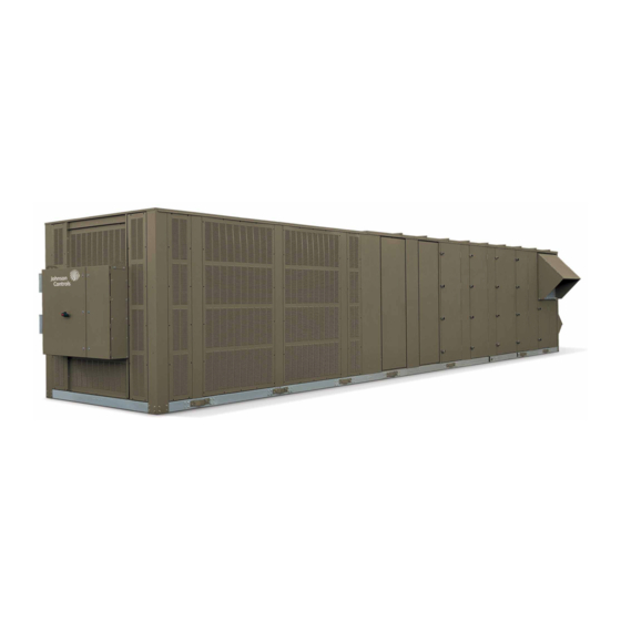
Single package rooftop units
70–105 tons
cooling and heating (gas, electric, water, and steam)
r-410a
Hide thumbs
Also See for 100 Series:
- Installation operation & maintenance (182 pages) ,
- Installation operation & maintenance (166 pages) ,
- Manual (56 pages)

Related Manuals for Johnson Controls 100 Series


Summary of Contents for Johnson Controls 100 Series
- Page 1 FORM 100.50-EG12 (918) SERIES 100 SINGLE PACKAGE ROOFTOP UNITS ENGINEERING GUIDE 70–105 Tons Cooling and Heating (Gas, Electric, Water, and Steam) R-410A Mod G LD16707...
-
Page 2: Nomenclature
V : VAV, SZVAV 0 : 380 / 3 / 60 S : Side Return F : FlexSys ™ Y : Johnson Controls A : Std. Product, Simplicity Elite B : Bottom Supply B : Special Product, Simplicity Elite L : Left Supply X : Std. -
Page 3: Table Of Contents
GENERAL ARRANGEMENT DRAWING – 70–80 TON MODELS ..............75 GENERAL ARRANGEMENT DRAWING – 90–105 TON MODELS ..............81 GENERAL ARRANGEMENT DRAWING - CURB LAYOUT ................. 87 HOT WATER/STEAM COIL CONNECTION LOCATIONS ..................89 POWER/CONTROL ENTRY DRAWING – 70-105 TON MODELS ................ 90 GUIDE SPECIFICATIONS ............................. 91 JOHNSON CONTROLS... - Page 4 FORM100.50-EG12 (918) THIS PAGE INTENTIONALLY LEFT BLANK. JOHNSON CONTROLS...
-
Page 5: Introduction
Better Economy... Lower total cost of ownership • Johnson Controls provides a standard product offering that meets the latest ASHRAE 90.1 energy efficiency requirements. • Fully modulating gas heat and greater steps of capacity control offer superior off- design performance while maintaining optimum occupant comfort. -
Page 6: Features And Benefits
80–250 kW depending on the single package unit model size. The number of stages varies by size and voltage, but all have a minimum of two stages of capacity. Units with electric heat are ETL listed. JOHNSON CONTROLS... - Page 7 0.0°F through the use of suction and discharge pressure transducers on the circuit(s). Pressure Transducers with Readout Capability – This option includes suction and dis- charge pressure transducers on each circuit and provides pressure readout of all circuits at the unit control panel. JOHNSON CONTROLS...
- Page 8 Barometric Relief – This option does not include an exhaust or return fan, but rather uses barometric relief dampers to exhaust air from the building. The dampers will open relative to the building pressure. The opening pressure is adjustable via a spring tension adjustment. JOHNSON CONTROLS...
- Page 9 The supply fan can be optionally equipped with a piezo ring to precisely measure the amount of air delivered to the conditioned space. The speed of the supply fan is controlled by a VFD. JOHNSON CONTROLS...
- Page 10 CONDENSER FEATURES AND OPTIONS Scroll Compressors – Reliable, efficient, trouble-free operation is the true measure of a single package unit’s value. That’s why Johnson Controls Series 100 Single package units use established scroll compressor technology to deliver dependable, economical performance in a wide range of applications. With the Series 100 Single package units, you get the latest generation of compressor enhancements added to the scroll’s inherent...
- Page 11 Magnahelic Filter Pressure Gauge – On units equipped with downstream filtration, a magnahelic filter gauge is included and visible on the exterior of the unit. The filter gauge measures the air pressure drop for through the rigid filter bank to indicate when replace- ment is required. JOHNSON CONTROLS...
- Page 12 FORM100.50-EG12 (918) Features and Benefits (Cont'd) YPAL070–105 MODEL JOHNSON CONTROLS...
-
Page 13: Application Data
Unit clearances are designed so that technicians have enough space between units, building walls, and edges of building to gain access safely. In cases where space is limited, please call your local Johnson Controls representative for addi- tional information. - Page 14 Erecting a fence around the unit is common practice. • Roof curb – Johnson Controls offers optional roof curbs designed specifically for the Series 100 footprint. These curbs come in full perimeter or open condenser models and are shipped disassembled and require field assembly and installation.
- Page 15 HVAC equipment. If the application calls for horizontal supply and return air, Johnson Controls can ship it from the factory as a horizontal unit. This option eliminates the need for field modification of equipment saving time and money.
- Page 16 FIGURE 2 - TRADITIONAL OVERHEAD VAV AIR DELIVERY SYSTEM For VAV applications, the Johnson Controls Series 100 unit uses a VFD to modulate fan speed and maintain a constant duct static pressure. VFDs offer superior control over the operation of the unit at part load, and offer the additional benefits of quieter and more ef- ficient operation when compared to IGV.
- Page 17 Johnson Controls offers a powered return fan that is located in the return plenum. This fan operates coincidentally with the supply fan and draws return air back through the return ductwork and into a pressurized plenum.
- Page 18 Control is accomplished via either a discharge damper or a VFD. Johnson Controls recommends the use of a VFD to reduce energy consumption, sound levels and improved reliability due to fewer moving parts.
-
Page 19: Physical Data
Motor Size Range (min. to max. HP, total 10–30 10–30 10–30 10–40 10–40 for two fans) Airflow Range (min. to max. CFM) 4,000–32,000 4,000–32,000 4,000–32,000 4,000–36,000 4,000–36,000 Static Pressure Range (min. to max. iwg) 0–3 inches 0–3 inches 0–3 inches 0–3 inches 0–3 inches JOHNSON CONTROLS... - Page 20 FILTERS - 12-INCH RIGID 95% IN POST-FILTER POSITION (MERV 14) Quantity 2/7/9 2/7/9 2/7/9 7/12 7/12 16x20/25x16/ 16x20/25x16/ 16x20/25x16/ Size (length x width) (inch) 25x16/25x20 25x16/25x20 25x20 25x20 25x20 Total Filter Face Area (square feet) 55.1 55.1 55.1 61.1 61.1 JOHNSON CONTROLS...
- Page 21 39.6 SYS 3 - LB 42.4 36.2 45.4 REFRIGERANT CHARGE (R-410A EXTD CABINET) SYS 1 - LB 40.7 40.7 44.2 48.1 SYS 2 - LB 41.2 35.1 34.7 42.3 SYS 3 - LB 45.4 35.7 35.7 38.9 48.1 JOHNSON CONTROLS...
-
Page 22: Weight Data
2-inch throwaway filter. 2. Base weights shown represent approximate operating weights and have a ±10% accuracy. To calculate weight for a specific configura- tion, use YORKworks or contact a Johnson Controls sales representative. TABLE 6 - COMPONENT WEIGHTS (LBS) - Page 23 Rear OA Hood Tray & Liner OA Filters Back Top OA Filters Back Bottom OA Filters Right Top OA Filters Right Bottom OA Filters Left Top OA Filters Left Bottom POWER EXHAUST Exhaust Motor Base, 256 T Frame Exhaust Fan JOHNSON CONTROLS...
- Page 24 1. The weight given is the total weight of all eight aluminum coils and all eight copper coils, respectively. Indicates that particular option is not available with that model size. 2. The 0–100% AMS option needs some predetermined minimum airflow rate to work. JOHNSON CONTROLS...
-
Page 25: Cooling Performance Data - 70 Ton Model
1004 834 1004 757 1004 680 1004 603 1002 525 1001 448 1004 371 27,500 1012 860 1012 779 1012 698 1012 617 1010 535 1008 454 1012 374 29,000 * Rated performance is at sea level. Cooling capacities are gross cooling capacity. JOHNSON CONTROLS... - Page 26 375 1128 343 20,000 486 1003 438 372 1013 342 21,500 504 1036 456 23,000 509 1021 453 24,500 514 1006 450 26,000 27,500 29,000 * Rated performance is at sea level. Cooling capacities are gross cooling capacity. JOHNSON CONTROLS...
- Page 27 358 1837 324 15,500 349 1837 322 17,000 369 1594 333 18,500 389 1351 344 20,000 409 1109 355 21,500 23,000 24,500 26,000 27,500 29,000 * Rated performance is at sea level. Cooling capacities are gross cooling capacity. JOHNSON CONTROLS...
- Page 28 353 1277 312 14,000 354 1284 314 15,500 354 1291 316 17,000 369 1175 324 18,500 384 1059 332 20,000 21,500 23,000 24,500 26,000 27,500 29,000 * Rated performance is at sea level. Cooling capacities are gross cooling capacity. JOHNSON CONTROLS...
- Page 29 ENTERING AIR DRY BULB 95°F 92°F 89°F 86°F 83°F 80°F 77°F 74°F 71°F 68°F 14,000 15,500 17,000 18,500 20,000 21,500 23,000 24,500 26,000 27,500 29,000 * Rated performance is at sea level. Cooling capacities are gross cooling capacity. JOHNSON CONTROLS...
-
Page 30: Cooling Performance Data - 75 Ton Model
1067 1019 1066 933 1064 848 1063 762 1062 676 1060 591 1059 506 1058 421 1057 336 29,000 1030 1154 1020 1066 1009 978 1030 1344 1001 1249 972 1154 943 1059 931 * Rated performance is at sea level. Cooling capacities are gross cooling capacity. JOHNSON CONTROLS... - Page 31 1026 1004 1024 919 1023 833 1021 748 1020 662 1018 575 1017 490 1015 405 1014 319 29,000 998 1141 985 1051 972 998 1327 969 1231 941 1135 913 1039 898 * Rated performance is at sea level. Cooling capacities are gross cooling capacity. JOHNSON CONTROLS...
- Page 32 1044 863 1043 778 1042 693 1040 608 1038 522 1036 437 1034 350 29,000 966 1129 951 1036 935 966 1311 938 1214 910 1116 883 1019 864 * Rated performance is at sea level. Cooling capacities are gross cooling capacity. JOHNSON CONTROLS...
- Page 33 913 1068 898 913 1242 886 1149 859 1056 833 29,000 929 1112 910 1019 892 928 1295 901 1198 874 1100 847 1003 826 * Rated performance is at sea level. Cooling capacities are gross cooling capacity. JOHNSON CONTROLS...
- Page 34 860 1174 835 1086 810 27,500 876 1052 858 875 1227 849 1134 823 1041 797 29,000 891 1095 870 1003 849 890 1280 864 1182 837 1084 811 * Rated performance is at sea level. Cooling capacities are gross cooling capacity. JOHNSON CONTROLS...
-
Page 35: Cooling Performance Data - 80 Ton Model
1102 1281 1087 1179 1071 1077 874 835 1055 878 1054 781 1052 684 1051 586 1050 489 1049 392 1101 1495 1071 1384 1040 1274 847 1003 992 1058 973 * Rated performance is at sea level. Cooling capacities are gross cooling capacity. JOHNSON CONTROLS... - Page 36 1068 1268 1050 1165 1032 1062 1014 959 1013 862 1012 765 1010 668 1009 570 1008 473 1006 376 1067 1479 1037 1369 1007 1259 977 1149 957 1043 936 * Rated performance is at sea level. Cooling capacities are gross cooling capacity. JOHNSON CONTROLS...
- Page 37 1043 1096 1040 998 1037 901 1033 803 1032 706 1031 609 1030 511 1029 413 1028 315 33,000 1034 1256 1013 1151 993 1047 973 1033 1463 1004 1353 974 1244 945 1134 922 1028 898 * Rated performance is at sea level. Cooling capacities are gross cooling capacity. JOHNSON CONTROLS...
- Page 38 1046 938 1044 841 1043 743 1042 645 1041 550 1040 454 1038 354 998 1082 993 33,000 992 1241 970 1136 947 1030 925 991 1445 963 1336 935 1226 906 1117 881 1009 857 * Rated performance is at sea level. Cooling capacities are gross cooling capacity. JOHNSON CONTROLS...
- Page 39 932 1359 905 1255 878 1152 851 1048 828 953 1068 945 33,000 951 1227 926 1120 902 1012 878 950 1428 922 1318 895 1209 867 1099 841 * Rated performance is at sea level. Cooling capacities are gross cooling capacity. JOHNSON CONTROLS...
-
Page 40: Cooling Performance Data - 90 Ton Model
1276 1274 1271 1269 36,000 1253 1238 1224 1209 1207 1204 1201 1197 1194 1190 1252 1218 1184 1149 1133 1116 1112 1109 1106 1102 * Rated performance is at sea level. Cooling capacities are gross cooling capacity. JOHNSON CONTROLS... - Page 41 1228 1225 1222 1219 36,000 1215 1198 1181 1163 1161 1158 1155 1151 1147 1143 1215 1181 1147 1114 1094 1074 1070 1067 1063 1059 * Rated performance is at sea level. Cooling capacities are gross cooling capacity. JOHNSON CONTROLS...
- Page 42 1179 1176 1173 1170 36,000 1178 1158 1138 1118 1115 1113 1109 1105 1100 1096 1177 1144 1111 1078 1055 1032 1028 1024 1020 1017 * Rated performance is at sea level. Cooling capacities are gross cooling capacity. JOHNSON CONTROLS...
- Page 43 1131 104 1109 103 1086 103 1063 102 1061 102 1058 103 1053 103 1049 103 1044 103 1039 103 1131 104 1099 103 1066 102 1034 102 1009 101 * Rated performance is at sea level. Cooling capacities are gross cooling capacity. JOHNSON CONTROLS...
- Page 44 1090 113 1083 113 1076 113 1069 113 1066 113 1062 113 1058 114 1053 114 1049 114 36,000 1085 113 1060 113 1034 112 1009 112 1006 112 1003 112 1085 113 1053 113 1022 112 * Rated performance is at sea level. Cooling capacities are gross cooling capacity. JOHNSON CONTROLS...
-
Page 45: Cooling Performance Data - 105 Ton Model
1466 95 1456 95 1445 94 1435 94 1434 94 1432 94 1415 94 1397 93 1380 93 1362 93 1469 95 1427 94 1385 93 1343 92 1332 92 1322 92 1304 91 1286 91 1268 90 1250 90 * Rated performance is at sea level. Cooling capacities are gross cooling capacity. JOHNSON CONTROLS... - Page 46 1422 104 1407 104 1392 104 1377 103 1375 103 1372 103 1364 103 1355 103 1346 103 1337 102 1423 104 1382 103 1341 102 1300 101 1285 101 1269 101 1259 100 1249 100 1240 100 1230 100 * Rated performance is at sea level. Cooling capacities are gross cooling capacity. JOHNSON CONTROLS...
- Page 47 1377 114 1358 113 1339 113 1319 112 1316 112 1313 112 1312 112 1312 112 1312 112 1312 112 1376 114 1337 113 1298 112 1258 111 1237 110 1216 110 1214 109 1213 109 1212 109 1210 109 * Rated performance is at sea level. Cooling capacities are gross cooling capacity. JOHNSON CONTROLS...
- Page 48 1323 126 1300 125 1277 125 1254 124 1251 124 1249 124 1247 124 1246 124 1244 124 1243 123 1322 126 1284 125 1246 124 1207 123 1181 122 1154 121 1153 121 1151 121 1150 121 1149 121 * Rated performance is at sea level. Cooling capacities are gross cooling capacity. JOHNSON CONTROLS...
- Page 49 1269 138 1242 137 1215 136 1188 135 1186 135 1185 135 1182 135 1179 135 1176 135 1173 135 1268 138 1231 137 1194 136 1157 135 1124 134 1092 133 1091 133 1090 133 1089 133 1088 132 * Rated performance is at sea level. Cooling capacities are gross cooling capacity. JOHNSON CONTROLS...
-
Page 50: Heating Performance Data - Gas/Electric Heat
Minimum gas pressure is 4.5 iwg. ELECTRIC HEATING TABLE 13 - ELECTRIC HEAT PERFORMANCE DATA HEAT CAPACITY AIRFLOW MIN MAX TEMP RISE UNIT SIZE (KW) (MBH) (CFM) (°F) 10,000 12,000 70–80 TON 14,000 15,000 12,000 14,000 90–105 TON 15,000 16,000 JOHNSON CONTROLS... -
Page 51: Supply Fan Data
34.0 40.3 47.2 34,000 30.9 38.2 44.8 NOTE: For performance at operating points not included in these tables, consult your local Johnson Controls representative. TABLE 15 - YPAL070–105: 32-INCH AIRFOIL FAN TOTAL STATIC PRESSURE (IWG) STD. AIR 18,000 12.8 1046 17.0... - Page 52 34.3 1,261 40.6 1,313 47.1 NOTE: For performance at operating points not included in these tables, consult your local Johnson Controls representative. TABLE 17 - YPAL070–105: DDP402-9-120 DIRECT DRIVE PLENUM (DDP) SUPPLY FAN TOTAL STATIC PRESSURE (IWG) STD. AIR 18,000 12.8...
-
Page 53: Component Static Pressure Drops
1. Return air opening pressure drop does not include an exhaust fan. Use the value in the Powered Exhaust column to determine return air pressure drop attributed to the exhaust fan assembly. 2. Front return is not available with barometric relief, exhaust fans or return fans. 3. Pressure drop for rigid filter rack includes a 2-inch throwaway pre-filter. JOHNSON CONTROLS... -
Page 54: Gas Heat Pressure Drops
0.11 0.11 20,000 0.09 0.13 0.14 22,000 0.11 0.16 0.17 24,000 0.13 0.19 0.20 26,000 0.15 0.22 0.23 28,000 0.17 0.26 0.27 30,000 0.20 0.30 0.31 32,000 0.23 0.34 0.35 34,000 0.26 0.38 0.40 36,000 0.29 0.43 0.45 JOHNSON CONTROLS... -
Page 55: Electric Heat Pressure Drops
0.44 36,000 0.22 0.29 0.36 0.50 TABLE 21 - ELECTRIC HEATER SIZE AVAILABILITY BY UNIT SIZE MODEL 80kW 108kW 150kW* 200kW* 250kW* YPAL070–080 YPAL090–105** *150–250kW electric heat not available in 200-230V configurations. **For 208V YPAL105, contact Johnson Controls. JOHNSON CONTROLS... -
Page 56: Exhaust Fan Data
13.6 24000 11.7 12.7 14.0 26000 14.7 NOTE: For performance at operating points not included in these tables, consult your local Johnson Controls representative. TABLE 23 - EXHAUST FAN PERFORMANCE FAN TYPE 18X18 20X18 YPAL070–080 YPAL090–105 TABLE 24 - DUAL 20 X 18 FORWARD-CURVED FAN TOTAL STATIC PRESSURE (IWG) 0.25... -
Page 57: Return Fan Data
1864 39.8 1912 36000 29.7 1813 33.3 1859 36.9 1902 NOTE: For performance at operating points not included in these tables, consult your local Johnson Controls representative. TABLE 26 - RETURN FAN PERFORMANCE FAN TYPE 2X270 YPAL070–080 YPAL090–105 JOHNSON CONTROLS... -
Page 58: Electrical Data
14.7 ZP154 51.3 23.1 19.9 YPAL 80 TON ZP137 48.1 18.6 14.7 ZP182 55.8 26.9 23.7 YPAL 90 TON ZP154 51.3 23.1 19.9 ZP182 26.9 23.7 YPAL 105 TON ZP236 30.8 25.0 NOTE: *RLA data is per compressor JOHNSON CONTROLS... - Page 59 TABLE 32 - ELECTRIC HEAT AMP DRAW 200V/3Ph/60Hz 240V/3Ph/60Hz 480V/3Ph/60Hz 600V/3Ph/60Hz AMPS AMPS AMPS AMPS NOTE Heaters will be sized as follows: 208V heaters rated at 208V, 230V heaters rated at 240V, 460V heaters rated at 480V, 575V heaters rated at 600V. JOHNSON CONTROLS...
- Page 60 TABLE 33 - ELECTRICAL HEAT STAGES 70–80 Tons 80 KW 108 KW 150 KW 200 KW 200V/3/60Hz Available 230V/3/60Hz Voltages 460V/3/60Hz 575V/3/60Hz 90–105 tons 108 KW 150 KW 200 KW 250 KW 200V/3/60Hz 230V/3/60Hz Available Voltages 460V/3/60Hz 575V/3/60Hz JOHNSON CONTROLS...
-
Page 61: Controls
CONTROL SEQUENCES (VAV & SZVAV) GENERAL The control system for the Johnson Controls Series 100 single package unit is fully self- contained and based around a single package unit controller. To aid in unit setup, mainte- nance, and operation, the single package unit controller is equipped with a user interface that is based around a 4 line x 20 character backlit LCD display. - Page 62 OAT is less than the ref- erence temperature setting. This method of economizing allows the reference temperature setting to be set higher than the dry bulb economizer and is consequently a more efficient single package unit economizer. JOHNSON CONTROLS...
- Page 63 Because this type of exhaust is not powered, the amount of air exhausted will be limited to the static pressure that will need to be overcome. JOHNSON CONTROLS...
- Page 64 With the optional low ambient controls, mechanical cooling is allowed down to outside air tem- peratures of 0.0°F. JOHNSON CONTROLS...
- Page 65 RAT is equal to or less than the RAT heating setpoint minus 0.5°F, the unit controller will place the unit in the occupied heating mode. The unit will remain in the occupied heating mode until the RAT is equal to or greater than the RAT heating setpoint plus 0.5°F. JOHNSON CONTROLS...
- Page 66 0.5°F, the unit controller will place the unit in the unoccupied heating mode. The unit will remain in the unoccupied heating mode until the zone temperature is equal to or greater than the unoccupied zone heating setpoint plus 0.5°F. LD20073 FIGURE 4 - OPERATIONAL MODE: VARIABLE AIR VOLUME (VAV) JOHNSON CONTROLS...
- Page 67 In the hardwired mode the input is an analog input to the control. In the communicated mode the input is a serial input from a bas con- trol system. LD19888 FIGURE 5 - OPERATIONAL MODE: SINGLE ZONE VAV (SZVAV) JOHNSON CONTROLS...
- Page 68 If conditions are suitable for economizing, the single package unit controller will modulate the outside air damper in addition to staging heating steps up and down to maintain the zone temperature setpoint. JOHNSON CONTROLS...
- Page 69 4 AWG-600 kcmil 380V-60 (2-in.) 3/0-250 kcmil 4 AWG-500 kcmil 4 AWG-500 kcmil 14 AWG-2/0 460V (2-in.) 3/0-250 kcmil 4 AWG-500 kcmil 6 AWG-400 kcmil 14 AWG-2/0 575V (2-in.) 3/0-250 kcmil 6 AWG-350 kcmil 14 AWG-2/0 14 AWG-2/0 JOHNSON CONTROLS...
-
Page 70: Power Wiring: Ypal070-105
6. On units with an optional disconnect switch, the supplied disconnect switch is a “Disconnecting Means” as defined in the N.E.C. Section 100, and is intended for isolating the unit from the available power supply to perform maintenance and troubleshooting. This disconnect switch is not intended to be a Load Break Device. FIGURE 6 - SINGLE-POINT POWER SUPPLY WIRING JOHNSON CONTROLS... - Page 71 100, and is intended for isolating the unit from the available power supply to perform maintenance and troubleshooting. This disconnect switch is not intended to be a Load Break Device. FIGURE 7 - SINGLE-POINT POWER SUPPLY WIRING WITH NON-FUSED DISCONNECT JOHNSON CONTROLS...
- Page 72 6. On units with an optional disconnect switch, the supplied disconnect switch is a “Disconnecting Means” as defined in the N.E.C. Section 100, and is intended for isolating the unit from the available power supply to perform maintenance and troubleshooting. This disconnect switch is not intended to be a Load Break Device. FIGURE 8 - DUAL-POINT POWER SUPPLY WIRING JOHNSON CONTROLS...
-
Page 73: Field Control Wiring
FORM 100.50-EG12 (918) Field Control Wiring ld08184 FIGURE 9 - FIELD CONTROL WIRING JOHNSON CONTROLS... - Page 74 FORM100.50-EG12 (918) Field Control Wiring (Cont'd) FIGURE 10 - FIELD CONTROL WIRING JOHNSON CONTROLS...
-
Page 75: General Arrangement Drawing - 70-80 Ton Models
FORM 100.50-EG12 (918) General Arrangement Drawing – 70–80 Ton Models BOTTOM SUPPLY / BOTTOM RETURN FIGURE 11 - GENERAL ARRANGEMENT DRAWING LD08128 JOHNSON CONTROLS... - Page 76 FORM100.50-EG12 (918) General Arrangement Drawing – 70–80 Ton Models (Cont'd) LEFT SUPPLY / LEFT RETURN FIGURE 12 - GENERAL ARRANGEMENT DRAWING JOHNSON CONTROLS...
- Page 77 FORM 100.50-EG12 (918) LEFT SUPPLY / FRONT RETURN FIGURE 13 - GENERAL ARRANGEMENT DRAWING LD08130 JOHNSON CONTROLS...
- Page 78 FORM100.50-EG12 (918) General Arrangement Drawing – 70–80 Ton Models (Cont'd) EXTENDED CABINET / BOTTOM SUPPLY / BOTTOM RETURN FIGURE 14 - GENERAL ARRANGEMENT DRAWING JOHNSON CONTROLS...
- Page 79 FORM 100.50-EG12 (918) EXTENDED CABINET / LEFT SUPPLY / LEFT RETURN FIGURE 15 - GENERAL ARRANGEMENT DRAWING ld08137 JOHNSON CONTROLS...
- Page 80 FORM100.50-EG12 (918) General Arrangement Drawing – 70–80 Ton Models (Cont'd) EXTENDED CABINET / LEFT SUPPLY / FRONT RETURN FIGURE 16 - GENERAL ARRANGEMENT DRAWING JOHNSON CONTROLS...
-
Page 81: General Arrangement Drawing - 90-105 Ton Models
FORM 100.50-EG12 (918) General Arrangement Drawing – 90–105 Ton Models BOTTOM SUPPLY / BOTTOM RETURN FIGURE 17 - GENERAL ARRANGEMENT DRAWING ld08131 JOHNSON CONTROLS... - Page 82 FORM100.50-EG12 (918) General Arrangement Drawing – 90–105 Ton Models (Cont'd) LEFT SUPPLY / LEFT RETURN FIGURE 18 - GENERAL ARRANGEMENT DRAWING JOHNSON CONTROLS...
- Page 83 FORM 100.50-EG12 (918) LEFT SUPPLY / FRONT RETURN FIGURE 19 - GENERAL ARRANGEMENT DRAWING ld08133 JOHNSON CONTROLS...
- Page 84 FORM100.50-EG12 (918) General Arrangement Drawing – 90–105 Ton Models (Cont'd) EXTENDED CABINET / BOTTOM SUPPLY / BOTTOM RETURN FIGURE 20 - GENERAL ARRANGEMENT DRAWING JOHNSON CONTROLS...
- Page 85 FORM 100.50-EG12 (918) EXTENDED CABINET / LEFT SUPPLY / LEFT RETURN FIGURE 21 - GENERAL ARRANGEMENT DRAWING LD08137 JOHNSON CONTROLS...
- Page 86 FORM100.50-EG12 (918) General Arrangement Drawing – 90–105 Ton Models (Cont'd) EXTENDED CABINET / LEFT SUPPLY / BOTTOM RETURN FIGURE 22 - GENERAL ARRANGEMENT DRAWING JOHNSON CONTROLS...
-
Page 87: General Arrangement Drawing - Curb Layout
The cap design must be sloped away from the supply duct opening to the end of the unit for the drainage of the moisture off of the top of the cap. FIGURE 23 - GENERAL ARRANGEMENT DRAWING JOHNSON CONTROLS... - Page 88 2. Curb configuration for “bottom” return and “bottom” supply. 3. These drawings are not intended as construction documents for the field fabricated roof curbs. Johnson Controls will not be responsible for the unit fit up, leak integrity, or sound level for installation using field fabricated roof curbs.
-
Page 89: Hot Water/Steam Coil Connection Locations
FPT = Female Pipe Thread Hot Water Coil Connections w/ controls are valve connections facing bottom of the unit, at locations indicated. Steam and Hot Water connections w/o controls are fittings connections facing side of the unit, at locations indicated. JOHNSON CONTROLS... -
Page 90: Power/Control Entry Drawing - 70-105 Ton Models
FORM100.50-EG12 (918) Power/Control Entry Drawing – 70-105 Ton Models LD19503 FIGURE 25 - POWER/CONTROL ENTRY DRAWING – 70 - 105 TON MODELS JOHNSON CONTROLS... -
Page 91: Guide Specifications
1. Structural supports for units. 2. Roof curb transition. 3. Piping size and connection/header locations. 4. Electrical power requirements and wire/conduit and overcurrent protection sizes. 5. All costs incurred to modify the building provisions to accept the furnished units. JOHNSON CONTROLS... - Page 92 460V [208V/230V/575V] three-phase, 60Hz power supply, outdoor air handling section with return and supply openings, discharge plenum, direct-expansion refrigerant condensing section. JOHNSON CONTROLS...
- Page 93 0–25% outside air shall be provided. The minimum position shall be manually adjustable from 0–25%. Control shall be based on the occupied mode of the unit. For occupied mode, the damper shall be open to the minimum position and for unoccupied, it shall be closed. JOHNSON CONTROLS...
- Page 94 A discharge damper shall be provided to modulate building exhaust. The damper shall be controlled via building pressure. The return damper shall linked with the outside air damper to modulate volumes of return and outside airflows. JOHNSON CONTROLS...
- Page 95 3/8-inch OD copper, with internally enhanced tubes. Fins shall be enhanced me- chanically expanded to bond with the copper tubes. Coil casing shall be fabricated from heavy gauge galvanized steel. All coils shall be pressure tested at a minimum of 450 psig. JOHNSON CONTROLS...
- Page 96 Airflow measurement device shall be ca¬pable of measurement accuracy of +/-5%. Airflow measurement ring and trans¬ducer shall be supplied for integration into a field-supplied controller. f. Fan Inlet Screen: Unit shall be provided with a fan inlet screen. JOHNSON CONTROLS...
- Page 97 3. Modulating Gas Heat: The heating section shall include an induced draft furnace in 8:1 modulation [16:1, 24:1] of heating capacity. Heat Exchanger(s): The heat exchanger(s) shall be constructed of tubular alumi- nized steel [stainless steel], with stainless steel flue baffles and flue assembly. JOHNSON CONTROLS...
- Page 98 Freezestat shall be provided to prevent coil freeze-up. Testing: Completed coil, including headers, connections and return bends shall be tested with 325 pounds compressed air under water. Coils shall be designed for op- eration at 250 psig design working pressure. JOHNSON CONTROLS...
- Page 99 All compressor-to-pipe connections shall be brazed to minimize potential for leaks. Each compressor shall include a replaceable suction screen, discharge line check valve, and oil sight glass. JOHNSON CONTROLS...
- Page 100 In the event of a unit shutdown or alarm, the oper- ating conditions, date and time shall be stored in the shutdown history to facilitate service and troubleshooting. JOHNSON CONTROLS...
- Page 101 Manufacturer instructions. Adjust and level the single package unit on support structure. INSPECTION AND START-UP SUPERVISION A factory-trained service representative of the manufacturer shall supervise the unit start- up and application specific calibration of control components. JOHNSON CONTROLS...
- Page 102 Printed on recycled paper Form 100.50-EG12 (918) NEW RELEASE © 2018 Johnson Controls 100 JCI Way, York, Pennsylvania USA 17406-8469 Printed in USA www.johnsoncontrols.com Issued on 9/17/2018...
Need help?
Do you have a question about the 100 Series and is the answer not in the manual?
Questions and answers